
Related Manuals for Toro 07413LT


Summary of Contents for Toro 07413LT
- Page 1 Form No. 3461-460 Rev A Workman ® GTX Lithium Utility Vehicle Model No. 07413LT—Serial No. 414318861 and Up Model No. 07413TC—Serial No. 414400000 and Up *3461-460* Register at www.Toro.com. Original Instructions (EN)
- Page 2 • Warning indicates a potentially hazardous Whenever you need service, genuine Toro parts, or situation which, if not avoided, could result in additional information, contact an Authorized Service death or serious injury.
-
Page 3: Table Of Contents
Contents Disconnecting the Batteries ......37 Connecting the Batteries ........37 Replacing a Fuse..........38 Safety ............... 4 Maintaining the Headlights ....... 39 General Safety ........... 4 Servicing the Batteries........40 Safety and Instructional Decals ......5 Maintaining the Battery Charger ....... 40 Setup ................ -
Page 4: Safety
Safety This machine has been designed in accordance with the requirements of SAE J2258 (Nov 2016). General Safety This product is capable of causing personal injury. Always follow all safety instructions to avoid serious personal injury. • Read and understand the contents of this Operator’s Manual before you start the machine. -
Page 5: Safety And Instructional Decals
Safety and Instructional Decals Safety decals and instructions are easily visible to the operator and are located near any area of potential danger. Replace any decal that is damaged or missing. decal115-7739 115-7739 1. Falling, crushing hazard—do not carry passengers. decal131-8527 131-8527 1. - Page 6 decal145-2275 145-2275 1. 12 V plug 6. Electric relay (20 A) 2. Read the Operator’s 7. Horn (20 A) Manual for fuse information. 3. Display (2 A); fuse located 8. USB power point (5 A) under the hood. decal139-4610 4. Power (10 A) 9.
-
Page 7: Setup
Setup Loose Parts Use the chart below to verify that all parts have been shipped. Procedure Description Qty. Steering wheel Locknut Install the steering wheel (international models only). Wheel cover Screw – No parts required Check the fluid levels and tire pressure. –... -
Page 8: Checking The Fluid Levels And Tire Pressure
Use 3 screws to secure the wheel cover to the steering wheel. Torque the 3 screws to 0.6 N∙m (5 in-lb). Burnishing the Brakes No Parts Required Procedure To ensure optimum performance of the brake system, burnish (break-in) the brakes before use. Bring the machine up to full speed, apply the brakes to rapidly stop the machine without locking up the tires. -
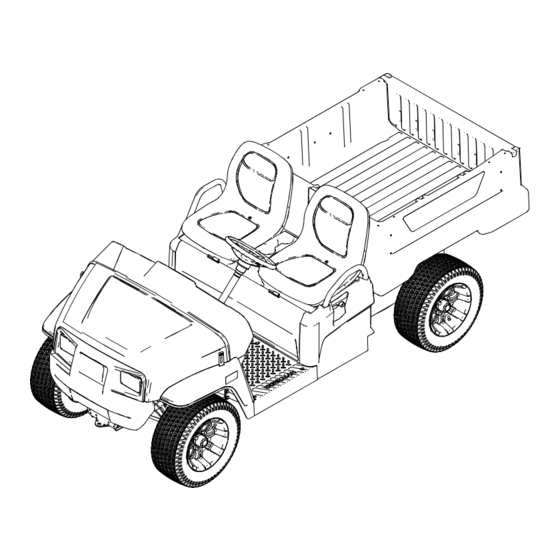
Page 9: Product Overview
Product Overview g319171 Figure 5 1. Hood latch 3. Cargo bed 5. Battery charger 2. Steering wheel 4. Towing tongue 6. Cargo-bed lever g319172 Figure 6 1. Passenger handhold 3. Trailer hitch 2. Parking-brake lever 4. Rear cargo-bed-accessory mount... -
Page 10: Controls
Controls Control Panel g377919 Figure 7 1. Horn switch 6. Parking-brake lever 2. Light switch 7. USB power point 3. Display 8. Accelerator pedal 4. Gear-shift selector 9. Brake pedal 5. Key switch Accelerator Pedal Brake Pedal Use the accelerator pedal (Figure 7) to vary ground Use the brake pedal to stop or slow the machine... - Page 11 Parking-Brake Lever Direction Selector The parking-brake lever is located on the control The direction selector is located to the left of the panel (Figure parking-brake lever. The direction selector has 3 positions: F , and N (Figure ORWARD EVERSE EUTRAL Whenever you shut off the machine, engage the parking brake to prevent the machine from accidentally Note:...
-
Page 12: Display
Display The display shows information about your machine, such as the operating status, various diagnostics, and other information about the machine (Figure 10). g321175 Figure 11 1. Startup screen 3. Software revision 2. Battery voltage g320256 Figure 10 1. Indicator light 2. - Page 13 The run screen with the current machine speed (Figure 15) appears when you are driving the machine. g321177 g321181 Figure 13 Figure 15 1. Charging screen 3. Battery currently charging 1. Current machine speed indicator 2. Battery life 4. Estimated time to fully charge the machine An active fault code (Figure...
- Page 14 Supervisor Speed-Limit Switch Icon Descriptions The supervisor speed-limit switch, located under Direction—F position ORWARD the seat assembly, has 2 positions: P ERFORMANCE and E . Rotate the switch clockwise to the CONOMY position to limit the maximum machine CONOMY Direction—N position EUTRAL speed to 19 km/h (12 mph).
-
Page 15: Specifications
28 cm (11 inches) inside Attachments/Accessories A selection of Toro approved attachments and accessories is available for use with the machine to enhance and expand its capabilities. Contact your Authorized Service Dealer or authorized Toro distributor or go to www.Toro.com for a list of all approved attachments and accessories. -
Page 16: Before Operation
Operation section (if applicable) in the Important: Do not exceed the maximum air Installation Instructions. Visit www.Toro.com for your pressure indicated on the sidewall of the tire. instructions or scan the QR code (if applicable) on your attachment. -
Page 17: Breaking In A New Machine
Breaking in a New Machine During Operation Service Interval: After the first 100 hours—Perform During Operation Safety the breaking in a new machine guidelines. Perform the breaking in a new machine guidelines General Safety to provide proper performance and long life for the •... - Page 18 • When using the machine on public roads, follow a rollover. Contact an authorized Toro distributor for all traffic regulations and use any additional more information. accessories that may be required by law, such as...
-
Page 19: Operating The Cargo Bed
Loading and Dumping Safety Pull the lever on left, inside of the cargo bed toward you and lift the cargo bed up (Figure 20). • Do not exceed the gross vehicle weight (GVW) of the machine when operating it with a load in the cargo bed and/or towing a trailer;... - Page 20 Raising the Cargo Bed to the Opening the Tailgate Service Position Ensure that the cargo bed is down and latched. Pull the lever on left, inside of the cargo bed Using both hands, raise the tailgate using the toward you and lift the cargo bed up (Figure 20).
-
Page 21: Monitoring The Battery-System Charge Level
Closing the Tailgate Monitoring the Battery-System Charge If you unloaded loose material such as sand, landscaping rock, or wood chips from the cargo bed of Level the machine, some of the material that you unloaded may have lodged in the hinge area of the tailgate. Refer to the display to determine the battery-system Perform the following steps before closing the tailgate. -
Page 22: Loading The Cargo Bed
Loading the Cargo Bed Material Density Maximum Cargo Bed Capacity (on level ground) Use the following guidelines when loading the cargo bed and operating the machine: Full Gravel, dry 1522 kg/m lb/ft • Observe the weight capacity of the machine and Gravel, wet 1922 kg/m (120... -
Page 23: After Operation
Replace all worn, damaged, or missing decals. circuits, contact your authorized Toro distributor for the correct power cord. Battery and Charger Safety • Use only a power cord approved by Toro. General Operation • Use only the supplied power cord for battery •... -
Page 24: Hauling The Machine
Replace a damaged cord or plug immediately. • If the charger or power cord is damaged, do not g319239 Figure 25 use it; take it to an authorized Toro distributor. 1. Rear tie-down points Hauling the Machine • Use care when loading or unloading the machine into a trailer or a truck. -
Page 25: Towing The Machine
Towing a Trailer The machine is capable of pulling trailers. Tow hitches are available for the machine, contact your authorized Toro distibutor for details. When hauling cargo or towing a trailer, do not overload your machine or trailer. Overloading either... -
Page 26: Maintaining The Lithium-Ion Batteries
– Automatic shutoff occurs after 30 minutes WARNING of normal inactivity. The automatic shutoff time can be changed by an authorized Toro The batteries contain high voltage, which distributor. could burn or electrocute you. • Do not attempt to open the batteries. -
Page 27: Understanding The Lithium-Ion Battery Charger
3-prong grounded plug (type B). If the plug does not shown in the following table. fit into the wall receptacle, other grounded plug types are available; contact an authorized Toro distributor. Recommended Temperature Range for Do not change the charger or the power-supply-cord Charging plug in any way. -
Page 28: Maintenance
Such use • Do not charge the batteries while servicing the could void the product warranty of The Toro® machine. Company. Recommended Maintenance Schedule(s) Maintenance Service... -
Page 29: Daily Maintenance Checklist
• Change the brake fluid. Every 1,000 hours Note: Download a free copy of the electrical schematic by visiting www.Toro.com and searching for your machine from the Manuals link on the home page. WARNING Failure to properly maintain the machine could result in premature failure of machine systems, causing possible harm to you or bystanders. -
Page 30: Maintaining The Machine Under Special Operating Conditions
Maintaining the Machine under Special Operating Conditions Important: If the machine is subjected to any of the conditions listed below, perform maintenance twice as frequently: • Desert operation • Cold climate operation—below 10°C (50°F) • Trailer towing • Frequent operation in dusty conditions •... -
Page 31: Lifting The Machine
Lifting the Machine DANGER The machine may be unstable when using a jack. The machine could slip off the jack, injuring anyone beneath it. • Do not start the machine while the machine is on a jack. g319294 • Always remove the key from the key switch Figure 28 before getting off the machine. -
Page 32: Raising And Lowering The Seat Assembly
Raising and Lowering the Seat Assembly To raise the seat assembly, push the seat assembly forward until it rests on the steering wheel (Figure 30). To lower the seat assembly, push the seat assembly rearward until it seats back into the original position (Figure 30). -
Page 33: Installing A Bench Cushion
Lubrication Greasing the Front Wheel Bearings Service Interval: Every 300 hours Grease specification: Mobilgrease XHP™-222 Removing the Hub and Rotor Lift the front of the machine and support it with jack stands. Remove the 4 lug nuts that secure the wheel to the hub (Figure 35). - Page 34 g192347 Figure 38 1. Spindle 2. Hub and rotor assembly Wipe clean the spindle with a rag. Repeat steps through to the hub and rotor at g321363 Figure 36 the other side of the machine. 1. Flange-head bolts (3/8 x 3.
- Page 35 Greasing the Wheel Bearings Installing the Hub and Rotor Remove the outboard bearing and bearing race Apply a light coat of the specified grease to the from the hub (Figure 39). spindle (Figure 40). g192344 Figure 40 g033050 1. Nut retainer 4.
- Page 36 g192345 Figure 41 1. Cotter pin 3. Dust cap 2. Nut retainer Install the cotter pin and bend each legs around the retainer (Figure 41). Install the dust cap onto the hub (Figure 41). Repeat steps through for the hub and rotor at the other side of the machine.
-
Page 37: Electrical System Maintenance
Electrical System Maintenance Electrical System Safety • Unplug the power cord before connecting or disconnecting the battery. • Wear protective clothing and use insulated tools. Disconnect the battery before repairing the machine. Disconnect the negative terminal first and the positive last. Connect the positive terminal first and the negative last. -
Page 38: Replacing A Fuse
Replacing a Fuse 48 V Fuses Main power 10 A There are 6 fuses in the electrical system; the other slots are open for options. Optional lift kit—open 15 A Electric relay 20 A The display fuse (2 A) is located at the front of machine under the hood (Figure 44). -
Page 39: Maintaining The Headlights
Maintaining the Headlights Connect the electrical connector for the harness to the connector of the lamp assembly (Figure 46). Replacing the Headlight Adjust the headlights to direct the beams to Disconnect the batteries; refer to Disconnecting the desired position, refer to Adjusting the the Batteries (page 37). -
Page 40: Servicing The Batteries
A lithium-ion battery must be disposed of or recycled Maintaining the Tires in accordance with local and federal regulations. If a battery requires service, contact your authorized Toro Service Interval: Every 100 hours—Check the distributor for assistance. condition of the tires and rims. -
Page 41: Inspecting The Steering And Suspension Components
2 to 3 m (6 to 10 ft) and then straight forward to the original starting position. This allows the suspension to settle into the operating position. Adjusting the Camber Owner provided tools: spanner wrench, Toro Part 132-5069; refer to your authorized Toro distributor. Important: Make the camber adjustments only if you are using a front attachment or if there is uneven tire wear. -
Page 42: Checking The Transaxle-Fluid Level
Adjusting the Front Wheel Toe-in Checking the Transaxle-Fluid Level Important: Before adjusting toe-in, ensure that the camber adjustment is as close to neutral as possible; refer to Adjusting the Camber (page 41). Service Interval: Every 100 hours—Check the transaxle-fluid level. Measure the distance between both of the front tires at the axle height at both the front and rear Park the machine on a level surface. -
Page 43: Changing The Transaxle Fluid
Changing the Transaxle Brake Maintenance Fluid Checking the Parking Brake Service Interval: Every 100 hours—Check the transaxle for leaks. Engage the parking brake by pulling the parking-brake lever toward you, until you feel Every 800 hours/Yearly (whichever comes tension. first)—Change the transaxle fluid. If you do not feel tension when pulling the Fluid Type: SAE 10W-30 (API service SJ or higher) parking-brake toward you within 11.4 to 16.5 cm... -
Page 44: Checking The Brake-Fluid Level
43). Note: If you cannot adjust the parking brake to the required tension, the brake pads may be worn and need to be replace. Contact your authorized Toro distributor for assistance. Checking the Brake-Fluid Level g002136 Figure 57 Service Interval: Before each use or daily Check the 1. -
Page 45: Replacing The Service And Parking-Brake Pads
Adjusting the Cargo-Bed Service Interval: Every 400 hours Latches Contact your authorized Toro distributor to inspect and possibly replace the service and parking-brake pads. If the cargo-bed latch is out of adjustment, the cargo bed vibrates up and down as you drive the machine. -
Page 46: Cleaning
Cleaning Washing the Machine Service Interval: Before each use or daily—Wash the machine. Wash the machine as needed using water alone or with a mild detergent. You may use a rag when washing the machine. Important: Do not use brackish or reclaimed water to clean the machine. -
Page 47: Storage
Check and tighten all bolts, nuts, and screws. Repair or replace any part that is damaged. Paint all scratched or bare metal surfaces. Note: Paint is available from your authorized Toro distributor. Cover the machine to protect it and keep it clean. -
Page 48: Battery Storage Requirements
Battery Storage does not turn back on unless the charger is disconnected and reconnected. Requirements Note: You do not need to remove the batteries from the machine for storage. Refer to the temperature requirements for storage in the following table: Temperature Requirements for Storage Storage Conditions Temperature Requirement... -
Page 49: Troubleshooting
Code E-0-0-4 1. BMS or battery fault detected 1. Contact an authorized Toro distributor. Code E-0-0-7 1. Battery amp hour limit exceeded 1. Possible causes include poor battery health, very deeply discharged battery,... - Page 50 Problem Possible Cause Corrective Action Code P156C, P156E 1. There is a controller-configuration fault. 1. Contact your authorized Toro distibutor. Code P0226, P156C, B1107 1. The parking brake is engaged while in 1. Disengage the parking brake. or R position.
- Page 51 Notes:...
- Page 52 The Toro Company (“Toro”) respects your privacy. When you purchase our products, we may collect certain personal information about you, either directly from you or through your local Toro company or dealer. Toro uses this information to fulfil contractual obligations - such as to register your warranty, process your warranty claim or to contact you in the event of a product recall - and for legitimate business purposes - such as to gauge customer satisfaction, improve our products or provide you with product information which may be of interest.
- Page 53 While the exposure from Toro products may be negligible or well within the “no significant risk” range, out of an abundance of caution, Toro has elected to provide the Prop 65 warnings. Moreover, if Toro does not provide these warnings, it could be sued by the State of California or by private parties seeking to enforce Prop 65 and subject to substantial penalties.
- Page 54 Battery Limited Warranty Battery The rechargeable Lithium-Ion battery is warranted to be free from defects in materials and workmanship for a period of 5 years. Over time, battery consumption reduces the amount of energy capacity (Amp-hours) available per full charge. Energy consumption varies due to operating characteristics, accessories, turf, terrain, adjustments, and temperature.
- Page 55 Countries Other than the United States or Canada Customers who have purchased Toro products exported from the United States or Canada should contact their Toro Distributor (Dealer) to obtain guarantee policies for your country, province, or state. If for any reason you are dissatisfied with your Distributor's service or have difficulty obtaining guarantee information, contact your Authorized Toro Service Center.
Need help?
Do you have a question about the 07413LT and is the answer not in the manual?
Questions and answers