
Related Manuals for Toro 07433LT


Summary of Contents for Toro 07433LT
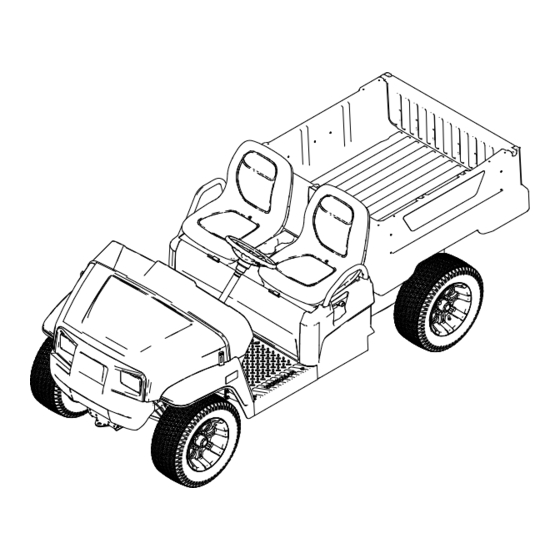
- Page 1 Form No. 3461-251 Rev A Workman ® GTX Lithium Utility Vehicle Model No. 07433LT—Serial No. 400000000 and Up Model No. 07433TC—Serial No. 400000000 and Up *3461-251* Register at www.Toro.com. Original Instructions (EN)
- Page 2 Whenever you need service, genuine Toro parts, or additional information, contact an Authorized Service Distributor or Toro Customer Service and have the model and serial numbers of your product ready.
-
Page 3: Table Of Contents
Contents Using the Battery-Disconnect Switch ....39 Servicing the Batteries........39 Maintaining the Lithium-Ion Batteries....39 Safety ............... 4 Maintaining the Battery Charger ....... 39 General Safety ........... 4 Locating the Fuses ........... 40 Safety and Instructional Decals ......5 Maintaining the Headlights ....... -
Page 4: Safety
Safety General Safety • This product is capable of causing personal injury or death. Always follow all safety instructions to avoid serious personal injury. • Improper operation, maintenance, or poor housekeeping of the machine may cause it to become unstable; other factors include terrain conditions, slope, speed, and poor operator judgment. -
Page 5: Safety And Instructional Decals
Safety and Instructional Decals Safety decals and instructions are easily visible to the operator and are located near any area of potential danger. Replace any decal that is damaged or missing. decal115-7739 115-7739 1. Falling, crushing hazard—do not carry passengers. decal139-4610 139-4610 1. - Page 6 decal144-0277 144-0277 1. Positive terminal 4. Do not dispose improperly. 2. Read the Operator’s 5. Do not expose to fire. Manual. 3. Recycle the battery. decal145-8016 145-8016 1. Read the Operator’s 4. Brake fluid Manual before performing maintenance. 2. Service interval (hours) 5.
- Page 7 decal147-8205 147-8205 1. 60 V plug 3. Bed lift 2. Electrical power decal145-5301 145-5301 1. Negative battery terminal decal145-5338 145-5338 1. Warning—read the Operator’s Manual. 4. Electric shock hazard—do not perform maintenance on the battery. 2. Warning—do not open the battery; do not use a damaged 5.
- Page 8 decal147-8184 147-8184 1. Headlights 6. Main system B+ 2. Alarm 7. Display power 3. USB power point 8. Horn 4. Read the Operator's Manual for fuse information. 9. Electrical shock hazard 5. DC to DC converter...
-
Page 9: Setup
Setup Loose Parts Use the chart below to verify that all parts have been shipped. Procedure Description Qty. Steering wheel Locknut Install the steering wheel (international models only). Wheel cover Screw – No parts required Charge the machine. – No parts required Check the fluid levels and tire pressure. -
Page 10: Charging The Machine
Use 3 screws to secure the wheel cover to the Check the transaxle-fluid level before you steering wheel. first start the machine; refer to Checking the Transaxle-Fluid Level (page 44). Torque the 3 screws to 0.6 N∙m (5 in-lb). Check the air pressure in the tires; refer to Checking the Tire Pressure (page 19). -
Page 11: Product Overview
Product Overview g319171 Figure 5 1. Hood latch 3. Cargo bed 5. Battery-charger outlet 2. Steering wheel 4. Towing tongue 6. Cargo-bed lever g319172 Figure 6 1. Passenger handhold 3. Trailer hitch 2. Parking-brake lever 4. Rear cargo-bed-accessory mount... -
Page 12: Controls
Controls Control Panel g435396 Figure 7 1. Horn switch 6. Parking-brake lever 2. Light switch 7. USB power point 3. Display 8. Accelerator pedal 4. Direction selector 9. Brake pedal 5. Key switch Accelerator Pedal Brake Pedal Use the accelerator pedal (Figure 7) to vary ground Use the brake pedal to stop or slow the machine. - Page 13 Parking-Brake Lever Horn Switch The parking-brake lever is located on the control The horn switch is located on the control panel (Figure panel (Figure 7). Press the horn switch to sound the horn. Whenever you shut off the machine, engage the parking brake to prevent the machine from accidentally Light Switch moving.
-
Page 14: Display
Display The display shows information about your machine, such as the operating status, various diagnostics, and other information about the machine (Figure 10). g413507 Figure 11 Startup screen 1. Software revision g320256 Figure 10 1. Indicator light 2. Display There is a startup screen, run screen, and charging screen on the display (Figure Figure... - Page 15 The run screen with the current machine speed (Figure 15) appears when you are driving the machine. g413589 Figure 13 Charging screen g415320 Figure 15 1. Battery life 3. Estimated time to fully charge the machine 1. Current machine speed 2.
- Page 16 When the cold battery indicator (Figure 17) appears, Icon Descriptions the machine performance changes until the battery temperature is above 0°C (32°F). Direction—F position ORWARD Direction—R position EVERSE Parking brake is engaged. Hour meter Battery voltage Battery charge level g424100 Battery currently charging Figure 17 1.
- Page 17 Supervisor Speed-Limit Switch Passenger Handholds The passenger handholds are located on the outside The supervisor speed-limit switch, located under the seat assembly, has 2 positions: P of each seat (Figure 19). ERFORMANCE and E . Rotate the switch clockwise to the CONOMY position to limit the maximum machine CONOMY...
-
Page 18: Specifications
28 cm (11 inches) inside Attachments/Accessories A selection of Toro approved attachments and accessories is available for use with the machine to enhance and expand its capabilities. Contact your Authorized Service Dealer or authorized Toro distributor or go to www.Toro.com for a list of all approved attachments and accessories. -
Page 19: Before Operation
Operation section (if applicable) in the • Use lower air pressure in the tires for lighter Installation Instructions. Visit www.Toro.com for your payloads, for less soil compaction, for a instructions or scan the QR code (if applicable) on smoother ride, and to minimize tire marks on your attachment. -
Page 20: Breaking In A New Machine
Breaking in a New Machine During Operation Service Interval: After the first 100 hours—Perform During Operation Safety the breaking in a new machine guidelines. Perform the breaking in a new machine guidelines General Safety to provide proper performance and long life for the •... - Page 21 • When using the machine on public roads, follow a rollover. Contact an authorized Toro distributor for all traffic regulations and use any additional more information. accessories that may be required by law, such as...
-
Page 22: Operating The Cargo Bed
Loading and Dumping Safety Pull the lever on left, inside of the cargo bed toward you and lift the cargo bed up (Figure 21). • Do not exceed the gross vehicle weight (GVW) of the machine when operating it with a load in the cargo bed and/or towing a trailer;... - Page 23 Raising the Cargo Bed to the Opening the Tailgate Service Position Ensure that the cargo bed is down and latched. Pull the lever on left, inside of the cargo bed Using both hands, raise the tailgate using the toward you and lift the cargo bed up (Figure 21).
-
Page 24: Monitoring The Battery-System Charge Level
Closing the Tailgate are operating at this battery percentage, drive the machine to a designated battery-charging area and If you unloaded loose material such as sand, charge the batteries; refer to Charging the Lithium-Ion landscaping rock, or wood chips from the cargo bed of Batteries (page 29). -
Page 25: After Operation
• Batteries could emit explosive gasses if they are Gravel, dry 1522 kg/m Full significantly overcharged. lb/ft • Refer to an authorized Toro distributor to service Gravel, wet 1922 kg/m (120 3/4 Full or replace a battery. lb/ft Sand, dry... -
Page 26: Hauling The Machine
1. Towing tongue and tie-down point (front of the machine) that is out of the reach of unauthorized users. • Do not disassemble the charger. Take the charger to an authorized Toro distributor when service or repair is required. • Unplug the power cord from the outlet before starting any maintenance or cleaning to reduce risk of electric shock. -
Page 27: Towing A Trailer
Toro distibutor for details. Never tow the machine at faster than 8 km/h When hauling cargo or towing a trailer, do not overload your machine or trailer. Overloading either (5 mph). -
Page 28: Transporting The Lithium-Ion Batteries
3-prong grounded plug (type B). If the plug does not fit into the wall receptacle, other grounded plug types 1. Charger outlet are available; contact an authorized Toro distributor. Do not change the charger or the power-supply-cord Insert the wall plug end of the power-supply cord plug in any way. - Page 29 Charging the Lithium-Ion Batteries CAUTION Attempting to charge the batteries with a charger not provided by Toro can result in excessive heat and other related product malfunctions, which can lead to property damage and/or injury. Use the Toro-provided chargers to charge the batteries.
-
Page 30: Maintenance
Maintenance or its use may result in injury or death. Such use could void the product warranty of The Toro® Company. Note: The procedures in this section show a machine with a plastic cargo bed and bucket seat; for additional procedures for other attachments, refer to the Maintenance section (if applicable) in the Installation Instructions. -
Page 31: Recommended Maintenance Schedule(S)
• Change the brake fluid. Every 1,000 hours Note: Download a free copy of the electrical schematic by visiting www.Toro.com and searching for your machine from the Manuals link on the home page. WARNING Failure to properly maintain the machine could result in premature failure of machine systems, causing possible harm to you or bystanders. -
Page 32: Daily Maintenance Checklist
Daily Maintenance Checklist Duplicate this page for routine use. Maintenance Check Item For the week of: Monday Tuesday Wednesday Thursday Friday Saturday Sunday Check the brake and parking brake operation. Check the direction-selector operation. Check the brake-fluid level. Check for unusual operating noises. -
Page 33: Pre-Maintenance Procedures
Pre-Maintenance Procedures WARNING Raise the cargo bed before performing maintenance. A raised cargo bed can fall and injure persons that are underneath it. • Always use the prop rod to hold the cargo g319293 bed up before working underneath it. Figure 29 •... -
Page 34: Raising And Lowering The Seat Assembly
g034045 Figure 31 g190066 Figure 32 Raise the hood. Removing a Bucket Seat Closing the Hood Gently lower the hood. Push the seat assembly forward to the raised position (Figure 32). Secure the hood by aligning the rubber latches onto the latch anchors on each side of the hood Slide the seat assembly to the side out of the (Figure 31). -
Page 35: Installing A Bucket Seat
Installing a Bucket Seat Installing a Bench Cushion Slide the seat assembly onto the pins and lower the Slide the bench cushion onto the pins and lower the seat assembly (Figure 34). cushion (Figure 36). g190186 Figure 34 1. Pins Removing a Bench Cushion Push the bench cushion forward to the raised g237190... -
Page 36: Lubrication
Lubrication Greasing the Front Wheel Bearings Service Interval: Every 300 hours Grease specification: Mobilgrease XHP™-222 Removing the Hub and Rotor Lift the front of the machine and support it with jack stands. Remove the 4 lug nuts that secure the wheel to the hub (Figure 37). - Page 37 Greasing the Wheel Bearings Remove the outboard bearing and bearing race from the hub (Figure 41). g192347 Figure 40 1. Spindle 2. Hub and rotor assembly g033050 Wipe clean the spindle with a rag. Figure 41 Repeat steps through to the hub and rotor at 1.
- Page 38 Installing the Hub and Rotor Apply a light coat of the specified grease to the spindle (Figure 42). g192345 Figure 43 g192344 1. Cotter pin 3. Dust cap Figure 42 2. Nut retainer 1. Nut retainer 4. Outer bearing 2. Spindle nut 5.
-
Page 39: Electrical System Maintenance
Toro distributor for assistance. Maintenance Do not open the battery. If you are having problems with a battery, contact your authorized Toro distributor for assistance. Electrical System Safety • Unplug the power cord before connecting or Maintaining the Lithium-Ion disconnecting the battery. -
Page 40: Locating The Fuses
• Coil the cords when not in use. • Periodically examine the cords for damage, and replace them when necessary with Toro-approved parts. Locating the Fuses The 12 V and 60 V fuses (Figure 45) are located under the hood. - Page 41 Adjusting the Headlights Use the following procedure to adjust the headlight beam position whenever a headlight assembly is replaced or removed. Park the machine on a level surface with the headlights approximately 7.6 m (25 ft) from a wall (Figure 48).
-
Page 42: Drive System Maintenance
Drive System Maintenance Maintaining the Tires Service Interval: Every 100 hours—Check the condition of the tires and rims. Every 100 hours—Torque the wheel-lug nuts. Inspect the tires and rims for signs of wear and damage. Note: Operating accidents, such as hitting curbs, can damage a tire or rim and also disrupt wheel alignment, so inspect tire condition after g415333... - Page 43 2 to 3 m (6 to 10 ft) and then straight forward to the original starting position. This allows the suspension to settle into the operating position. Adjusting the Camber Owner provided tools: spanner wrench, Toro Part 132-5069; refer to your authorized Toro distributor. Important: Make the camber adjustments only...
-
Page 44: Checking The Transaxle-Fluid Level
Checking the Transaxle-Fluid Level Service Interval: Every 100 hours—Check the transaxle-fluid level. Remove the fill plug on the transaxle (Figure 54). Note: The fluid level should be even with the bottom of the fill plug. g217834 Figure 55 1. Transaxle cover 2. -
Page 45: Brake Maintenance
Engage the parking brake by pulling the be worn and need to be replace. Contact your parking-brake lever toward you, until you feel authorized Toro distributor for assistance. tension. If you do not feel tension when pulling the Checking the Brake-Fluid parking-brake toward you within 11.4 to 16.5 cm... -
Page 46: Inspecting The Brakes
Replacing the Service and Parking-Brake Pads Service Interval: Every 400 hours Contact your authorized Toro distributor to inspect and possibly replace the service and parking-brake pads. Changing the Brake Fluid g002136 Service Interval: Every 1,000 hours/Every 5 years Figure 58 (whichever comes first)—Change... -
Page 47: Chassis Maintenance
Chassis Maintenance Cleaning Adjusting the Cargo-Bed Washing the Machine Latches Service Interval: Before each use or daily—Wash the machine. If the cargo-bed latch is out of adjustment, the cargo Wash the machine as needed using water alone bed vibrates up and down as you drive the machine. or with a mild detergent. -
Page 48: Storage
40% to 60%. If the charge is below 40%, charge the batteries between 40% to 60%. Note: Paint is available from your authorized • After charging the batteries, disconnect the battery Toro distributor. charger from power. Cover the machine to protect it and keep it clean. - Page 49 While the exposure from Toro products may be negligible or well within the “no significant risk” range, out of an abundance of caution, Toro has elected to provide the Prop 65 warnings. Moreover, if Toro does not provide these warnings, it could be sued by the State of California or by private parties seeking to enforce Prop 65 and subject to substantial penalties.
- Page 50 The Toro Company (“Toro”) respects your privacy. When you purchase our products, we may collect certain personal information about you, either directly from you or through your local Toro company or dealer. Toro uses this information to fulfil contractual obligations - such as to register your warranty, process your warranty claim or to contact you in the event of a product recall - and for legitimate business purposes - such as to gauge customer satisfaction, improve our products or provide you with product information which may be of interest.
- Page 51 Battery Limited Warranty Battery The rechargeable lithium-ion battery is warranted to be free from defects in materials and workmanship for a period of years as listed in the table below. Over time, battery consumption reduces the amount of energy capacity (Amp-hours) available per full charge. Energy consumption varies due to operating characteristics, accessories, turf, terrain, adjustments, and temperature.
- Page 52 Countries Other than the United States or Canada Customers who have purchased Toro products exported from the United States or Canada should contact their Toro Distributor (Dealer) to obtain guarantee policies for your country, province, or state. If for any reason you are dissatisfied with your Distributor's service or have difficulty obtaining guarantee information, contact your Authorized Toro Service Center.
Need help?
Do you have a question about the 07433LT and is the answer not in the manual?
Questions and answers