Table of Contents
Advertisement
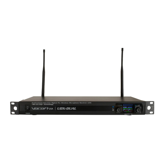
PROFESSIONAL DUAL UHF DIGITAL PLL MICROPHONE SYSTEM
POWER
I R
ANT-B
S E T U P
Receivers and Transmitters Sold Separately
UDX Series
ANT-1
CH-1
AF7
AF8
UHF Digital PLL Wireless Microphone System
921.40
927.60
with "Mic-on-Chip" Technology
MHz
CH - 3
S C A N
CH - 4
S C A N
Manual for all UDX receivers and Transmitters
255
76%
92%
OWNER'S MANUAL
7
8
S Y N C
UDX-GT9
UDX-GT3
UDX-DUAL
I R
I R
CH-2
S E T U P
S E T U P
CH-2
CH-3
CH-4
AF7
AF8
902.80
905.20
MHz
MHz
CH - 1
S C A N
CH - 2
033
92%
1
S Y N C
CHARGE
ANT
UDX-IT
UDX-CF
BALANCE OUT
I R
I R
MIX OUT
CH-1
MIX OUT
S E T U P
S E T U P
CH-5
CH-6
CH-7
MHz
S C A N
100%
2
MUTE
CH
UDX-BP
S E T U P
DC INPUT
RISK OF ELECTRONIC
UDX-DUAL
SHOCK! DO NOT OPEN!
I R
S E T U P
S E T U P
DC INPUT
MIC OUT
CH-8
MIX OUT
IR
CH 255
927.60
MHz
MUTE
CH
IR
909-928 MHZ
UDX-HT
I R
I R
S E T U P
CHANNEL 1-2
UDX-DUAL
CAUTION!
I R
I R
ANT-A
RF
S E T U P
1
AF
926.00
GR/CH
UDX-OCTO
MHz
SCAN
X:902.00MHz 3MHz/div
Y:REF-50dBm 20dB/div
44%
HI
ANT-2
POWER ON
OFF
Advertisement
Table of Contents

Related Manuals for VocoPro UDX Series


Summary of Contents for VocoPro UDX Series
- Page 1 S E T U P S E T U P S E T U P 926.00 GR/CH Receivers and Transmitters Sold Separately UDX-OCTO SCAN X:902.00MHz 3MHz/div Y:REF-50dBm 20dB/div UDX Series DC INPUT MIC OUT ANT-1 CH-1 CH-2 CH-3 CH-4 CH-5 CH-6...
-
Page 2: Legal Disclaimer
WELCOME And thank you for purchasing UDX Series from VocoPro. Along with quality products our commitment to customer satisfaction means we have technical support professionals ready to assist you. Be sure to visit our website- www.vocopro.com for the latest information on new products. -
Page 3: Listening For A Lifetime
Selecting fine audio equipment such as the unit you’ve just purchased is only the start of your musical enjoyment. Now it’s time to consider how you can maximize the fun and excitement your equipment offers. VocoPro and the Electronic Industries Association’s Consumer Electronics Group want you to get the most out of your equipment by playing it at a safe level. -
Page 4: Safety Instructions
Safety Instructions 10. Power Sources - The appliance should be connected to CAUTION a power supply only of the type described in the operating instructions or as marked on the appliance. RISK OF SHOCK 11. Grounding or Polarization - Precautions should be taken so that the grounding or polarization means of an appliance is not defeated. -
Page 5: Fcc Information
If these corrective measures do not produce satisfactory results, please contact your local retailer authorized to distribute Vocopro products. If you can not locate the appropriate retailer, please contact Vocopro, 1728 Curtiss Court, La Verne, CA 91750. -
Page 6: Table Of Contents
Table of Contents Legal Disclaimer ......................................Listening for a Lifetime ..................................Safety Instructions ....................................FCC Information ......................................Table of Contents ....................................... Functions and Descriptions 7-18 ............................... Getting Connected 19-20 ..................................Syncing the Transmitters to the Receiver 21-22 ........................Setting the Frequency on the Receiver 23-24 .......................... -
Page 7: Functions And Descriptions
Functions and Descriptions UDX-OCTO Receiver (Front) 1. Power Switch: Turns the receiver ON or OFF. 2. IR Sensor: When syncing a transmitter to any channel on the receiver, hold the IR sensor on the transmitter up to this IR sensor on the receiver to sync the frequency and pair the transmitter to a channel on the receiver. 3. - Page 8 Functions and Descriptions UDX-OCTO Receiver (Back) 1. Antenna Connection Jacks: Connect the TNC antenna to these jacks. 2. Channel 1-8 Balanced Outputs: Use these output jacks to get each channel audio on separate cables. 3. XLR Mix Out: Connect an XLR-female cable here to get all 8 channels together on a single cable. ¼...
- Page 9 Functions & Descriptions UDX-DUAL Receiver (Front) 1. Power Switch: Power system ON or OFF. 2. IR Sensor: When syncing a transmitter to any channel on the receiver, hold the transmitter IR sensor up to this IR sensor so that they are facing each other. The frequency will be synced and the transmitter will be paired with the selected channel.
- Page 10 Functions & Descriptions UDX-DUAL Receiver (Back) 1. Antenna Connector: Connect the TNC antenna to these jacks. 2. Balanced Outputs: Use these output jacks to get each channel audio on separate cables 3. Balanced Mix Out: Connect XLR cable here to get both channels through a single cable. 4.
- Page 11 Functions and Descriptions UDX-OCTO Receiver (Display) 1. AF Meter: Shows the audio signal strength being picked up by the transmitter. 2. Lock Icon: Indicates whether the two channels on that screen are locked or unlocked. When locked, you can adjust the volume or sync to those channels. When unlocked, you can change the frequency by selecting a new channel number or scanning for an open frequency.
- Page 12 Functions and Descriptions UDX-HT Handheld Microphone Transmitter 1. Microphone Capsule: Where the microphone picks up the sound. For the best reception, point the top of the microphone directly at the speaker’s mouth or other sound source. 2. Display & IR Sensor: The display shows the currently selected frequency and the battery life. It will also display MUTE when the mic is muted.
- Page 13 Functions and Descriptions UDX-BP Bodypack Transmitter 1. On/Mute/Off Power Switch: Use to turn the pack on or off. When the switch is in the middle position the pack will power on but be muted. 2. Volume Knob: Controls the audio level being sent to the receiver. Turn clockwise to increase volume. This control works independently from the volume control on the receiver.
- Page 14 Functions and Descriptions UDX-CF Conference Style Tabletop Transmitter and Gooseneck Microphone 1. Power/Mute Button: Press to turn the mic on. Press again to mute or unmute the mic. Hold to turn the mic off. 2. Display & IR Sensor: Shows the currently selected frequency and battery life, as well as a speaker symbol to show if the mic is muted or not.
- Page 15 Functions & Descriptions UDX-IT Transmitter 1. 15dB Pad: When switched to the left, decreases input volume by 15dB to help control loud sound sources. 2. IR Emitter: Face the emitter toward the IR Sensor on the receiver to sync frequencies. 3.
- Page 16 Features & Descriptions UDX-GT3 Transmitter 1. 15dB Pad: When switched to the left, decreases input volume by 15dB to help control loud sound sources. 2. IR Emitter: Face the emitter toward the IR Sensor on the receiver to sync frequencies. 3.
- Page 17 Features & Descriptions UDX-GT9 Transmitter 1. 15dB Pad: When switched to the left, decreases input volume by 15dB to help control loud sound sources. 2. IR Emitter: Face the emitter toward the IR Sensor on the receiver to sync frequencies. 3.
-
Page 18: Getting Connected
Getting Connected 1. Start by attaching the antenna to the receiver. The antenna will connect to the sockets on the back of the receiver labelled ANT-A and ANT-B. Screw the antenna on by twisting clockwise until they are tight. 2. Get the power adapter, connect the small end to the DC INPUT on the back of the receiver and plug the other end into a wall socket or power strip. - Page 19 DC INPUT Getting Connected MIC OUT ANT-1 CH-1 CH-2 CH-3 CH-4 CH-5 CH-6 CH-7 CH-8 MIX OUT ANT-2 DC INPUT Option 2: Using the XLR Mixed Out MIC OUT If you are connecting to a device that has XLR mic inputs, but does not have enough inputs for all of your ANT-1 CH-1 CH-2...
-
Page 20: Syncing The Transmitters To The Receiver
Syncing the Transmitters to the Receiver Once we have the receiver hooked up, we can begin syncing the transmitters to the different channels on the receiver. First, make sure all your transmitters have fresh, good quality batteries installed, and they are all powered on. Check the battery indicator on each transmitter. - Page 21 Syncing the Transmitters to the Receiver Once the transmitter and receiver are in range of each other, it will only take a second for them to pair. You can check that they are paired by looking at the receiver’s display. It should show that the RF meter is getting signal, the volume is not muted, you should be able to see the transmitter’s battery life, and if you speak into the microphone the AF meter will show signal.
-
Page 22: Setting The Frequency On The Receiver
Setting the Frequency on the Receiver When you first turn on the UDX-OCTO receiver, channels 1 through 8 will all be set to different frequencies. So you can go ahead and sync your transmitters to each channel, following the instructions in the previous section, and you should be good to go. - Page 23 Setting the Frequency on the Receiver Option 2: Setting a specific frequency Pick the channel you want to change. With the receiver powered on, push and hold the channel setup button until the screen is unlocked. Push the setup button so you have CH-# on the left highlighted in blue, and there is a channel number below. 902.80 905.20 CH - 1...
-
Page 24: Specifications
Specifications Receiver Adapter Rating: 12V-18V, ≥1.5A Operational Range: ~ 150 ft. w/ clear line of sight SNR: >90 dB Frequency Response: 40Hz - 20KHz Dynamic Range: 90dB Handheld Transmitter Capsule Type: Dynamic Battery: 2x AA 1.5V Alkaline Run Time: ~ 8 hours Bodypack Transmitter w/ Headset Mic Capsule Type: Condenser... -
Page 25: Troubleshooting
Troubleshooting Equipment is not turning on: For the Receiver: • Make sure the power adapter is securely connected to the receiver and to your outlet or power strip. • Check that the outlet or power strip is getting power, try plugging another device into the outlet. •... -
Page 26: Notes
Notes 26 \... -
Page 27: Limited Domestic Warranty
VocoPro warranty repair facility in U.S., or to the VocoPro, in the original packaging or a replacement supplied by VocoPro, with all transportation costs and full insurance paid each way by the purchaser or owner. - Page 28 TO VALIDATE YOUR WARRANTY: Fill out the attached warranty card, being sure to include the model and serial number of the unit since this is how warranty cards are tracked. If your VocoPro product was purchased in the U.S., mail the completed card directly to VocoPro within 10 days of the date of purchase.
- Page 29 LIMITED DOMESTIC WARRANTY Detach this portion and mail it to the factory MODEL MANUFACTURE DATE SERIAL NO. OWNER’S NAME ADDRESS CITY STATE The following information is appreciated, but not required: Dealer’s name and address: What other products and/or product changes would you like to see Manufactured? Any other comments: / 29...
- Page 30 Please do not return to the retailer if you are having a technical issue operating or connecting the unit. If you need additional help, have questions, or need support with your VocoPro product contact us: Toll Free: 800-678-5348 TEL: 909-593-8893 FAX: 909-593-8890 Email Tech Support at: techsupport@vocopro.com...
Need help?
Do you have a question about the UDX Series and is the answer not in the manual?
Questions and answers