
Related Manuals for VocoPro UHF-8900


Summary of Contents for VocoPro UHF-8900
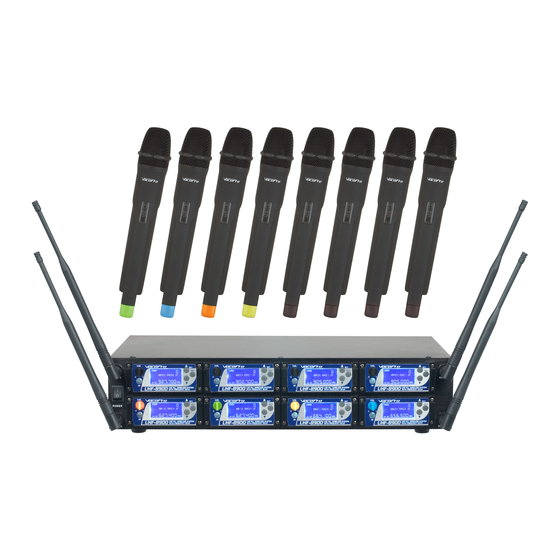
- Page 1 UHF-8900 UHF PLL WIRELESS MIC SYSTEM WITH FREQUENCY SCAN...
-
Page 2: Table Of Contents
Table of Contents Safety Instructions . . . . . . . . . . . . . . 3 FCC Information . . . . . . . . . . . . . . . . 4 Welcome . -
Page 3: Safety Instructions
Safety Instructions 8. Ventilation - The appliance should be situated so its location does not interfere with its proper ventilation. CAUTION For example, the appliance should not be situated on a bed, sofa, rug, or similar surface that may block the RISK OF SHOCK ventilation slots. -
Page 4: Fcc Information
1. To ensure the finest performance, please read this requirements. Modifications not expressly approved by manual carefully. Keep it in a safe place for future Vocopro may void your authority, granted by the FCC, reference. to use this product. 2. Install your unit in a cool, dry, clean place - away from 2. -
Page 5: Welcome
And while you're there don't forget to check out our Club VocoPro for Karaoke news and events, chat rooms, club directories and even a KJ Service directory! We look forward to hearing you sound like a PRO, with VocoPro, the singer’s ultimate choice. FOR YOUR RECORDS Please record the model number and serial number below, for easy reference, in case of loss or theft. -
Page 6: Listening For A Lifetime
Now itʼs time to consider how you can maximize the fun and excitement your equipment offers. VocoPro and the Electronic Industries Associationʼs Consumer Electronics Group want you to get the most out of your equipment by playing it at a safe level. One that lets the sound come through loud and clear without annoying blaring or distortion and, most importantly, without affecting your sensitive hearing. -
Page 7: Features
Features Features • 8 UHF PLL wireless microphones • Frequency scan feature finds interference-free channels • More than 150 wireless frequencies available • LCD display shows frequency and other info • 19” rack mountable chassis, uses just 2 rack spaces •... -
Page 8: Getting Connected
. 2 . Connect one end of an XLR cable to the Mixer CH.1 output of the UHF-8900. 3 . Connect the other end of the XLR cable to the desired input on your mixer. -
Page 9: Connecting Antennas
The UHF-8900 comes with detachable rack brackets which allows the unit to be installed in a standard 19 inch rack. 1. Use the included screws to fasten the rack brackets to the sides of the UHF-8900 as shown in the illustration below. -
Page 10: Descriptions And Functions
Descriptions and Functions Front Panel 1. Antenna Connector - Connect the antennas to these connectors to receive the wireless signals from the microphones. 2. Main Power Switch - This switch turns the power on and off for the whole unit. 3. -
Page 11: Rear Panel
Descriptions and Functions Module Display Window 1. MUTE Indicator - Displays when corresponding mic is off or disconnected. The Mute Mode is an automatic function. 2. Group and Channel - Displays the group and channel that the module is set to . *See Displaying the Group & Frequency page for details . - Page 12 Descriptions and Functions Microphones 1. IR (infrared) Sensor - This sensor receives the infrared signal that is used to set the frequency that the wireless mic will use. This sensor is only used to set the microphone frequency, it does not send or receive audio signal .
-
Page 13: Setting Up The Microphones
Setting up the Microphones Overview The goal is for each of the UHF-8900’s wireless channels to be operating on a frequency free of interference. This can be accomplished two ways 1) automatic frequency selection, and 2) manual frequency selection. We recommend using the automatic method first, as this method will work well for most areas. - Page 14 SCAN 3. Align the IR Sensors: Position the microphone so that the 2 IR sensors are level and within 3-5 inches of one another. UHF-8900 UHF PLL WIRELESS SYSTEM WITH FREQUENCY SCAN 4. Select Scan: Press the MENU button on the desired module twice (2x).
- Page 15 Setting the Frequencies Manually If the UHF-8900 is used in an area with heavy RF interference, it may be beneficial to set the frequencies manually. Please refer to the Advance Operation page to determine which frequencies to use for that area.
-
Page 16: Re-Syncing The Microphones
IR symbol. With the IR symbol DOWN displayed, press the SET button to communicate the existing frequency to the microphone. This will display UHF-8900 UHF PLL WIRELESS SYSTEM WITH FREQUENCY SCAN waves emanating from the IR symbol, when the waves disappear, the screen will display the existing frequency, as well as the AF and RF reception bars for that channel. -
Page 17: Using The Wireless Mics
Microphone Position The UHF-8900 is ideal for close-up vocals and can be held in the hand or mounted on a mic stand. Keep in mind that microphone technique is largely a matter of personal taste, and there is no one “correct” microphone position. -
Page 18: Basic Operations
Basic Operations Setting Up with Stage Monitors/P.A. System If you will be using the UHF-8900 with stage monitors and/or a P .A. system, try the following: • Place the stage monitor directly in front of the microphone . • Locate the P .A. loudspeakers so that they point away from the rear of the microphone. -
Page 19: Advanced Operations
Obtaining Local TV Tower Information The most common source of RF interference to the UHF-8900 is TV broadcast towers. If the UHF-8900 is experiencing dropouts, static, or other strange noises, it is likely RF interference at fault if within the threshold distance of 30 miles. -
Page 20: Frequency Reference
• Group: The Group number is the subset of frequencies to choose from in each module . The UHF-8900 displays the module in a few different ways The top Module row - The groups are listed sequentially starting from GR 01 through GR 05 . - Page 21 UHF-8900 Frequency List GR 1-1 GR 1-2 GR 1-3 GR 1-4 GR 05 GR 1-6 CH 01 614.000 615.000 616.300 614.000 620.000 626.000 CH 02 617.100 617.700 621.000 614.500 620.500 626.500 CH 03 621.200 623.300 627.000 625.200 621.200 627.200 CH 04 622.200...
- Page 22 TV Channel Frequencies (USA) 38 614-620 MHz 39 620-626 MHz 40 626-632 MHz 41 632-638 MHz 42 638-644 MHz 43 644-650 MHz 44 650-656 MHz 45 656-662 MHz 46 662-668 MHz 47 668-674 MHz 48 674-680 MHz 49 680-686 MHz 50 686-692 MHz 51 692-698 MHz...
-
Page 23: Troubleshooting
There is no power • Make sure the power adapter cord is firmly connected to the back of the UHF-8900 and to the power outlet. • If using a power strip/surge-protector, make sure that it is plugged in and switched on. - Page 24 UHF-8900 Owner’s Manual © VocoPro 2014 v1 .0 .0812 www.vocopro.com...
Need help?
Do you have a question about the UHF-8900 and is the answer not in the manual?
Questions and answers