
Related Manuals for Trotec SpeedMarker 700 CL


Summary of Contents for Trotec SpeedMarker 700 CL
- Page 1 SpeedMarker 700 CL Operating manual 8041 OM 8041_2.1_EN (01/2022) ENGLISH (Translation)
- Page 2 +31 850 70 51 55 +48 22 339 35 39 +52 55 5351-7252 support@troteclaser.nl serwis_pl@trodat.net mexico@troteclaser.com Trotec Laser (XIAMEN) CO., LTD. #5 GuAn Road South, MaXiang Trotec Laser Inc. Rubber Stamp & Engraving Town +1 866 226 8505, Option 2...
- Page 3 Trotec Laser GmbH Freilingerstraße 99 4614 Marchtrenk, Austria General contact to Technical Support: Tel.: +43 7242 239-7000 E-mail: techsupport@troteclaser.com WWW.TROTECLASER.COM...
- Page 4 Technical Changes Technical specifications are subject to change without notice. Trotec Laser GmbH reserves the right to improve or modify any of the products without prior notice. © Copyright This documentation with all illustrations is intellectual property of Trotec Laser GmbH. The entire documentation is given to the user for personal use only.
-
Page 5: Table Of Contents
Content Content Introduction........................8 General Information....................... 9 Information about this manual..........................9 2.1.1 Information about this manual..........................9 2.1.2 Storage of the manual............................. 9 2.1.3 General instructions for using the manual......................9 Explanation of symbols.............................10 Liability and warranty..............................10 Scope of delivery (standard configuration)......................11 Type plate..................................12 Safety........................... - Page 6 Content 5.3.1 System control.................................29 5.3.2 Laser rack..................................29 5.3.3 Industrial PC................................30 Safety devices................................30 Before commissioning....................33 Unloading, inspection and reporting faults......................33 Transport and Storage....................34 Transport conditions..............................34 Storage conditions..............................34 Place of storage................................34 Transport inspection and reporting of defects....................35 Setup and installation....................
- Page 7 Content Contact details......................57 Disassembly........................58 Disposal........................59 Appendix........................60 15.1 CE 8041 SpeedMarker 700 CL..........................61 15.2 Datasheet 8041 SpeedMarker 700 CL........................62...
-
Page 8: Introduction
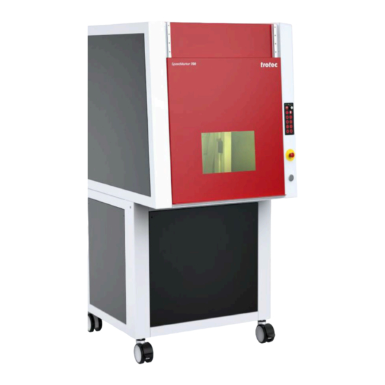
Introduction Introduction The Speedmarker 700 CL is a high quality Galvo marking laser. The use of a Ceramic-Core CO laser allows an extreme longevity with minimum maintenance. The combination of a high-quality galvo scanner and a Ceramic-Core CO laser allows short marking times with the highest precision of the marking. -
Page 9: General Information
General Information General Information Information about this manual 2.1.1 Information about this manual Before beginning any work on the machine, read this manual completely and carefully. Keep the manual for further consultation close to the machine. This manual describes how to operate the machine properly and safely. Be sure to follow the safety instructions given here, as well as any local accident prevention regulations and general safety regulations applicable to the field of usage. -
Page 10: Explanation Of Symbols
General Information Explanation of symbols Important technical safety notes and instructions in this manual are indicated by symbols. It is important to observe and follow these notes and instructions on workplace safety. Avoid accidents, personal injury and material damage to property by acting with extreme caution. -
Page 11: Scope Of Delivery (Standard Configuration)
Furthermore, Trotec Laser GmbH shall accept no liability whatsoever for damage caused by the use of non-original parts and accessories. Additionally, Trotec Laser GmbH shall not be held responsible for any personal injury or property damage, of an indirect or specific nature, consequential loss, loss of commercial profits, interruption to business, or loss of commercial information resulting from use of the equipment described in this manual. -
Page 12: Type Plate
General Information Type plate The type plate contains information regarding the serial number, manufacturer, date of manufacture, connection values and consumption data. The type plate is located on the reverse side of the laser machine. Enter the serial number, model and year of construction of the machine here. This data is important should the unit experience a fault and for ordering replacement parts. -
Page 13: Safety
Safety Safety TO AVOID POSSIBLE HARM READ AND FOLLOW THESE INSTRUCTIONS. The machine is built at the time of it's development and production according to applicable, established technical rules and is considered to be safe to operate. Dangers can be caused by the machine if the machine: is operated by unqualified personnel, •... -
Page 14: Intended Use
3.1.1 Intended use The SpeedMarker 700 CL is a Class 2 laser marker as per DIN EN 60825-1 "Safety of laser products". It is intended for integration in systems and lines. The product is intended exclusively for laser marking using the supplied marking soware. -
Page 15: Operating Modes
4 (US: class IV) and proper precautions need to be taken (see "Laser classification"). 3.1.6 Applicable safety regulations The following directives and guidelines must be observed to avoid hazards when operating Trotec laser systems: GUIDELINES/REGULATIONS 2006/42/EC... -
Page 16: Laser Safety
Laser classification The laser safety class indicates the risk potential based on the level of accessible laser radiation. The SpeedMarker 700 CL is a laser class 2 product and complies to the latest safety norms and regulations (IEC 60825-1). Class 1 The accessible laser radiation of Class 1 laser systems does not pose any hazard for the skin or eyes. - Page 17 Safety However, it is possible to suppress the natural eyelid closure reflex and stare into the class-2 laser beam for a time long enough for the eyes to get injured. Class 4 (US: class IV) Class 4 (US: class IV) high powered lasers (visible or invisible) considered to present potential acute hazard to the eye and skin for both direct and scatter (diffused) conditions.
-
Page 18: Areas Of Responsibility
Safety Areas of responsibility 3.3.1 Responsibilities of the operating company The operator has the following responsibilities: It is the responsibility of the operator to comply with the national official and statutory regulations for the operation • of a class 4 (US: class IV) laser system or laser system with a build in laser source of class 4 (US: class IV). In addition to the safety notes and instructions stated in this manual, consider and observe the local accident •... -
Page 19: Requirements For Operating An Service Personnel
The machine and its components, such as the lens and mirrors, are to be kept clean at all times. • Caution The adjustment of the beam path may only be carried out by service personnel of Trotec Laser GmbH. Requirements for operating an service personnel The requirements for the operating and service personnel are: The personnel must have read and understood this manual and in particular the "Safety"... - Page 20 Safety...
-
Page 21: Secondary (Indirect) Hazards
Safety Secondary (indirect) hazards 3.6.1 Fire hazard Warning Fire hazard Fire hazard from gas and processing of inflammable materials. – Do not operate the device without supervision. – Keep CO fire extinguisher ready at hand in the immediate vicinity of the device. If a main laser beam comes into contact with inflammable material, e.g. -
Page 22: In Case Of Emergency
• Notice Aer a deletion, Trotec Technical Support must be involved before the system is put back into operation. WHAT TO DO IN THE EVENT OF AN ACCIDENT, FIRST AID If eye damage occurs due to laser radiation (if the MPD values are exceeded), the casualty must present to an •... -
Page 23: Technical Data
Technical Data Technical Data The technical data sheet can be found in the appendix of this manual. Electrical requirements of the machine Laser power 60 W 100 W ~230 V ~230 V Voltage Fuse 16 A (T)* 16 A (T)* Power consumption 2240 W 2640 W... -
Page 24: Exhaust System Requirements
The requirements for the exhaust system and recommended Trotec exhaust systems for standard applications depend on the working table installed in the machine. - Page 25 Technical Data REQUIREMENTS FOR THE EXHAUST SYSTEM: Machine Volume flow [m³/h] Pressure [Pa] SpeedMarker 8500 The monitoring point for flow rate and pressure is at the exhaust port at the laser machine. Pressure loss by hoses / pipes or filter parts of the exhaust system has to be determined and additionally calculated when selecting a proper exhaust system.
-
Page 26: Machine Overview
Machine overview Machine overview General overview FRONT VIEW ❶ Observation window ❷ Safety door ❸ Rolls (optional levelling feet) ❹ Operating panel ❺ Monitor, keyboard, computer mouse ❻ Emergency stop button ❼ Start button SIDE VIEW RIGHT OR LEFT Protection cover Control rack Swivel arm for control unit Laser rack... -
Page 27: Machining Area
Machine overview BACK VIEW ❶ Connection Exhaust system ❷ Connection Power supply ❸ Connection Water cooling system SUPPLY CONNECTIONS The power cable can be connected via a power supply plug connection. Connect a suction hose with nominal diameter 70. Machining area The processing area is closed during the laser process. -
Page 28: Control Elements
Machine overview DRILLING PATTERN T-SLOT PLATE General structure of the axes The z-axis consists of a belt axis. • The z-axis is designed as a single axis. • The z-axis is driven by a precise servo motor. • The z-axis is limited by two electrical limit switches and a mechanical stop. •... -
Page 29: System Control
Machine overview 5.3.1 System control The system control takes over the control of the safety gate, the automatic sequence and the safety. ❶ Ventilation grille ❷ Main switch 5.3.2 Laser rack LASER RACK Number Description Types Main switch toggle switch System ready control lamp Shutter... -
Page 30: Industrial Pc
Machine overview 5.3.3 Industrial PC ❶ CD/DVD drive ❷ Ventilation grille Safety devices MAIN SWITCH Base cover on the right: When the main switch is operated, the entire system is de-energized. • Laser is off. • ❶ Main switch EMERGENCY STOP BUTTON 1. - Page 31 Machine overview Second priority: prevention of damage or destruction of machine or material. Immediately switch off the circuit. • Laser beam is interrupted by the shutter. • All movements are stopped. • The triggering of the emergency stop function is indicated by a fault message. •...
- Page 32 Machine overview SAFETY SWITCH ON THE SAFETY DOOR Observation window: The light blue observation window in the front door is made of a laser protection filter according to DIN EN 201, which is made of a special material that is adapted to the laser type and absorbs the laser radiation. If the window is damaged, it must be replaced.
-
Page 33: Before Commissioning
Record all details in writing immediately. • Note all claims on the transportation documents. • Photograph any damage. • Send report to Trotec Laser GmbH. • Nach dem Entladen: Remove all transport packaging. • Check the delivery for completeness. •... -
Page 34: Transport And Storage
Transport and Storage Transport and Storage Transport conditions When transporting outside, always transport in a covered vehicle or one with sufficient weather-proofing. • Protect the machine against transportation damage using straps and inserts, and leave sufficient distance between • other transported items. Ambient temperature for transportation: •... -
Page 35: Transport Inspection And Reporting Of Defects
Transport and Storage Transport inspection and reporting of defects Caution The lens unit cover should not be removed until aer installation. The optics are high-quality optical components whose perfect condition is necessary for an optimal marking result. Immediately aer receipt inspect the delivery to ensure that it is complete and has not suffered any damage. •... -
Page 36: Setup And Installation
Setup and installation Setup and installation For your safety Notice The setup has to be carried out by Technical Support. Temperature and humidity Ambiente conditions Operating temperature (ambiente temperature): +15 °C to +35 °C (59 °F to 95 °F) Relative humidity: max. -
Page 37: Unpacking The System
Setup and installation Unpacking the system REMOVE TRANSPORT PROTECTION: 1. Push up the high safety door ❶slightly. 2. Remove the screw of the fairing ❷on the le side. 3. Open the cover.. Caution Risk of crushing fingers! If necessary, close the cover carefully, paying attention to your fingers. 4. -
Page 38: Electrical Installation
Setup and installation LASER RACK AND PC The laser rack and the PC should be located next to or directly above one another if possible in order for the modules to be connected to one another with the cables provided. When installing in a control cabinet or rack, ensure there is sufficient ventilation. - Page 39 If no external panel is connected, the supplied connector must be used with the bridging devices. X61 – Exhaust system This connector is used to control, start and stop a Trotec extraction unit. Only use the original cable supplied. X71 – Start / Stop The X71 connector may be used to send start and stop signals via an external controller or receive a signal from the laser.
- Page 40 Setup and installation COM7/X Connection X-Axis COM8/Y Connection Y-Axis COM9/Z Connection Z-Axis COM10 Reserved COM11/B Connection B-Axis COM12/A Connection A-Axis Connection between PC and Laserrack Warning The maximum load of each of the digital 24V outputs on the interface is 100mA. A short circuit of the outputs must be avoided as it will damage the respective inputs.
- Page 41 Setup and installation The inputs have to be provided with a 5V - 24V potential. • For “ON”, the first PIN (e.g. PIN1) hast to be provided with 24V and the second PIN (e.g. PIN2) has to go to ground to •...
-
Page 42: Overview Pc Interface (Back Side)
Setup and installation APPLICATION EXAMPLES Input with switch and external 24V source at input "IN9". Supply of a lamp with 24V by activating "OUT10". 8.6.2 Overview PC interface (back side) The machine is connected to the Ethernet via a cable connection from the LAN interface on the rear of the PC rack to the LAN interface on the laser rack. -
Page 43: Interface Pin Configuration
Setup and installation The configuration of the laser rack is given on the type plate or on the warning label above the IEC connector. Warning Current The laser rack is fitted with different main fuses depending on the configured supply voltage: 115V AC 1 x 6.3 A "T"... - Page 44 Setup and installation X71 – Start / Stopp I/O Input/Output...
-
Page 45: Operation
Operation Operation Installation inspection The following points must be checked to ensure correct installation: Correct power supply connections and fuses. • Complete and correct mechanical and electrical installation. • Check that the mechanical and electrical installation is complete and correct Input voltages. •... -
Page 46: Control Elements
Operation Control elements ❶ LEDs ❷Keypad ❸Emergency stop button ❹ Start button Status Description POWER green Power supply is switched on green Laser control is switched on LASER green Laser is active ERROR Interference, not yet acknowledged AUTO green Automatic mode is active... - Page 47 Operation Key switch Selection of manual or automatic operation Button Lighting in the machining area Lighting Safety door open Move safety door upwards Safety door closed Move safety door down Button backward (Y) Move laser to the back Button right (X) Move laser to the right Button le...
-
Page 48: Manual Operation
Operation Manual operation MANUAL CONTROL OF SAFETY DOOR Button: Safety door open Button: Safety door closed SOFTWARE CONTROLLED Z-AXIS (OPTIONAL: Y-AXIS) (5) Button backward(Y) (8) Button forward (Y) (9) Button downwards (Z) (10) Button up (Z) – The axes are limited by limit switches. –... -
Page 49: Power On/Off
Operation Power On/Off 1. Press the main switch (1) on the laser rack. → The shutter is closed. The main switch and the two status lamps on the marking head illuminate in yellow. 2. Put the key in the key switch (7) (vertically) and turn 90° to the right. 3. -
Page 50: Focusing
Operation MEANING OF THE SIGNAL COLORS Emission indicator off - Device de-energised. Emission indicator status yellow - shutter is closed, no laser power output. Emission indicator staus red - shutter is open, output of laser power possible. Warning Laser If the device is switched on or the safety shutter is open there is a danger of laser radiation. - Page 51 Operation Working distance (A) Focal length F=150 152,6 mm F=200 205,6 mm F=300 305,6 mm F=400 404,6 mm...
-
Page 52: Maintenance
Maintenance Maintenance 10.1 Safety notes Caution Before any maintenance work takes place, ensure that the power supply has been switched off and the system is de-energised. Notice All maintenance work must be carried out according to the safety regulations. In order to ensure the maximum availability and lifetime of the system, we recommend you regularly check the filter system and ventilation and keep the surrounding area clean. -
Page 53: Cleaning The Optics
Maintenance 2. Remove both screws and open the cover. Change the filter pad. 10.3 Cleaning the optics This system is fitted with high quality optical components, which under normal operating conditions are maintenance free for their lifetime. However, it may be necessary to clean output lenses, e.g. the scanner flat field lens (f-theta objective) if it becomes covered in dust or fumes. -
Page 54: Troubleshooting
This chapter should assist maintenance personnel with the identification and resolution of operational faults based on error messages and symptoms. Danger Maintenance and repair work should only be carried out by Trotec Laser GmbH or one of its authorized personnel under observation of the safety regulations. 11.1... -
Page 55: Possible Error Messages
The Reset signal (X11) or the reset button on the laser rack are used to acknowledge an error. In order for the system to be reset, the error or the corresponding input signal must be acknowledged. Warning System errors which cannot be reset or which indicate a hardware error should only be resolved by Trotec Laser GmbH trained service personnel. Error message Cause Card off... - Page 56 Troubleshooting Error message Cause Required shutter position.
-
Page 57: Contact Details
Contact details Contact details TECHNICAL SUPPORT In case of questions, contact our experienced Technical Support in your local area. For global service contact numbers and further information please see our website, section "Support": www.troteclaser.com When calling, please make sure that the machine is in your immediate vicinity, and that you have the following information ready (see response form): At which working process did the problem occur? What you have done so far to correct the problem. -
Page 58: Disassembly
Disassembly Disassembly Warning Danger of injury when disassembling the machine. There is danger of injury when disassembling the machine. Always wear suitable protective clothing (e.g. safety goggles, safety shoes, safety gloves). Warning Current Electric current. The machine must be disconnected from the main power supply. Notice –... -
Page 59: Disposal
Disposal Disposal Disposal Do not dispose of the machine with domestic waste! Electronic devices have to be disposed of according to the regional directives on electronic and electric waste disposal. In case of further questions, please ask your supplier. In case of disassembly, use suitable tools to dismantle the unit into individual parts. Sort the individual parts and have them disposed of professionally. -
Page 60: Appendix
Appendix Appendix... -
Page 62: Datasheet 8041 Speedmarker 700 Cl
Technical Datasheet SpeedMarker 700 CO2... - Page 63 Technical Datasheet Technical Data SpeedMarker 700 CO2 Technical Data SpeedMarker 700 CO2 (8041) Workstation Configuration SM 0700 06C XXXX Z00 L00 SM 0700 10C XXXX Z00 L00 Norm CDRH Lasersafety; Laserclass 2; CE [EN 60825-1 (2015)] Software Speedmark; Directmark Printerdriver Supported mono fonts ISOCT, RomanS,SOKOL Supported fonts...
- Page 64 Technical Datasheet SM 0700 XXC FXX Z00 L00 Configuration SpeedMarker 700 with software-controlled z-axis and liquid cooling Interior top view Interior front view Front view Side view Tolerances on Dimensions: 1% Content subject to change without prior notice. Updated: February 2020...
Need help?
Do you have a question about the SpeedMarker 700 CL and is the answer not in the manual?
Questions and answers