Table of Contents
Advertisement
Quick Links
Advertisement
Table of Contents

Related Manuals for Trotec SpeedMarker 50 CL


Summary of Contents for Trotec SpeedMarker 50 CL
- Page 1 SpeedMarker 50 CL Operating Manual 8062 MA 8062_1.5_EN (11/2021) ENGLISH...
- Page 2 +31 850 70 51 55 +48 22 339 35 39 +52 55 5351-7252 support@troteclaser.nl serwis_pl@trodat.net mexico@troteclaser.com Trotec Laser (XIAMEN) CO., LTD. #5 GuAn Road South, MaXiang Trotec Laser Inc. Rubber Stamp & Engraving Town +1 866 226 8505, Option 2...
- Page 3 Trotec Laser Automation GmbH Planckstr. 12 88677 Markdorf Germany General Contact Technical Support Tel: +49 (0) 7544 9248-0 Email: techsupport@troteclaser.com WWW.TROTECLASER.COM...
- Page 4 Technical Changes Technical specifications are subject to change without notice. Trotec Laser GmbH reserves the right to improve or modify any of the products without prior notice. © Copyright This documentation with all illustrations is intellectual property of Trotec Laser GmbH. The entire documentation is given to the user for personal use only.
-
Page 5: Table Of Contents
Fire hazard................................26 3.6.2 Gases, fumes and dust............................26 3.6.3 Exhaust system................................ 26 In case of emergency..............................27 Technical Data......................28 Electrical requirements of the machine........................ 28 Connecting a cooling unit from Trotec Laser GmbH..................28 Before commissioning....................29 Unloading, inspection and reporting faults......................29... - Page 6 Content Transport and Storage....................30 Transport conditions..............................30 Storage conditions..............................30 Place of storage................................30 Setup and installation....................31 Installation conditions...............................31 7.1.1 Temperature and relative humidity........................31 Removal of packaging............................... 31 Mechanical installation............................. 34 7.3.1 Installation of the marking head......................... 34 Electrical installation..............................
- Page 7 Content Contact details......................58 Disassembly........................59 Disposal........................60 Appendix........................61 15.1 8062_Einbauerklärung_de............................62 15.2 Datasheet..................................63...
-
Page 8: General Information
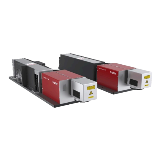
General Information The SpeedMarker 50 CL is an incomplete machine within the meaning of the EC Machinery Directive. The SpeedMarker 50 CL is a high-quality Galvo marking laser. Using a Ceramic-Core laser source enables an extremely long service life with minimal maintenance. -
Page 9: General Instructions For Using The Manual
General Information General instructions for using the manual The operating manual informs you about the correct and safe use of this machine and shows you the step-by-step actions required for initial start-up. The operating manual also contains important information on maintaining the system. -
Page 10: Applicable Health And Safety Requirements
General Information Notice This symbol indicates potential risks of damage to the supported product (or to property). In addition, non-observance may result in damage, malfunction or failure of the machine. Information This symbol indicates tips and information which must be observed for efficient and trouble-free handling of the product. - Page 11 General Information Basic health and safety requirements Applicable/ Fulfilled Notes valid 1.2.5 Selection of control or operating Partially The external devices for selecting the modes control or operating mode must meet the requirements 1.2.6 Power supply disruption 1.3. Protective measures against mechanical hazards 1.4 Requirements for safety devices 1.4.1 General requirements...
- Page 12 General Information Basic health and safety requirements Applicable/ Fulfilled Notes valid 1.5.13 Emission of dangerous materials Reference to DIN 60825:4 Annex D for laser and substances protection walls and to OStrV (Optical Radiation Regulation) and TROS laser radiation 1.5.14 Risk of being trapped in a machine 1.5.15 Risk of slipping, tripping and falling...
-
Page 13: Liability And Warranty
Furthermore, Trotec Laser GmbH shall accept no liability whatsoever for damage caused by the use of non-original parts and accessories. Additionally, Trotec Laser GmbH shall not be held responsible for any personal injury or property damage, of an indirect or specific nature, consequential loss, loss of commercial profits, interruption to business, or loss of commercial information resulting from use of the equipment described in this manual. -
Page 14: Type Plate
General Information Type plate The data plate contains information about the serial number, manufacturer, date of manufacture, connection values and consumption data. The data plate is located on the back of the laser rack. Enter the serial number, model and year of manufacture for the machine here. This data is important if there are problems with the machine and when ordering spare parts. -
Page 15: Laser Machine Hazards
Laser radiation damages the eye; depending on which wave length of the laser machine is used, different areas of the eye are primarily damaged. The following laser sources are used at Trotec Laser GmbH: = 10600 nm: This source is used in Speedy 100, 300, 360, 400 , SP500, SP 1500, SP 2000, SP 3000, SpeedMarker •... - Page 16 Laser machine hazards SKIN HAZARDS With class 4 laser machines, both direct radiation and indirect scattered radiation are dangerous and can cause skin and eye injuries. Tissue changes dependent on temperature Temperature in °C Effect (tissue change) < 40 Non-thermal effects 40-50 Enzymatic effects 60-65...
- Page 17 Laser machine hazards HAZARDS INCLUDE E.G.: Thermal decomposition produces smoke from selenium and zinc oxides. It is deposited as a white powder. Elemental selenium can also be deposited as a gray or red powder. There is a risk of poisoning if inhaled or swallowed. Given that the smoke is deposited on cold surfaces near the evaporation, there is only a risk of inhaling the smoke in the immediate temporal and spatial vicinity of the incident.
-
Page 18: Safety
3.1.1 Intended use The SpeedMarker 50 CL is a Class 4 marking laser as per DIN EN 60825-1 "Safety of laser products". It is only intended for integration in a laser protective housing. It is an incomplete machine within the meaning of the applicable Machinery Directive. -
Page 19: Improper Use
3.1.3 Temporal limits of the machine The SpeedMarker 50 CL has a service life of 10 years. Once the service life has been reached, the SpeedMarker must be fully serviced to ensure continued safe operation. Once the service life has been reached, all safety-relevant components must be replaced by a service technician from Trotec Laser GmbH and the general condition of the SpeedMarker 50 CL must be assessed. -
Page 20: Machine Modification
The service operation is therefore declared as laser class 4 and the appropriate precautions need to be taken (see "Laser classes"). 3.1.7 Applicable safety regulations The following guidelines and regulations are to be observed in order to avoid risks when operating Trotec laser systems. The following list is a non-exhaustive list. APPLIED GUIDELINES AND HARMONIZED STANDARDS 2006/42/EC... -
Page 21: Laser Safety
Laser classification The laser class according to EN 60825-1 describes the hazard potential emanating from accessible laser radiation. The SpeedMarker 50 CL is a laser class 4 product and complies with the latest safety norms and regulations (DIN EN 60825-1). - Page 22 Safety If there are covers attached to the housing that do not need to be monitored, they must be fastened in such a way that they can only be opened with a tool. Covers that are not monitored are only permitted if they are not required for maintenance or cleaning and have to be opened by the operator.
-
Page 23: Areas Of Responsibility
Safety Areas of responsibility 3.3.1 Operator’s obligations The operator has the following responsibilities: It is the operator’s responsibility to obtain information about and comply with any national legal requirements and • official regulations (e.g. reporting requirements) for the operation of laser systems of class 4 or laser systems with a built-in laser source of class 4. -
Page 24: Requirements For Operating An Service Personnel
The machine and its components, such as the lens and mirrors, are to be kept clean at all times. • Caution The adjustment of the beam path may only be carried out by service personnel of Trotec Laser GmbH. Requirements for operating an service personnel The requirements for the operating and service personnel are: The personnel must have read and understood this manual and in particular the "Safety"... - Page 25 Safety LABELS ON DELIVERY...
-
Page 26: Secondary (Indirect) Hazards
Safety Secondary (indirect) hazards 3.6.1 Fire hazard Warning Fire hazard There is a risk of fire due to gases and the processing of easily flammable materials. – Do not leave the machine unattended when in operation. – Keep a fire extinguisher selected in accordance with the fire report to hand and mount it in the immediate vicinity of the machine. -
Page 27: In Case Of Emergency
• Notice Aer a deletion, Trotec Technical Support must be involved before the system is put back into operation. WHAT TO DO IN THE EVENT OF AN ACCIDENT, FIRST AID If eye damage occurs due to laser radiation (if the MPD values are exceeded), the casualty must present to an •... -
Page 28: Technical Data
UPS (Uninterruptible Power Supply) or backup generator are required. When installing any of these devices, ensure that they meet the electrical requirements of the laser machine. Connecting a cooling unit from Trotec Laser GmbH Observe the operating and maintenance instructions in the operating manual for your cooling unit. -
Page 29: Before Commissioning
Record all details in writing immediately. • Note all claims on the transportation documents. • Photograph any damage. • Send report to Trotec Laser GmbH. • Nach dem Entladen: Remove all transport packaging. • Check the delivery for completeness. •... -
Page 30: Transport And Storage
Transport and Storage Transport and Storage Transport conditions When transporting outside, always transport in a covered vehicle or one with sufficient weather-proofing. • Protect the machine against transportation damage using straps and inserts, and leave sufficient distance between • other transported items. Ambient temperature for transportation: •... -
Page 31: Setup And Installation
Setup and installation Setup and installation Installation conditions 7.1.1 Temperature and relative humidity Operating temperature (ambient temperature): +15 °C to +35 °C (59 °F to 95 °F) Relative humidity: max. 60%, non-condensing AMBIENT CONDITIONS Sufficient lighting in the workplace. • Dust-free environment (class 2 IEC60947-1). - Page 32 Setup and installation TRANSPORT IN THE CRATE Warning Risk of injury due to slipping unit and falling parts! Improper procedure in transporting, loading and unloading the unit can lead to injury by falling parts and damage to the unit. Therefore: 1.
- Page 33 Setup and installation The unit is shipped in a crate, unless otherwise contractually agreed, and must be transported in the original packaging. No. Designation Symbol Fragile content Symbol Protect against moisture Symbol This way up Tilt monitoring (TiltWatch), see label for description. If the indicator is red, the limit was exceeded at least 1x during transport.
-
Page 34: Mechanical Installation
Setup and installation Mechanical installation 7.3.1 Installation of the marking head Correct, stable and reproducible alignment of the work head relative to the workpiece to be marked is a prerequisite for perfect marking results. Appropriate care must be taken when installing the work head. CENTER OF GRAVITY ATTACHMENT The laser assembly can be attached from below using the drilling template of the laser base plate with M8 screws... - Page 35 Setup and installation SpeedMarker with built-in laser source type TL4 and TL6: SpeedMarker with built-in laser source Type TL2 and TL3: ALIGNMENT The focal plane lies parallel to the base plate of the work head. When installing the marking head, make sure that the base plate of the work head is aligned as parallel as possible to the planned working level.
-
Page 36: Electrical Installation
Setup and installation Electrical installation 7.4.1 Overview SpeedMarker 50CL with built-in laser source Type TL4 SpeedMarker 50CL with built-in laser source Type TL2 and TL6: and TL3: Laser rack Power supply 230V AC,50/60 Hz, 1/N/PE Maximum power input 1800 W 7.4.2 Mains connection The back of the laser rack has an IEC socket for the supplied IEC cable. -
Page 37: Overview Laser Rack Interface (Back Side)
Setup and installation The machine is connected to the Ethernet via a cable connection from the LAN interface on the back of the PC rack to the LAN interface on the laser rack. THE FOLLOWING IP ADDRESSES ARE RESERVED: 192.168.0.3 192.168.0.10 192.168.0.13 192.168.0.16... - Page 38 If no external panel is connected, the supplied plug with the bridges must be used. X61 – Exhaust system This connection is used to control, start and stop a Trotec exhaust system. Only the supplied original cable may be plugged in here.
-
Page 39: Installation Without A Higher-Level Control System
Setup and installation 7.4.6 Installation without a higher-level control system X11 - SAFETY CIRCUIT (EMERGENCY STOP / INTERLOCK / EXTERNAL MESSAGES) X31 - EXTERNAL PANEL... -
Page 40: Installation With A Higher-Level Control System
Setup and installation X71 – START / STOP 7.4.7 Installation with a higher-level control system Switching sequences Switching sequence diagrams for various standard processes are listed here, which show the interaction of the individual levels. - Page 41 Setup and installation...
-
Page 42: Speedmark Ios
Setup and installation SpeedMark IOs The SpeedMarker 50CL has 4 digital inputs and 4 digital outputs, which can be used freely in SpeedMark. The inputs must be supplied with a 5V - 24V potential. • For “ON” the first PIN (e.g. PIN1) must be supplied with 24V and the second PIN (e.g. PIN2) has to go to ground in •... - Page 43 Setup and installation SPECIFICATION: Application example: Input with a switch and external 24V source at input “IN9”. Supply of a lamp with 24V by activating “OUT12”.
-
Page 44: Cooling
Setup and installation Cooling AIR COOLING The SpeedMarker 50CL is air-cooled with outputs of 30 watts, 45 watts and 60 watts. In the case of air-cooled systems, it must be ensured that the laser protection cabin has a sufficient amount of fresh air at a temperature of 20-25°C. - Page 45 Setup and installation Notice No condensation allowed. Polyethylene tubing with an external diameter of 0.5 inches is required for the “IN” and “OUT” connections. The cooling system can handle pressures of up to 4 bar (60 psi). The following materials are used in the cooling circuit of the laser machine: Delrin®...
-
Page 46: Control Of The Set-Up And Installation
Control of the set-up and installation Control of the set-up and installation To ensure correct installation, the following points must be checked: Correct power supply connection values and appropriate fuses. • Complete and correct execution of the mechanical and electrical installation. •... -
Page 47: Operation
Operation Operation Warning Laser When operating the laser system, the operator is exposed to laser class 4 within the laser protective housing. The direct and indirect scattered radiation is dangerous and can cause injuries to skin and eyes. – During service and adjustment of the laser machine, the operator is exposed to laser class 4 radiation. Wear suitable laser safety goggles, which are matched to the wavelength and power of the laser machine, within the danger zone. -
Page 48: Control Panel
Operation Control panel Number Description Types Main switch toggle switch System ready control lamp Shutter control lamp Laser busy control lamp Emergency stop button switch Error reset button Key switch switch Power On/Off 1. Press the main switch (1) on the laser rack. →... - Page 49 Operation 3. Press the Error reset button (6) to reset the system to its normal state. 4. The contrl lamps "System ready" (2) and "Shutter" (3) such as the status lamps on the marking head should now be illuminated. The laser is ready to start marking. 5.
-
Page 50: Operation/Standby Display
Operation Operation/Standby display The laser system is equipped with a two-stage operation/standby display. This is indicated by a separate display on the marking head and/or an illuminated warning light (shutter) on the laser rack. Meaning of the signal colors Operation/Standby display – Machine is de-energized. Operation/Standby display yellow –... - Page 51 Operation If the emergency stop doesn’t work correctly, the SpeedMarker 50CL must be put out of operation immediately until the error has been eliminated. MOVABLE GUARDS The function of the interlock must be checked at the start of each shi. When the movable guard is opened, the shutter must fall into the beam path.
-
Page 52: Focusing
Operation Focusing Notice It is absolutely essential to maintain the correct focal distance for every laser marking process. Only when in focus will the laser beam achieve the power density necessary for permanent and clearly legible marking. The correct focal distance between the marking head and the workpiece must therefore be set before each marking. An incorrect focal distance is the most common cause of poor or invisible marking. -
Page 53: Maintenance
Maintenance Maintenance 10.1 Safety notes Caution Before any maintenance work takes place, ensure that the power supply has been switched off and the system is de-energised. Notice All maintenance work must be carried out according to the safety regulations. In order to ensure the maximum availability and lifetime of the system, we recommend you regularly check the filter system and ventilation and keep the surrounding area clean. -
Page 54: Cleaning The Optics
Maintenance 2. Remove both screws and open the cover. Change the filter pad. 10.3 Cleaning the optics This system is fitted with high quality optical components, which under normal operating conditions are maintenance free for their lifetime. However, it may be necessary to clean output lenses, e.g. the scanner flat field lens (f-theta objective) if it becomes covered in dust or fumes. -
Page 55: Troubleshooting
This chapter should assist maintenance personnel with the identification and resolution of operational faults based on error messages and symptoms. Danger Maintenance and repair work should only be carried out by Trotec Laser GmbH or one of its authorized personnel under observation of the safety regulations. 11.1... -
Page 56: Possible Error Messages
Warning System errors which cannot be reset or which indicate a hardware error should only be resolved by Trotec Laser GmbH trained service personnel. Error message Cause Card is offline. - Page 57 Troubleshooting Error message Cause 24V monitoring. Shutter temperature. Required shutter position.
-
Page 58: Contact Details
Contact details Contact details TECHNICAL SUPPORT In case of questions, contact our experienced Technical Support in your local area. For global service contact numbers and further information please see our website, section "Support": www.troteclaser.com When calling, please make sure that the machine is in your immediate vicinity, and that you have the following information ready (see response form): At which working process did the problem occur? What you have done so far to correct the problem. -
Page 59: Disassembly
Disassembly Disassembly Warning Danger of injury when disassembling the machine. There is danger of injury when disassembling the machine. Always wear suitable protective clothing (e.g. safety goggles, safety shoes, safety gloves). Warning Current Electric current. The machine must be disconnected from the main power supply. Notice –... -
Page 60: Disposal
Disposal Disposal Disposal Do not dispose of the machine with domestic waste! Electronic devices have to be disposed of according to the regional directives on electronic and electric waste disposal. In case of further questions, please ask your supplier. In case of disassembly, use suitable tools to dismantle the unit into individual parts. Sort the individual parts and have them disposed of professionally. -
Page 61: Appendix
Appendix Appendix... -
Page 62: 8062_Einbauerklärung_De
EC Machinery Directive Appendix II 1A. Markdorf , May 31, 2021 Date i.A. Jochen Huber Electrical engineering www.troteclaser.com Trotec Laser Automation GmbH Planckstr. 12, 88677 Markdorf Germany www.trotec-materials.com... -
Page 63: Datasheet
Technical Datasheet SpeedMarker 50 CO2 Laser Marking System V004 subject to modifications / ‹1›... - Page 64 Technical Datasheet Technical Data SpeedMarker 50 CO2 (8062) Laser Head SM 0050 06C XXX F00 SM 0050 06C XXX L00 SM 0050 12C XXX L00 SM 0050 04C XXX F00 Norm CDRH Lasersafety; Laserclass 4 with EC- Declaration of Incorporation According to Machine Directive Software Speedmark;...
- Page 65 Technical Datasheet Machine dimensions SM 050 CO2 - laser marking head with lens configuration V004 subject to modifications / ‹3›...
- Page 66 Technical Datasheet V004 subject to modifications / ‹4›...
- Page 67 Technical Datasheet Laser marking head SM 0050 04C XXX F00 (without lenses) V004 subject to modifications / ‹5›...
- Page 68 Technical Datasheet Laser marking head SM 0050 06C XXX F00 (without lenses) V004 subject to modifications / ‹6›...
- Page 69 Technical Datasheet Laser marking head SM 0050 06C XXX L00 / SM 0050 12C XXX L00 (without lenses) V004 subject to modifications / ‹7›...
- Page 70 Technical Datasheet Laser Rack V004 subject to modifications / ‹8›...
- Page 71 Technical Datasheet Laser Controller IPC V004 subject to modifications / ‹9›...
Need help?
Do you have a question about the SpeedMarker 50 CL and is the answer not in the manual?
Questions and answers