Advertisement
Quick Links
www.ti.com
EVM User's Guide: LOG200EVM LOG200
LOG200 Evaluation Module
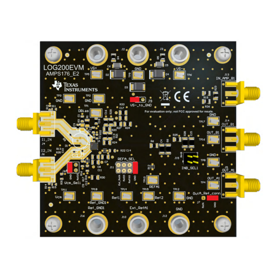
Description
The LOG200 evaluation module (EVM) is a
development platform for evaluating the LOG200,
which is a precision, high-speed logarithmic amplifier
with integrated photodiode bias and dark current
correction. The LOG200 is optimized for current
measurements across 160 dB wide dynamic range,
over several decades with unparalleled speed and
accuracy.
Features
•
High-accuracy logarithmic transfer function
•
Logarithmic ratio internally set to 250 mV/decade
of current-to-voltage conversion
•
Footprint for photosensor connection
SBOU301 – JULY 2023
Submit Document Feedback
•
Integrated photodiode bias and dark current
correction adaptive biasing circuit
•
Integrated precision 1 µA current reference
•
Integrated precision 1.65 V and 2.5 V voltage
references
•
Single supply (+5 V) or dual supply (±5 V)
operation
•
Sub-miniature version A (SMA) connectors and
test points allow for quick tests
Applications
•
Optical modules
•
Inter_DC interconnect
•
Optical network terminal unit
•
Chemistry/gas analyzer
LOG200EVM Hardware Board
Copyright © 2023 Texas Instruments Incorporated
Description
LOG200 Evaluation Module
1
Advertisement

Subscribe to Our Youtube Channel
Related Manuals for Texas Instruments LOG200EVM


Summary of Contents for Texas Instruments LOG200EVM
- Page 1 Description EVM User's Guide: LOG200EVM LOG200 LOG200 Evaluation Module • Integrated photodiode bias and dark current Description correction adaptive biasing circuit The LOG200 evaluation module (EVM) is a • Integrated precision 1 µA current reference development platform for evaluating the LOG200, •...
-
Page 2: Kit Contents
The LOG200 device integrates an uncommitted high-speed amplifier to allow the output to be configured for differential or filtered responses. The LOG200EVM operates over a 4.5 V to 12 V range unipolar supply or dual supply of ±2.25V to ±6 V supply. Table 2-2 for details. - Page 3 PCB traces that allow small currents to leak from the input traces or other sensitive nodes, degrading performance. For best performance, make sure to keep the LOG200EVM as clean as possible. The following list shows best practices to clean the evaluation board and to help prevent the EVM from becoming contaminated: •...
-
Page 4: Input And Output Connections
SMA connector J14, and test point TP16, located at the right side of the EVM. For a full schematic of the LOG200EVM, see Figure 3-1 Figure 3-2. Table 2-1 summarizes the input and output connectors and corresponding test points. Table 2-1. LOG200EVM Input and Output Connections Designator Signal Connector Type Description I1_IN Current input for logarithm numerator... -
Page 5: Power Requirements
The power-supply connections for the LOG200EVM are provided through standard banana jack connectors J1, J2, and J3 at the top of the EVM. The LOG200EVM can be set up with a single unipolar supply or with dual bipolar supplies by setting jumper J9. -
Page 6: Jumper Information
Hardware www.ti.com 2.4 Jumper Information Figure 2-2 details the default jumper settings of the LOG200EVM. Table 2-3 explains the configuration for these jumpers. Figure 2-2. LOG200EVM Default Jumper Settings Table 2-3. Default Jumper Configuration Jumper Function Default Position Description Out_A... - Page 7 Hardware 2.5 Optional Photodiode Connections The LOG200EVM PCB board layout includes a photosensor footprint (D1) to install a radial photodiode on current input I1 for the logarithmic numerator. See Figure 2-3 for the photosensor input and photosensor biasing connections.
- Page 8 Pin16_Vcm2 VCM2 REFA_Sel Pin10_RefA TP15 REFA Pin5_Ref25 Ref2 REF25 Pin9_Ref165 Pin6_RefGND REF165 REFGND LOG200RGT Note: DNP components are not populated. Figure 3-1. LOG200EVM Schematic LOG200 Evaluation Module SBOU301 – JULY 2023 Submit Document Feedback Copyright © 2023 Texas Instruments Incorporated...
- Page 9 10uF Pin9_Ref165 10uF 100V 330pF 100nF VS-_to_GND Ref_GND1 TP18 100nF Pin6_RefGND 100nF Pin17_Pad Ref_GND1 Note: DNP components are not populated. Figure 3-2. LOG200EVM Schematic SBOU301 – JULY 2023 LOG200 Evaluation Module Submit Document Feedback Copyright © 2023 Texas Instruments Incorporated...
-
Page 10: Pcb Layout
The LOG200EVM provides a footprint to connect a photodiode to the I1 input pin. The photosensor is kept in close proximity to the I1 input to minimize parasitic capacitance. The evaluation board provides all the necessary photosensor and adaptive bias circuit connections through resistor R2, R3 and optional capacitors C1, C3. - Page 11 Hardware Design Files Figure 3-4. Top Layer PCB Layout Figure 3-5. Mid Layer 1 PCB Layout SBOU301 – JULY 2023 LOG200 Evaluation Module Submit Document Feedback Copyright © 2023 Texas Instruments Incorporated...
- Page 12 Hardware Design Files www.ti.com Figure 3-6. Mid Layer 2 PCB Layout Figure 3-7. Bottom Layer PCB Layout LOG200 Evaluation Module SBOU301 – JULY 2023 Submit Document Feedback Copyright © 2023 Texas Instruments Incorporated...
-
Page 13: Bill Of Materials (Bom)
Hardware Design Files 3.3 Bill of Materials (BOM) Table 3-1 lists the LOG200EVM bill of materials (BOM). Table 3-1. LOG200EVM Bill of Materials Package Designator Value Description Part Number Manufacturer Reference !PCB1 Printed Circuit Board AMPS176 C2, C9 1000 pF CAP, CERM, 1000 pF, 50 V,+/- 5%,... -
Page 14: Additional Information
Additional Information www.ti.com Table 3-1. LOG200EVM Bill of Materials (continued) Package Designator Value Description Part Number Manufacturer Reference TP1, TP2, TP3, Test Point, Compact, SMT 5016 Keystone TP4, TP5, TP6, TP8, TP9, TP10, TP11, TP12, TP14, TP15, TP16, TP17, TP18... - Page 15 STANDARD TERMS FOR EVALUATION MODULES Delivery: TI delivers TI evaluation boards, kits, or modules, including any accompanying demonstration software, components, and/or documentation which may be provided together or separately (collectively, an “EVM” or “EVMs”) to the User (“User”) in accordance with the terms set forth herein.
- Page 16 www.ti.com Regulatory Notices: 3.1 United States 3.1.1 Notice applicable to EVMs not FCC-Approved: FCC NOTICE: This kit is designed to allow product developers to evaluate electronic components, circuitry, or software associated with the kit to determine whether to incorporate such items in a finished product and software developers to write software applications for use with the end product.
- Page 17 www.ti.com Concernant les EVMs avec antennes détachables Conformément à la réglementation d'Industrie Canada, le présent émetteur radio peut fonctionner avec une antenne d'un type et d'un gain maximal (ou inférieur) approuvé pour l'émetteur par Industrie Canada. Dans le but de réduire les risques de brouillage radioélectrique à...
- Page 18 www.ti.com EVM Use Restrictions and Warnings: 4.1 EVMS ARE NOT FOR USE IN FUNCTIONAL SAFETY AND/OR SAFETY CRITICAL EVALUATIONS, INCLUDING BUT NOT LIMITED TO EVALUATIONS OF LIFE SUPPORT APPLICATIONS. 4.2 User must read and apply the user guide and other available documentation provided by TI regarding the EVM prior to handling or using the EVM, including without limitation any warning or restriction notices.
- Page 19 Notwithstanding the foregoing, any judgment may be enforced in any United States or foreign court, and TI may seek injunctive relief in any United States or foreign court. Mailing Address: Texas Instruments, Post Office Box 655303, Dallas, Texas 75265 Copyright © 2023, Texas Instruments Incorporated...
- Page 20 TI products. TI’s provision of these resources does not expand or otherwise alter TI’s applicable warranties or warranty disclaimers for TI products. TI objects to and rejects any additional or different terms you may have proposed. IMPORTANT NOTICE Mailing Address: Texas Instruments, Post Office Box 655303, Dallas, Texas 75265 Copyright © 2023, Texas Instruments Incorporated...
Need help?
Do you have a question about the LOG200EVM and is the answer not in the manual?
Questions and answers