Table of Contents
Advertisement
Quick Links
Advertisement
Table of Contents

Related Manuals for Gigabyte W753-W50


Summary of Contents for Gigabyte W753-W50
- Page 1 W753-W50 Intel® Xeon® W7 GPU Workstation User Manual Rev. 1.0...
- Page 2 GIGABYTE's prior written permission. Documentation Classifications In order to assist in the use of this product, GIGABYTE provides the following types of documentation: User Manual: detailed information & steps about the installation, configuration and use of this product (e.g.
- Page 3 Conventions The following conventions are used in this user's guide: NOTE! Gives bits and pieces of additional information related to the current topic. CAUTION! Gives precautionary measures to avoid possible hardware or software problems. WARNING! Alerts you to any damage that might result from doing or not doing specific actions.
- Page 4 Warnings and Cautions Before installing, be sure that you understand the following warnings and cautions. WARNING! To reduce the risk of electric shock or damage to the equipment: • Do not disable the power cord grounding plug. The grounding plug is an important safety feature.
- Page 5 Electrostatic Discharge (ESD) CAUTION! ESD CAN DAMAGE DRIVES, BOARDS, AND OTHER PARTS. WE RECOMMEND THAT YOU PERFORM ALL PROCEDURES AT AN ESD WORKSTATION. IF ONE IS NOT AVAILABLE, PROVIDE SOME ESD PROTECTION BY WEARING AN ANTI-STATIC WRIST STRAP AT- TACHED TO CHASSIS GROUND -- ANY UNPAINTED METAL SURFACE -- ON YOUR SERVER WHEN HANDLING PARTS.
- Page 6 CAUTION! Risk of explosion if battery is replaced incorrectly or with an incorrect type. Replace the battery only with the same or equivalent type recommended by the manufacturer. Dispose of used bat- teries according to the manufacturer’s instructions.
- Page 7 GIGABYTE products have not intended to add and safe from hazardous substances (Cd, Pb, Hg, Cr+6, PBDE and PBB). The parts and components have been carefully selected to meet RoHS requirement. More- over, we at GIGABYTE are continuing our efforts to develop products that do not use internationally banned toxic chemicals.
- Page 8 Ra ng 100-240V~, 12-6A, 50-60Hz Opera ng Temperature 10°C to 35°C Non-opera ng temperature -40°C to 60°C Opera ng humidity 8%-80% (non-condensing) Non-opera ng humidity 20%-95% (non-condensing) 伺服器相關警告與注意事項 警告 為了避免電擊危險或損壞設備請注意: • 不要切斷電源線的接地端子,接地端子是一個很重要的安全防護。 • 將電源線接到有接地功能的插座,此插座需位於使用者容易使用的範圍。 • 電源線的配線要避免被踩到,被絆到或被過度彎折,重壓。 警告 • 本設備關機後內部仍存在電源,須拔掉電源線才能完全切掉設備內部的電源。 • 更換零件前請確定電源已經完全切斷。 •...
- Page 9 警告 • 如果更換錯誤電池會產生爆炸,請以相同或同型號電池更換使用。 • 廢電池請回收。 注意 • 伺服器開機時不要長時間移除蓋子,長時間移除蓋子會造成散熱功能失效造成損壞。 注意 • 靜電會損害電子產品,建議您在符合靜電防護的工作環境操作伺服器,如果無法確定 環境的靜電防護。請穿上靜電手環並且將手環接到有接地的金屬表面如機櫃或機殼。 • 拿取電路板時僅觸碰板子的邊緣,不要觸碰連接器。板子從防靜電包裝取出後只能放 置在無靜電的桌面,零件面朝上。如果可以, 請使用防靜電泡棉. 避免使用靜電袋. 避免 電路板與任何表面摩擦產生靜電。...
-
Page 10: Table Of Contents
Table of Contents Chapter 1 Hardware Installation ...................13 Installation Precautions .................. 13 Product Specifications ..................14 System Block Diagram ................... 17 Chapter 2 System Appearance ..................18 Front View ...................... 18 Rear View ....................... 19 Rear Panel System LAN LEDs ..............20 Chapter 3 System Hardware Installation ..............21 Removing and Installing the Chassis Cover .......... - Page 11 5-2-11 iSCSI Configuration ....................53 5-2-12 Intel(R) Ethernet Controller X710 for 10GBASE-T ..........54 5-2-13 VLAN Configuration ....................56 5-2-14 Driver Health ......................57 Chipset Menu ....................58 5-3-1 Processor Configuration ..................59 5-3-2 Common RefCode Configuration ................62 5-3-3 UPI Configuration ....................63 5-3-4 Memory Configuration ....................64 5-3-5 IIO Configuration ....................67 5-3-6...
-
Page 12: Chapter 1 Hardware Installation
Chapter 1 Hardware Installation Installation Precautions The motherboard/system contain numerous delicate electronic circuits and components which can become damaged as a result of electrostatic discharge (ESD). Prior to installation, carefully read the user manual and follow these procedures: • Prior to installation, do not remove or break motherboard S/N (Serial Number) sticker or warranty sticker provided by your dealer. -
Page 13: Product Specifications
Product Specifications NOTE: We reserve the right to make any changes to the product specifications and product-related information without prior notice. System Pedestal Š 726.3 x 218 x 455 mm Dimension Š Motherboard MW53-HP0 Š Intel® Xeon® W-2400 Processors Š Single processor, TDP up to 225W Š... - Page 14 Expansion Slot Slot_7: 1 x PCIe x16 (Gen5 x16 bus) slot, from CPU Š Slot_6: 1 x PCIe x16 (Gen5 x16 bus) slot, from CPU Š Slot_5: 1 x PCIe x16 (Gen5 x16 bus) slot, from CPU Š Slot_4: 1 x PCIe x16 (Gen5 x16 bus) slot, from CPU Š...
- Page 15 Š +12V/ 100A +5V/ 20A +5Vsb/ 3A +3.3V/ 20A System ASPEED® AST2600 Management Controller Š Management GIGABYTE Management Console (AMI MegaRAC SP-X) web interface Š Š Dashboard Š HTML5 KVM Š Sensor Monitor (Voltage, RPM, Temperature, CPU Status …etc.) Š...
-
Page 16: System Block Diagram
System Block Diagram Hardware Installation - 17 -... -
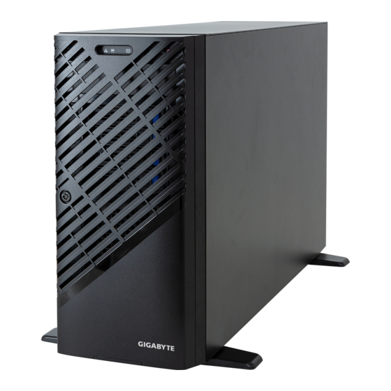
Page 17: Chapter 2 System Appearance
Chapter 2 System Appearance Front View No. Description Description USB 3.2 Gen1 Reset System LED Power Button HDD LED Earphone Power LED System Appearance - 18 -... -
Page 18: Rear View
Rear View No. Description Description VGA/COM Port MIC-IN (Pink) USB 3.2 Ports (Type C) LINE-OUT (Green) 2.5Gbe LAN LINE-IN (Blue) USB 3.2 Ports (Type A) PCIe Card Bay MLAN PSU (AC 110V - 240V) The HDMI port is HDCP 2.3 compliant and supports Dolby TrueHD and DTS HD Master Audio formats. It also supports up to 192KHz/24bit 7.1-channel LPCM audio output. -
Page 19: Rear Panel System Lan Leds
Rear Panel System LAN LEDs Name Color Status Description Yellow 1 Gbps data rate 2.5GbE Green 2.5 Gbps data rate Speed LED 10 Mbps data rate Link between system and network or no access Green 1GbE Link / Blink Data transmission or reception is occurring. Activity LED No data transmission or reception is occurring. -
Page 20: Chapter 3 System Hardware Installation
Chapter 3 System Hardware Installation Pre-installation Instructions Computer components and electronic circuit boards can be damaged by electrostatic discharge. Working on computers that are still connected to a power supply can be extremely dangerous. Follow the simple guidelines below to avoid damage to your computer or injury to yourself. -
Page 21: Removing And Installing The Chassis Cover
Removing and Installing the Chassis Cover Before you remove or install the chassis cover • Make sure the system is not turned on or connected to AC power. Follow these instructions to remove/install the chassis side cover and front bezel: Remove the screw securing the chassis side cover. -
Page 22: Installing The Cpu
Installing the CPU Read the following guidelines before you begin to install the CPU: • Make sure that the motherboard supports the CPU. • Always turn off the computer and unplug the power cord from the power outlet before installing the CPU to prevent hardware damage. -
Page 23: Installing The Memory
Installing the Memory Read the following guidelines before you begin to install the memory: • Make sure that the motherboard supports the memory. It is recommended that memory of the same capacity, brand, speed, and chips be used. • Always turn off the computer and unplug the power cord from the power outlet before installing the memory to prevent hardware damage. -
Page 24: Installing The Memory
3-3-2 Installing the Memory Before installing a memory module, make sure to turn off the computer and unplug the power cord from the power outlet to prevent damage to the memory module. Be sure to install DDR5 DIMMs on this motherboard. Follow these instructions to install the Memory: Insert the DIMM memory module vertically into the DIMM slot, and push it down. -
Page 25: Installing The Pci Expansion Card
Installing the PCI Expansion Card • Voltages can be present within the server whenever an AC power source is connected. This voltage is present even when the main power switch is in the off position. Ensure that the system is powered-down and all power sources have been disconnected from the server prior to installing a PCIe card. -
Page 26: Installing The Hard Disk Drive
Slide the first hard disk drive into the slot. Mount it with two screws on each side. Slide the second hard disk drive into the dedicated HDD tray. (Note: Connect your GIGABYTE sales representative with any order requests.) Screw the hard disk drive with four screws. -
Page 27: Installing And Removing The M.2 Ssd Module
Installing and Removing the M.2 SSD Module Follow the steps below to install an optional M.2 SSD module on your motherboard. Step1. Insert the M.2 SSD module into the slot. Step2. Secure it with the screw, tightening as necessary to fasten the M.2 SSD module in place. Installing and Removing the M.2 WiFi Module Follow the steps below to install a M.2 WiFi module on your motherboard. -
Page 28: Peripheral Devices Connection
Peripheral Devices Connection System Hardware Installation - 29 -... -
Page 29: Chapter 4 Motherboard Components
Chapter 4 Motherboard Components Motherboard Components 13 12 Motherboard Components - 30 -... - Page 30 Item Description Audio Connectors Sever Management LAN Port (Top)/USB 3.2 Gen2 Type A Ports (Bottom) 10GbE LAN Port #1 / USB 3.2 Gen2 Type-A Ports 10GbE LAN Port #2 / USB 3.2 Gen2 Type-A Ports + Type-C Port Serial Port (Top)/VGA Port (Bottom) ID Button with LED 2x4 Pin 12V Power Connector 2x12 Pin Main Power Connector...
-
Page 31: Jumper Setting
Jumper Setting Enable Default BIOS Default Enable Force Recovery 3 2 1 Update BIOS_RCVR ME_UPDATE Password Default Clear Enable BIOS_PWD Default Clear CMOS Enable CLR_CMOS Motherboard Components - 32 -... -
Page 32: Chapter 5 Bios Setup
Chapter 5 BIOS Setup BIOS (Basic Input and Output System) records hardware parameters of the system in the EFI on the motherboard. Its major functions include conducting the Power-On Self-Test (POST) during system startup, saving system parameters, loading the operating system etc. The BIOS includes a BIOS Setup program that allows the user to modify basic system configuration settings or to activate certain system features. - Page 33 Main This setup page includes all the items of the standard compatible BIOS. Advanced This setup page includes all the items of AMI BIOS special enhanced features. (ex: Auto detect fan and temperature status, automatically configure hard disk parameters.) ...
-
Page 34: The Main Menu
The Main Menu Once you enter the BIOS Setup program, the Main Menu (as shown below) appears on the screen. Use arrow keys to move among the items and press <Enter> to accept or enter other sub-menu. Main Menu Help The on-screen description of a highlighted setup option is displayed on the bottom line of the Main Menu. - Page 35 Parameter Description BIOS Information Project Name Displays the project name information. Project Version Displays version number of the BIOS setup utility. Build Date and Time Displays the date and time when the BIOS setup utility was created. BMC Information (Note1) BMC Firmware Version Displays BMC firmware version information.
- Page 36 Parameter Description Memory Frequency Displays the frequency information of the installed memory. Onboard LAN Information (Note3) LAN# MAC Address Displays LAN MAC address information. System Date Sets the date following the weekday-month-day-year format. System Time Sets the system time following the hour-minute-second format. (Note3) The number of LAN ports listed will depend on the motherboard / system model.
-
Page 37: Advanced Menu
Advanced Menu The Advanced Menu displays submenu options for configuring the function of various hardware components. Select a submenu item, then press <Enter> to access the related submenu screen. BIOS Setup - 38 -... -
Page 38: Trusted Computing
5-2-1 Trusted Computing Parameter Description TPM 2.0 Device Found Firmware Version/ Vendor Displays the firmware version and Vendor information. Enable/Disable BIOS support for security device. OS will not show security device. TCG EFI protocol and INT1A interface will not be TPM v1.2 Support available. - Page 39 Parameter Description Schedule an operation for the security device. NOTE: Your computer will reboot during restart in order to change the Pending operation state of a security device. Options available: None, TPM Clear. Default setting is None. Enable/Disable platform hierarchy. Platform Hierarchy Options available: Disabled, Enabled.
-
Page 40: Serial Port Console Redirection
5-2-2 Serial Port Console Redirection Parameter Description Console redirection enables the users to manage the system from a COM1 Console remote location. Redirection (Note) Options available: Enabled, Disabled. Default setting is Disabled. Press [Enter] to configure advanced items. Please note that this item is configurable when COM1 Console Redirection is set to Enabled. - Page 41 Parameter Description Parity Š – A parity bit can be sent with the data bits to detect some transmission errors. – Even: parity bit is 0 if the num of 1's in the data bits is even. – Odd: parity bit is 0 if num of 1's in the data bits is odd. –...
- Page 42 Parameter Description Serial Port for Out-of-Band Management / Windows EMS console redirection allows the user to configure Console Redirection Emergency Management Settings to support Out-of-Band Serial Port management. Services (EMS) Console Options available: Enabled, Disabled. Default setting is Disabled. Redirection (Note) Press [Enter] to configure advanced items.
-
Page 43: Sio Configuration
5-2-3 SIO Configuration Description Parameter Displays the AMI SIO driver version information. AMI SIO Driver Version Super IO Chip Logical Device(s) Configuration Press [Enter] to configure advanced items. Use This Device Š – When set to Enabled allows you to configure the serial port settings. When set to Disabled, displays no configuration for the serial port. -
Page 44: Pci Subsystem Settings
5-2-4 PCI Subsystem Settings BIOS Setup - 45 -... - Page 45 Parameter Description PCI Bus Driver Version Displays the PCI Bus Driver version information. When enabled, this setting will initialize the device expansion PCIE_# I/O ROM ROM for the related PCI-E slot. (Note1) Options available: Enabled, Disabled. Default setting is Enabled. PCIE_# Lanes Change the PCIe lanes.
-
Page 46: Usb Configuration
5-2-5 USB Configuration Parameter Description USB Configuration USB Devices: Displays the USB devices connected to the system. Enable/Disable the XHCI (USB 3.0) Hand-off support. XHCI Hand-off Options available: Enabled, Disabled. Default setting is Enabled. USB Mass Storage Driver Enable/Disable the USB Mass Storage Driver Support. Support (Note) Options available: Enabled, Disabled. -
Page 47: Network Stack Configuration
5-2-6 Network Stack Configuration Parameter Description Enable/Disable the UEFI network stack. Network Stack Options available: Enabled, Disabled. Default setting is Enabled. Enable/Disable the Ipv4 PXE feature. Ipv4 PXE Support Options available: Enabled, Disabled. Default setting is Enabled. Enable/Disable the Ipv4 HTTP feature. Ipv4 HTTP Support Options available: Enabled, Disabled. -
Page 48: Post Report Configuration
5-2-7 Post Report Configuration Parameter Description Post Report Configuration Error Message Report Enable/Disable the POST Error Message support. Post Error Message Options available: Enabled, Disabled. Default setting is Enabled. Halt On Options available: No Error, All Error. Default setting is No Error. BIOS Setup - 49 -... -
Page 49: Nvme Configuration
5-2-8 NVMe Configuration Parameter Description NVMe Configuration Displays the NVMe devices connected to the system. Options available: BIOS Build-In, NVMe Device. Default setting is BIOS NVMe OPROM Select Build-In. BIOS Setup - 50 -... -
Page 50: Chipset Configuration
5-2-9 Chipset Configuration Parameter Description Defines the power state to resume to after a system shutdown that is due to an interruption in AC power. When set to Last State, the system will return to the active power state prior to shutdown. When set to Restore on AC Power Loss (Note) Power Off, the system remains off after power shutdown. -
Page 51: Tls Auth Configuration
5-2-10 Tls Auth Configuration Parameter Description Press [Enter] for configuration of advanced items. Enroll Cert Š – Press [Enter] to enroll a certificate • Enroll Cert Using File • Cert GUID Server CA Configuration Input digit character in 1111111-2222-3333-4444-1234567890ab format. –... -
Page 52: Iscsi Configuration
5-2-11 iSCSI Configuration Parameter Description Press [Enter] configure advanced items. Attempt Priority Š Attempt Priority – Use arrow keys to select the attempt, then press +/- keys to move the attempt up/down in the attempt order list. Commit Changes and Exit Š... -
Page 53: Intel(R) Ethernet Controller X710 For 10Gbase-T
5-2-12 Intel(R) Ethernet Controller X710 for 10GBASE-T BIOS Setup - 54 -... - Page 54 Description Parameter Press [Enter] to configure advanced items. Link Speed Š – Default setting is Auto Negotiated. Wake On LAN Š – Enables power on of the system via LAN. Note that configuring Wake on LAN in the operating system does not change the value of NIC Configuration this setting, but does override the behavior of Wake on LAN in OS controlled power states.
-
Page 55: Vlan Configuration
5-2-13 VLAN Configuration Parameter Description Press [Enter] to configure advanced items. Create new VLAN Š VLAN ID Š – Sets VLAN ID for a new VLAN or an existing VLAN. – Press the <+> / <-> keys to increase or decrease the desired values. –... -
Page 56: Driver Health
5-2-14 Driver Health Parameter Description Driver Health Displays driver health status of the devices/controllers if installed. BIOS Setup - 57 -... -
Page 57: Chipset Menu
Chipset Menu Chipset Setup menu displays submenu options for configuring the function of Platform Controller Hub(PCH). Select a submenu item, then press <Enter> to access the related submenu screen. BIOS Setup - 58 -... - Page 58 5-3-1 Processor Configuration BIOS Setup - 59 -...
-
Page 59: Processor Configuration
Description Parameter Processor Configuration Press [Enter] to configure advanced items. CPU Socket 0 Configuration Š – Core Disable Bitmap(Hex) • Number of Cores to enable. 0 means all cores. FFFFFFF Pre-Socket Configuration means to disable all cores. The maximum value depends on the number of CPUs available. - Page 60 Description Parameter Enable/Disable memory encryption (TME). Memory Encryption (TME) (Note) Options available: Enabled, Disabled. Default setting is Disabled. Total Memory Encryption Options available: Enabled, Disabled. Default setting is Disabled. Multi-Tenant (TME-MT) Press [Enter] to configure advanced items. Provision S3M CFR Š...
-
Page 61: Common Refcode Configuration
5-3-2 Common RefCode Configuration Parameter Description Common RefCode Configuration Numa Default setting is Enable. Divide physical NUMA nodes into evenly sized virtual NUMA nodes in ACPI table. This may improve Windows performance on CPUs Virtual Numa with more than 64 logical processors. Options available: Enable, Disable. -
Page 62: Upi Configuration
5-3-3 UPI Configuration Description Parameter Press [Enter] to configure advanced items. UPI Status Š – Press [Enter] to view the Uncore status. Š – Enable/Disable Sub NUMA Cluster function. – Options available: Auto, Disable, Enable SNC2 (2-clusters), Enable SNC4 (4-clusters). Default setting is Auto. Stale AtoS Š... -
Page 63: Memory Configuration
5-3-4 Memory Configuration Description Parameter Integrated Memory Controller (iMC) When set to Enable, the system enforces Plan Of Record restrictions for DDR frequency programming. Enforce DDR Memory Frequency POR Options available: POR, Disable. Default setting is POR. Configures the maximum memory frequency. If Enforce POR is disabled, user will be able to run at higher frequencies than the Memory Frequency memory support (limited by processor support). - Page 64 Description Parameter Press [Enter] to configure advanced items. Mirror Mode (Note) Š – Mirror Mode will set entire 1LM memory in system to be mirrored, consequently reducing the memory capacity by half. Enables the Mirror Mode will disable the XPT Prefetch. –...
- Page 65 Description Parameter Leaky bucket time window based interface Minute Š – Leaky bucket time window based interface minute used for DDR (0-60). – Press the <+> / <-> keys to increase or decrease the desired values. Leaky bucket low bit Š...
-
Page 66: Iio Configuration
5-3-5 IIO Configuration Description Parameter IIO Configuration Press [Enter] to configure advanced items. ® Intel VT for Directed I/O Š – Enable/Disable the Intel VT for Directed I/O (VT-d) support function by reporting the I/O device assignment to VMM through DMAR ACPI Tables. - Page 67 Description Parameter DMA Control Opt-In Flag Š – Enable/Disable DMA_CTRL_PLATFORM_OPT_IN_FLAG in DMAR table in ACPI. Not compatible with Direct Device Assignment (DDA). – Options available: Enable, Disable. Default setting is Disable. Interrupt Remapping Š – Enable/Disable the interrupt remapping support function. –...
-
Page 68: Advanced Power Management Configuration
5-3-6 Advanced Power Management Configuration Description Parameter Press [Enter] to configure advanced items. SpeedStep (Pstates) Š – Conventional Intel SpeedStep Technology switches both voltage and frequency in tandem between high and low levels in response to processor load. – Options available: Enable, Disable. Default setting is Enable. CPU P State Control Turbo Mode Š... - Page 69 Description Parameter Press [Enter] to configure advanced items. Enable Monitor MWAIT Š – Allows Monitor and MWAIT instructions. – Options available: Disable, Enable, Auto. Default setting is Auto. CPU C6 Report Š CPU C State Control – Enable/Disable CPU C6(ACPI C3) report to OS. –...
-
Page 70: Pch Configuration
5-3-7 PCH Configuration Description Parameter PCH-IO Configuration SATA Controller And RST Configuration Š – Press [Enter] to configure advanced items. • SATA Configuration » Enable/Disable SATA controller. » Options available: Enabled, Disabled. Default setting is Enabled. • SATA Mode Selection »... - Page 71 Description Parameter • SATA Port 0/1/2/3/4/5/6/7 » The category identifies SATA hard drives that are installed in the computer. System will automatically detect HDD type. • Port 0/1/2/3/4/5/6/7 » Enable/Disable Port 0/1/2/3/4/5/6/7 device. » Options available: Enabled, Disabled. Default setting is Enabled. •...
-
Page 72: Miscellaneous Configuration
5-3-8 Miscellaneous Configuration Description Parameter Miscellaneous Configuration Selects the active video type. Options available: Auto, Onboard Device, PCIE Device, Specific PCIE Active Video Device. Default setting is Auto. Enables this knob to disable IO decode on second GPU in a Dual GPU Disable IO decode for Second ML Config. -
Page 73: Server Me Configuration
5-3-9 Server ME Configuration Parameter Description ME Firmware Version Displays the operational firmware version. ME Firmware Mode Displays the operational firmware mode. ME Firmware SKU Disaplays ME firmware sku information. ME Firmware Status #1/#2 Displays ME firmware status information. ME State Default setting is Enabled. -
Page 74: Runtime Error Logging Settings
5-3-10 Runtime Error Logging Settings Description Parameter Runtime Error Logging Enable/Disable system error logging function. System Errors Options available: Enable, Disable. Default setting is Enable. Press [Enter] to configure advanced items. WHEA (Windows Hardware Error Architecture) Support Š Whea Settings –... - Page 75 Description Parameter Uncorrected Error (Note) Š – Enables and escalates Uncorrectable/Recoverable Errors to error pins. – Options available: Enable, Disable. Default setting is Enable. Fatal Error Enable (Note) Š – Enables and escalates Fatal Errors to error pins. – Options available: Enable, Disable. Default setting is Enable. Assert NMI on SERR (Note) Š...
-
Page 76: Power Policy
5-3-11 Power Policy Description Parameter Selects a Power Policy Quick Setting. Options available: Standard, Best Performance, Energy Efficient. Default Power Policy Quick Settings setting is Standard. Conventional Intel SpeedStep Technology switches both voltage and frequency in tandem between high and low levels in response to processor SpeedStep (Pstates) load. - Page 77 Description Parameter Enables Logical processor (Software Method to Enable/Disable Logical Processor threads). Enable LP [Global] Options available: ALL LPs, Single LP. Default setting is ALL LPs. Options available: Enable, Disable. Default setting is Enable. Hardware Prefetcher Options available: Enable, Disable. Default setting is Enable. Adjacent Cache Prefetch Options available: Enable, Disable.
-
Page 78: Server Management Menu
Server Management Menu Parameter Description Enable/Disable FRB-2 timer (POST timer). FRB-2 Timer Options available: Enabled, Disabled. Default setting is Enabled. FRB-2 Timer Configures the FRB2 Timer timeout. The value is between 1 to 30 minutes. (Note1) timeout Default setting is 6 minutes. Configures the FRB2 Timer policy. - Page 79 Parameter Description System Event Log Press [Enter] to configure advanced items. View FRU Press [Enter] to view the FRU information. Information BMC VLAN Press [Enter] to configure advanced items. Configuration BMC network Press [Enter] to configure advanced items. Configuration IPv6 BMC Network Press [Enter] to configure advanced items.
-
Page 80: System Event Log
5-4-1 System Event Log Parameter Description Enabling / Disabling Options Change this item to enable or disable all features of System Event SEL Components Logging during boot. Options available: Enabled, Disabled. Default setting is Enabled. Erasing Settings Choose options for erasing SEL. Options available: No, Erase SEL Yes, On next reset,... -
Page 81: View Fru Information
5-4-2 View FRU Information The FRU page is a simple display page for basic system ID information, as well as System product information. Items on this window are non-configurable. (Note) The model name will vary depends on the product you purchased BIOS Setup - 82 -... -
Page 82: Bmc Vlan Configuration
5-4-3 BMC VLAN Configuration Description Parameter BMC VLAN Configuration Select to configure BMC VLAN ID. The valid range is from 0 to 4094. When BMC VLAN ID set to 0, BMC VLAN ID will be disabled. Select to configure BMC VLAN Priority. The valid range is from 0 to 7. BMC VLAN Priority When BMC VLAN ID is set to 0, BMC VLAN Priority will not be selected. -
Page 83: Bmc Network Configuration
5-4-4 BMC Network Configuration Parameter Description BMC network configuration Select NCSI and Dedicated Options available: Do Nothing, Model1(Dedicated), Model2(NCSI), Mode3(Failover). Default setting is Do Nothing. Lan Channel 1 Selects to configure LAN channel parameters statically or dynamically (DHCP). Configuration Address source Options available: Unspecified, Static, DynamicBmcDhcp. -
Page 84: Ipv6 Bmc Network Configuration
5-4-5 IPv6 BMC Network Configuration Parameter Description IPv6 BMC network configuration IPv6 BMC Lan Channel 1 Enable/Disable IPv6 BMC LAN channel function. When this item is disabled, the system will not modify any BMC network during BIOS IPv6 BMC Lan Option phase. -
Page 85: Security Menu
Security Menu The Security menu allows you to safeguard and protect the system from unauthorized use by setting up access passwords. There are two types of passwords that you can set: • Administrator Password Entering this password will allow the user to access and change all settings in the Setup Utility. •... -
Page 86: Secure Boot
5-5-1 Secure Boot The Secure Boot submenu is applicable when your device is installed the Windows 8 (or above) operating ® system. Parameter Description System Mode Displays if the system is in User mode or Setup mode. Enable/ Disable the Secure Boot function. Secure Boot Options available: Enabled, Disabled. - Page 87 Parameter Description Press [Enter] to configure advanced items. Please note that this item is configurable when Secure Boot Mode is set to Custom. Factory Key Provision Š – Allows to provision factory default Secure Boot keys when system is in Setup Mode.
- Page 88 Parameter Description Authorized TimeStamps (DBT) Š – Displays the current status of the Authorized TimeStamps Database. – Press [Enter] to configure a new DBT or load additional DBT from storage devices. Key Management – Options available: Update, Append. (continued) OsRecovery Signatures Š...
-
Page 89: Boot Menu
Boot Menu The Boot menu allows you to set the drive priority during system boot-up. BIOS setup will display an error message if the legacy drive(s) specified is not bootable. Parameter Description Boot Configuration Number of seconds to wait for setup activation key. 65535 (0xFFFF) Setup Prompt Timeout means indefinite waiting. - Page 90 Parameter Description FIXED BOOT ORDER Priorities Press [Enter] to configure the boot order priority. By default, the server searches for boot devices in the following sequence: Hard drive. Boot Option #1 / #2 / #3 / #4 / #5 CD-COM/DVD drive. USB device.
-
Page 91: Save & Exit Menu
Save & Exit Menu The Save & Exit menu displays the various options to quit from the BIOS setup. Highlight any of the exit options then press <Enter>. Parameter Description Save Options Saves changes made and closes the BIOS setup. Save and Exit Options available: Yes, No. - Page 92 Parameter Description Loads the default settings for all BIOS setup parameters. Setup Defaults are quite demanding in terms of resources consumption. If you are using low-speed memory chips or other kinds of low-performance components Restore Default Values and you choose to load these settings, the system might not function properly.
-
Page 93: Bios Recovery
BIOS Recovery The system has an embedded recovery technique. In the event that the BIOS becomes corrupt the boot block can be used to restore the BIOS to a working state. To restore your BIOS, please follow the instructions listed below: Recovery Instruction: 1. -
Page 94: Bios Post Beep Code (Ami Standard)
BIOS POST Beep code (AMI standard) 5-9-1 PEI Beep Codes # of Beeps Description Memory not Installed. Memory was installed twice (InstallPeiMemory routine in PEI Core called twice) Recovery started DXEIPL was not found DXE Core Firmware Volume was not found Recovery failed S3 Resume failed Reset PPI is not available...
Need help?
Do you have a question about the W753-W50 and is the answer not in the manual?
Questions and answers