Gigabyte G-MAX TA1 User Manual
Gigabyte g-max ta1: user guide
Hide thumbs
Also See for G-MAX TA1:
- User manual (11 pages) ,
- User manual (9 pages) ,
- User manual (5 pages)
Advertisement
Quick Links
Thank you for purchasing TA series. Please read the following instructions carefully to ensure
you can use this product safely.
Please follow the warning signs and instructions of the product.
Please disconnect the product from the power source before unloading and cleaning it.
Do not rub the inside of the product with a wet cloth or expose the product to water in
any case.
Please turn the power off before connecting or assembling any peripheral.
.
TA Series User's Manual
Introduction
P. 1
10/2002
Advertisement

Related Manuals for Gigabyte G-MAX TA1


Summary of Contents for Gigabyte G-MAX TA1
- Page 1 Thank you for purchasing TA series. Please read the following instructions carefully to ensure you can use this product safely. Please follow the warning signs and instructions of the product. Please disconnect the product from the power source before unloading and cleaning it. Do not rub the inside of the product with a wet cloth or expose the product to water in any case.
- Page 2 ■Product features TA sereies has been equipped with the motherboards developed by Gigabyte Technology to ensure the best performance under Windows environment. Rack-mounted case design provides easy assembly and maintenance, and makes system upgrade a piece of cake! Improper battery installation may cause explosion.
- Page 3 TA Series User’s Manual ■System Packing 圖 P. 3...
- Page 4 PC case ■ Overall dimension With side cover: 70(W)mm x 236(H)mm x 213(D)mm Without side cover: 64(W)mmx230(H)mmx213(D)mm Materials of the case has been tested to comply with the UL specification and designed for space and screw saving purposes. Users simply need to remove one screw from the back to unload the case cover and access to the inside of the case.
- Page 5 TA Series User’s Manual System equipment installation ■Unload case Step 1: Remove the screw from the bottom of the case. Step 2: Grasp the handle on the panel and pull out the case. P. 5...
- Page 6 ■Installing hard drive Step 1: Fix the hard drive on the base with 4 screws and connect the hard drive with the IDE ribbon cable. (Attention! Install hard drive on top of the screw stands on the base.) (Attention! Make sure that the red (fool-proof) wire on the ribbon cable should be connected to PIN 1 of the hard drive as shown below.) Red (fool-proof) wire should be connected to PIN 1.
- Page 7 TA Series User’s Manual Step 2: Fix the hard drive with its rack on the four posts and connect the ribbon cable to the IDE connector (J1). P. 7...
- Page 8 TA Series User’s Manual ■ Installing DOM (DISK On Module) Step 1: Install DOM on the DOM slot (J1). Attention! Make sure that DOM and HDD cannot be used at the same time. ■Installing DOC (Disk On Chip) Step 1: Install DOC on the DOC slot (U12) Pin1 Attention! Use 3.3V DOC.
- Page 9 TA Series User’s Manual ■ Installing CD-ROM Step 1: Fix the slim CD-ROM on the base with 4 screws (2 on each side). Step 2: Slide slim CD-ROM and the base to the rack (J4). Step 3: Fix the CD-ROM and the base on the rack with 2 screws. P.
- Page 10 TA Series User’s Manual ■Installing PCMCIA Step 1: Fix PCMCIA card next to the Slim CD-ROM with 2 screws. Step 2: Unload the hard drive from another side of the PC. Then fix the PCMCIA card on the bolts between the 4 posts on which the hard drive is fixed. P.
- Page 11 TA Series User’s Manual ■Installing memory Clicks at sides of the RAM module SDRAM Align the fool-proof clicks on the bottom of the RAM module to the socket, and the locks on the socket should securely lock on the clicks at sides of the module as shown in the above picture. P.
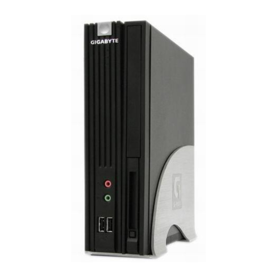
- Page 12 Parts on Panels ■Front Panel MIC Jack Earphone Jack USB Port ■Rear Panel Keyboard (PS2) USB Port VGA Port Serial Port 1 Audio Out Audio In TA Series User’s Manual Power Button Power Indicator LAN Indicator HDD Indicator CD-ROM Door PCMCIA Port PCMCIA Eject Button Mouse (PS2)
- Page 13 1. Please use high quality CDR or CDRW to prevent disks from breaking when running at high speed. 2. Specification of hardware is subject to change without notice. 3. Please visit our site at http://www.gigabyte.com.tw/ to download the latest version of drivers. ■Cautions Improper battery installation may cause explosion.
- Page 14 For use on TA1 series GA-TC2000MB Main Board Specification ■Processor VIA C3 EBGA 733MHz and Above Auto 100/133 MHz FSB Auto Detect CPU Voltage ■Chipset VIA VT8601T (PLE 133T) VIA VT82C686B Chipset with Built-in enhanced Graphics AC97 Audio Codec-Realtek ALC202A LAN Controller-Realtek RTL8100BL ■DRAM 2x168 Pin DIMM Sockets...
- Page 15 ■BIOS 2Mbit Flash RAM AC recovery ON/OFF control Auto detect &report system health status ■Other Features Suspend to RAM(STR) Support Wake-On-LAN(WOL) Front Line-out and Mic Connector Front Panel Connector (Power switch , Power LED , HDD LED , LAN Activity LED and Reset switch) Poly fuse for Keyboard Over-Current Protection TA Series User’s Manual P.
Need help?
Do you have a question about the G-MAX TA1 and is the answer not in the manual?
Questions and answers