Table of Contents
Advertisement
Quick Links
Advertisement
Table of Contents

Subscribe to Our Youtube Channel
Related Manuals for Gigabyte W332-Z00


Summary of Contents for Gigabyte W332-Z00
- Page 1 W332-Z00 AMD Ryzen™ Tower Entry Workstation User Manual Rev. 1.0...
- Page 2 GIGABYTE's prior written permission. Documentation Classifications In order to assist in the use of this product, GIGABYTE provides the following types of documentation: User Manual: detailed information & steps about the installation, configuration and use of this product (e.g.
- Page 3 Conventions The following conventions are used in this user's guide: NOTE! Gives bits and pieces of additional information related to the current topic. CAUTION! Gives precautionary measures to avoid possible hardware or software problems. WARNING! Alerts you to any damage that might result from doing or not doing specific actions.
- Page 4 Warnings and Cautions Before installing, be sure that you understand the following warnings and cautions. WARNING! To reduce the risk of electric shock or damage to the equipment: • Do not disable the power cord grounding plug. The grounding plug is an important safety feature.
- Page 5 Electrostatic Discharge (ESD) CAUTION! ESD CAN DAMAGE DRIVES, BOARDS, AND OTHER PARTS. WE RECOMMEND THAT YOU PERFORM ALL PROCEDURES AT AN ESD WORKSTATION. IF ONE IS NOT AVAILABLE, PROVIDE SOME ESD PROTECTION BY WEARING AN ANTI-STATIC WRIST STRAP AT- TACHED TO CHASSIS GROUND -- ANY UNPAINTED METAL SURFACE -- ON YOUR SERVER WHEN HANDLING PARTS.
- Page 6 CAUTION! Risk of explosion if battery is replaced incorrectly or with an incorrect type. Replace the battery only with the same or equivalent type recommended by the manufacturer. Dispose of used bat- teries according to the manufacturer’s instructions.
- Page 7 GIGABYTE products have not intended to add and safe from hazardous substances (Cd, Pb, Hg, Cr+6, PBDE and PBB). The parts and components have been carefully selected to meet RoHS requirement. More- over, we at GIGABYTE are continuing our efforts to develop products that do not use internationally banned toxic chemicals.
- Page 8 Ra ng 100-240V~,7-3A, 50-60Hz Opera ng Temperature 10°C to 35°C Non-opera ng temperature -40°C to 60°C Opera ng humidity 8%-80% (non-condensing) Non-opera ng humidity 20%-95% (non-condensing) 伺服器相關警告與注意事項 警告 為了避免電擊危險或損壞設備請注意: • 不要切斷電源線的接地端子,接地端子是一個很重要的安全防護。 • 將電源線接到有接地功能的插座,此插座需位於使用者容易使用的範圍。 • 電源線的配線要避免被踩到,被絆到或被過度彎折,重壓。 警告 • 本設備關機後內部仍存在電源,須拔掉電源線才能完全切掉設備內部的電源。 • 更換零件前請確定電源已經完全切斷。 •...
- Page 9 警告 • 如果更換錯誤電池會產生爆炸,請以相同或同型號電池更換使用。 • 廢電池請回收。 注意 • 伺服器開機時不要長時間移除蓋子,長時間移除蓋子會造成散熱功能失效造成損壞。 注意 • 靜電會損害電子產品,建議您在符合靜電防護的工作環境操作伺服器,如果無法確定 環境的靜電防護。請穿上靜電手環並且將手環接到有接地的金屬表面如機櫃或機殼。 • 拿取電路板時僅觸碰板子的邊緣,不要觸碰連接器。板子從防靜電包裝取出後只能放 置在無靜電的桌面,零件面朝上。如果可以, 請使用防靜電泡棉. 避免使用靜電袋. 避免 電路板與任何表面摩擦產生靜電。...
- Page 10 W331-Z00 Equipment name Type designa on (Type) Restricted substances and its chemical symbols Unit 報驗義務人: 技嘉科技股份有限公司 新北市新店區寶強路6號5樓...
-
Page 11: Table Of Contents
Table of Contents Chapter 1 Hardware Installation ...................13 Installation Precautions .................. 13 Product Specifications ..................14 System Block Diagram ................... 17 Chapter 2 System Appearance ..................18 Front View ...................... 18 Rear View ....................... 19 Rear Panel System LAN LEDs ..............20 Chapter 3 System Hardware Installation ..............21 Removing and Installing the Chassis Cover .......... - Page 12 5-2-9 CPU Configuration ....................51 5-2-10 Network Stack Configuration ..................52 5-2-11 CSM Configuration ....................53 5-2-12 Info Report Configuration ..................54 5-2-13 NVMe Configuration ....................55 5-2-14 Offboard SATA Controller Configuration ..............56 5-2-15 SATA Configuration....................57 5-2-16 Realtek PCIe GBE Family Controller ..............58 Chipset Setup Menu ..................59 5-3-1 AMD PSP KVM Configuration ................61 Security Menu ....................
-
Page 13: Chapter 1 Hardware Installation
Chapter 1 Hardware Installation Installation Precautions The motherboard/system contain numerous delicate electronic circuits and components which can become damaged as a result of electrostatic discharge (ESD). Prior to installation, carefully read the user manual and follow these procedures: • Prior to installation, do not remove or break motherboard S/N (Serial Number) sticker or warranty sticker provided by your dealer. -
Page 14: Product Specifications
Product Specifications NOTE: We reserve the right to make any changes to the product specifications and product-related information without prior notice. System Mini-Tower Š 375 x 198 x 370 mm Dimension Š AMD® Ryzen™ 7000 Series Processors Š Chipset AMD® B650E Š... - Page 15 Expansion Slot 1 x PCIe x16 (Gen5 x16) slot; integrated in CPU Š 1 x PCIe x16 (Gen4 x4) slot; integrated in chipset Š 1 x PCIe x1 (Gen4 x1) slot; integrated in chipset Š 2 x M.2 slot for storage: Š...
- Page 16 Power Supply 1 x 500W PSU Š 80 PLUS Bronze Š AC Input: Š - 90-264V; 115V/7A, 230V/3A; 47-63Hz DC Output: Š - Max. 500W +12V/ 41.66A +5V/ 20A +3.3V/ 20A +5Vsb/ 2.5A System Realtek® DASH Remote Management Management Power state settings (on, off, restart, hibernate, or sleep) Š...
-
Page 17: System Block Diagram
System Block Diagram Hardware Installation - 17 -... -
Page 18: Chapter 2 System Appearance
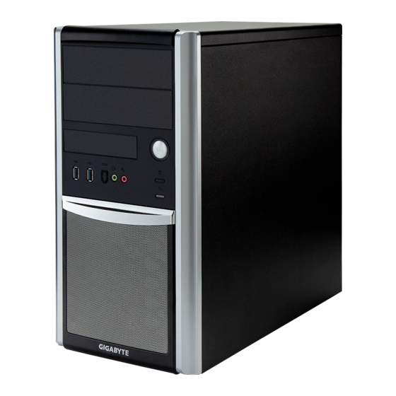
Chapter 2 System Appearance Front View No. Description Description USB 3.2 Ports Power Button The function of 1394 Port is disabled Hard Drives Status LED Line Out Port Reset Button Mic In Port System Appearance - 18 -... -
Page 19: Rear View
Rear View No. Description Description Power Supply Module Cord Socket GbE LAN Port #1 Display Port USB 3.2 Ports Antenna Ports GbE LAN Port #2 HDMI 2.0 Port Line In Port (Blue) USB 3.2 Ports (Type C) Line Out Port (Green) USB 3.2 Ports Mic In Port (Pink) PCIe Card Bay... -
Page 20: Rear Panel System Lan Leds
Rear Panel System LAN LEDs Name Color Status Description Yellow 1 Gbps data rate 1GbE Speed Green 100 Mbps data rate 10 Mbps data rate Link between system and network or no access Green 1GbE Link / Blink Data transmission or reception is occurring. Activity LED No data transmission or reception is occurring. -
Page 21: Chapter 3 System Hardware Installation
Chapter 3 System Hardware Installation Pre-installation Instructions Computer components and electronic circuit boards can be damaged by electrostatic discharge. Working on computers that are still connected to a power supply can be extremely dangerous. Follow the simple guidelines below to avoid damage to your computer or injury to yourself. -
Page 22: Removing And Installing The Chassis Cover
Removing and Installing the Chassis Cover Before you remove or install the chassis cover • Make sure the system is not turned on or connected to AC power. Follow these instructions to remove/install the chassis side cover and front bezel: Remove the screw securing the chassis side cover. -
Page 23: Installing The Cpu
Installing the CPU Read the following guidelines before you begin to install the CPU: • Make sure that the motherboard supports the CPU. • Always turn off the computer and unplug the power cord from the power outlet before installing the CPU to prevent hardware damage. -
Page 24: Installing The Memory
Installing the Memory Read the following guidelines before you begin to install the memory: • Make sure that the motherboard supports the memory. It is recommended that memory of the same capacity, brand, speed, and chips be used. • Always turn off the computer and unplug the power cord from the power outlet before installing the memory to prevent hardware damage. -
Page 25: Installing The Memory
3-3-2 Installing the Memory Before installing a memory module, make sure to turn off the computer and unplug the power cord from the power outlet to prevent damage to the memory module. Be sure to install DDR4 DIMMs on this motherboard. Follow these instructions to install the Memory: Insert the DIMM memory module vertically into the DIMM slot, and push it down. -
Page 26: Installing The Pci Expansion Card
Installing the PCI Expansion Card • Voltages can be present within the server whenever an AC power source is connected. This voltage is present even when the main power switch is in the off position. Ensure that the system is powered-down and all power sources have been disconnected from the server prior to installing a PCIe card. -
Page 27: Installing The Hard Disk Drive
Slide the first hard disk drive into the slot. Mount it with two screws on each side. Slide the second hard disk drive into the dedicated HDD tray. (Note: Connect your GIGABYTE sales representative with any order requests.) Screw the hard disk drive with four screws. -
Page 28: Installing And Removing The M.2 Ssd Module
Installing and Removing the M.2 SSD Module Follow the steps below to install an optional M.2 SSD module on your motherboard. Step1. Insert the M.2 SSD module into the slot. Step2. Secure it with the screw, tightening as necessary to fasten the M.2 SSD module in place. Installing and Removing the M.2 WiFi Module Follow the steps below to install a M.2 WiFi module on your motherboard. -
Page 29: Peripheral Devices Connection
Peripheral Devices Connection System Hardware Installation - 29 -... -
Page 30: Chapter 4 Motherboard Components
Chapter 4 Motherboard Components Motherboard Components DIMM_P0_A0 DIMM_P0_A1 DIMM_P0_B0 DIMM_P0_B1 Motherboard Components - 30 -... - Page 31 Item Description Audio Connectors GbE LAN Port #1 (Top)/USB 3.2 Ports (Bottom) GbE LAN Port #2 USB 3.2 Port Type A(Top)/USB 3.2 Type C Port (Bottom) HDMI 2.0 Port Display Port 2x4 Pin 12V Power Connector CPU Fan Connector System Fan Connector #4 System Fan Connector #2 2x12 Pin Main Power Connector Battery Socket...
-
Page 32: Jumper Setting
Jumper Setting DIMM_P0_A0 DIMM_P0_A1 DIMM_P0_B0 DIMM_P0_B1 Normal Opera on (Default) Clear CMOS CLR_CMOS1 Clear CMOS data Motherboard Components - 32 -... -
Page 33: Chapter 5 Bios Setup
Chapter 5 BIOS Setup BIOS (Basic Input and Output System) records hardware parameters of the system in the EFI on the motherboard. Its major functions include conducting the Power-On Self-Test (POST) during system startup, saving system parameters, loading the operating system etc. The BIOS includes a BIOS Setup program that allows the user to modify basic system configuration settings or to activate certain system features. - Page 34 Main This setup page includes all the items of the standard compatible BIOS. Advanced This setup page includes all the items of AMI BIOS special enhanced features. (ex: Auto detect fan and temperature status, automatically configure hard disk parameters.) ...
-
Page 35: The Main Menu
The Main Menu Once you enter the BIOS Setup program, the Main Menu (as shown below) appears on the screen. Use arrow keys to move among the items and press <Enter> to accept or enter other sub-menu. Main Menu Help The on-screen description of a highlighted setup option is displayed on the bottom line of the Main Menu. - Page 36 Parameter Description BIOS Information Project Name Displays the project name information. BIOS Version Displays version number of the BIOS setup utility. Build Date and Time Displays the date and time when the BIOS setup utility was created. LAN# MAC Address (Note1) Displays LAN MAC address information.
-
Page 37: Advanced Menu
Advanced Menu The Advanced Menu displays submenu options for configuring the function of various hardware components. Select a submenu item, then press <Enter> to access the related submenu screen. BIOS Setup - 37 -... -
Page 38: Dash Configuration
5-2-1 DASH Configuration Parameter Description Desktop and mobile Architecture for System Hardware (DASH) Configuration RTL8111 ID Displays the vendor ID information. RealManage Implementation Guide Displays the utility version. version Enable/Disable RealMange Firmware Control. RealMange Firmware Control (Note) Options available: Enabled, Disabled. Default setting is Disabled. Enable/Disable DASH Support. -
Page 39: Mctp Configuration
5-2-2 MCTP Configuration Parameter Description Management Component Transport Protocol (MCTP) Configuration Enable/Disable MCTP Support. MCTP Support (Note) Options available: Enabled, Disabled. Default setting is Disabled. Enable/Disable PLDM Support for SMBios. PLDM for SMBIOS Options available: Enabled, Disabled. Default setting is Enabled. PLDM for BIOS Control and Enable/Disable PLDM Support for BIOS Control. -
Page 40: Trusted Computing
5-2-3 Trusted Computing Parameter Description Options available: AMD CPU ftPM, Route to SPI TPM. Default AMD fTPM switch setting is Route to SPI TPM. TPM 2.0 Device Found Firmware Version Displays the firmware version information. Vendor Displays the vendor information. Enable/Disable BIOS support for security device. - Page 41 Parameter Description Schedule an operation for the security device. NOTE: Your computer will reboot during restart in order to change Pending operation the state of a security device. Options available: None, TPM Clear. Default setting is None. Enable/Disable platform hierarchy. Platform Hierarchy Options available: Enabled, Disabled.
-
Page 42: Asf Configuration
5-2-4 ASF Configuration Description Parameter Alert Standard Format (ASF) Configuration Options available: OFF, On, Alert Only. Default setting is On. ASF BIOS Mode Enable/Disable WatchDog Timer. ASF WatchDog Timer Options available: Enabled, Disabled. Default setting is Disabled. BIOS Setup - 42 -... -
Page 43: Super Io Configuration
5-2-5 Super IO Configuration Description Parameter Super IO Configuration Super IO Chip Displays the super IO chip information Serial Port 1 Press [Enter] for configuration of advanced items. Configuration BIOS Setup - 43 -... - Page 44 5-2-5-1 Serial Port 1 Configuration Description Parameter Serial Port 1 Configuration Enable/Disable the Serial Port (COM). When set to Enabled allows you to configure the Serial port 1 settings. When set to Disabled, displays no Serial Port (Note1) configuration for the serial port. Options available: Enabled, Disabled.
-
Page 45: Hardware Monitor
5-2-6 Hardware Monitor Parameter Description CPU FAN Fail Warning Options available: Enabled, Disabled. Default setting is Enabled. SYS FAN1/2/3 Fail Options available: Enabled, Disabled. Default setting is Disabled. Warning Options available: Full Speed, Standard Mode. Default setting is Standard CPU FAN Speed Control Mode. -
Page 46: S5 Rtc Wake Settings
5-2-7 S5 RTC Wake Settings Parameter Description Enable/Disable system wake on alarm event. Options available: Disabled, Fixed Time. When Fixed Time is selected, Wake System from S5 system will wake on the hr::min::sec specified. Default setting is Disabled. BIOS Setup - 46 -... -
Page 47: Serial Port Console Redirection
5-2-8 Serial Port Console Redirection Parameter Description Select whether to enable console redirection for specified device. Console COM Console redirection enables the users to manage the system from a remote Redirection (Note) location. Options available: Enabled, Disabled. Default setting is Disabled. Press [Enter] to configure advanced items. - Page 48 Parameter Description Parity Š – A parity bit can be sent with the data bits to detect some transmission errors. – Even: parity bit is 0 if the num of 1's in the data bits is even. – Odd: parity bit is 0 if num of 1's in the data bits is odd. –...
- Page 49 Parameter Description Legacy Console Redirection Press [Enter] to configure advanced items. Redirection COM Port Š – Selects a COM port for Legacy serial redirection. Resolution Š – Selects the number of rows and columns used in Console Redirection for legacy OS support. Legacy Console Redirection –...
- Page 50 Parameter Description Flow Control EMS Š – Flow control can prevent data loss from buffer overflow. When sending data, if the receiving buffers are full, a 'stop' signal can Serial Port for Out-of-Band be sent to stop the data flow. Once the buffers are empty, a 'start' EMS Console Redirection signal can be sent to re-start the flow.
-
Page 51: Cpu Configuration
5-2-9 CPU Configuration Description Parameter CPU Configuration Displays the module version information. Module Version Displays the AGESA version information. AGESA Version Enable/Disable the generation of ACPI_PPC, _PSS, and _PCT objects. PSS Support Options available: Enabled, Disabled. Default setting is Enabled. Options available: PState 0, PState 1, PState 2. -
Page 52: Network Stack Configuration
5-2-10 Network Stack Configuration Parameter Description Enable/Disable the UEFI network stack. Network Stack Options available: Enabled, Disabled. Default setting is Disabled. Enable/Disable the Ipv4 PXE feature. Ipv4 PXE Support (Note) Options available: Enabled, Disabled. Default setting is Enabled. Enable/Disable the Ipv4 HTTP feature. Ipv4 HTTP Support (Note) Options available: Enabled, Disabled. -
Page 53: Csm Configuration
5-2-11 CSM Configuration Parameter Description Compatibility Support Module Configuration Enable/Disable CSM support. CSM Support (Note) Options available: Enabled, Disabled. Default setting is Disabled. CSM16 Module Version Displays the module version information. Options available: Upon Request, Always. Default setting is Upon GateA20 Active Request. -
Page 54: Info Report Configuration
5-2-12 Info Report Configuration Parameter Description Info Report Configuration Enable/Disable Post Report support. Post Report (Note) Options available: Enabled, Disabled. Default setting is Disabled. Sets the POST Report wait time. Delay Time Options available: 0, 1, 2, 3, 4, 5, 6, 7, 8, 9, 10, Until Press ESC. Default setting is 5. -
Page 55: Nvme Configuration
5-2-13 NVMe Configuration Parameter Description NVMe Configuration Displays the NVMe devices connected to the system. BIOS Setup - 55 -... -
Page 56: Offboard Sata Controller Configuration
5-2-14 Offboard SATA Controller Configuration Parameter Description Offboard SATA Controller Displays the information on your PCIe SATA controllers/ PCIe SSD if Configuration installed. BIOS Setup - 56 -... -
Page 57: Sata Configuration
5-2-15 SATA Configuration Parameter Description Displays the installed HDD devices information. System will automatically SATA Configuration detect HDD type. BIOS Setup - 57 -... -
Page 58: Realtek Pcie Gbe Family Controller
5-2-16 Realtek PCIe GBE Family Controller Description Parameter Realtek PCIe GBE Family Press [Enter] to view the Network Interface Controller information. Controller BIOS Setup - 58 -... -
Page 59: Chipset Setup Menu
Chipset Setup Menu Chipset Setup menu displays submenu options for configuring the function of the onboard controller. Parameter Description Integrated Graphics Enable/Disable Integrated Graphics controller. Controller Options available: Disabled, Forces, Auto. Default setting is Forces. Options available: Auto, 64M, 128M, 256M, 512M. Default setting is Auto. UMA Frame buffer Size Options available: Int Graphics (IFD), Ext Graphics (PEG). - Page 60 Parameter Description NVMe RAID Mode Options available: AHCI, RAID. Default setting is AHCI. Changes CPU performance mode. CPU Performance Options available: Standard Mode, Performance Mode. Default setting is Standard Mode. AMD PSP KVM Configuration Press [Enter] to configure advanced items. BIOS Setup - 60 -...
-
Page 61: Amd Psp Kvm Configuration
5-3-1 AMD PSP KVM Configuration Parameter Description AMD PSP KVM Configuration AMD PSP KVM feature Enable/Disable AMD PSP KVM feature. Options available: Disabled, Enabled, Clear. Default setting is Disabled. Enable (Note) Resolution select for AMD PSP Options available: 1280 x 1024, 1024 x 768. Default setting is 1024 x 768. -
Page 62: Security Menu
Security Menu The Security menu allows you to safeguard and protect the system from unauthorized use by setting up access passwords. There are two types of passwords that you can set: • Administrator Password Entering this password will allow the user to access and change all settings in the Setup Utility. •... -
Page 63: Secure Boot
5-4-1 Secure Boot The Secure Boot submenu is applicable when your device is installed the Windows 8 (or above) operating ® system. Parameter Description System Mode Displays if the system is in User mode or Setup mode. Enable/ Disable the Secure Boot function. Secure Boot Options available: Enabled, Disabled. - Page 64 Parameter Description Press [Enter] to configure advanced items. Please note that this item is configurable when Secure Boot Mode is set to Custom. Factory Key Provision Š – Allows to provision factory default Secure Boot keys when system is in Setup Mode.
-
Page 65: Boot Menu
Boot Menu The Boot menu allows you to set the drive priority during system boot-up. BIOS setup will display an error message if the legacy drive(s) specified is not bootable. Parameter Description Boot Configuration Number of seconds to wait for setup activation key. 65535 (0xFFFF) Setup Prompt Timeout means indefinite waiting. -
Page 66: Save & Exit Menu
Save & Exit Menu The Save & Exit menu displays the various options to quit from the BIOS setup. Highlight any of the exit options then press <Enter>. Parameter Description Save Options Saves changes made and closes the BIOS setup. Save Changes and Reset Options available: Yes, No. -
Page 67: Bios Post Beep Code (Ami Standard)
BIOS POST Beep code (AMI standard) 5-7-1 PEI Beep Codes # of Beeps Description Memory not Installed. Memory was installed twice (InstallPeiMemory routine in PEI Core called twice) Recovery started DXEIPL was not found DXE Core Firmware Volume was not found Recovery failed S3 Resume failed Reset PPI is not available...
Need help?
Do you have a question about the W332-Z00 and is the answer not in the manual?
Questions and answers