
Related Manuals for Rockwell Automation RELIANCE ELECTRIC INVERTRON DBU-50


Summary of Contents for Rockwell Automation RELIANCE ELECTRIC INVERTRON DBU-50
- Page 1 INVERTRON DBU Dynamic Braking Unit Instruction Manual Manual P/N. 899.05.26 User Manual: 49‘1328e (06) Publication INVDBU-UM006F-EN-P...
-
Page 3: Table Of Contents
TABLE OF CONTENTS 1. DESCRIPTION 1-1...1-2 Operation ........................1-1 Line voltage selection ....................1-2 Parameter setting on the inverter................... 1-2 Permissible loading of the electronics ................1-2 2. SPECIFICATIONS 2-1...2-4 Electrical specification of the Braking Unit ..............2-1 Ambient conditions......................2-1 Mechanical specification, dimensions ................ - Page 4 GENERAL NOTES Safety Instructions DANGER, WARNING, and CAUTION point out potential trouble areas. A DANGER alerts a person that high voltage is present which could result in severe bodily injury or loss of life. A WARNING alerts a person to potential bodily injury if procedures are not followed. A CAUTION alerts a person that, if procedures are not followed, damage to, or destruction of equipment could result.
-
Page 5: Description 1-1
DESCRIPTION Operation Frequency converters (Inverters) with DC bus and input diode rectifier bridge are suitable for the operation of three phase AC-motors in two drive quadrants, motoring in both directions of rotation. Braking with more than 10% of the rated inverter current is only possible with a braking unit. Without a braking unit, an excessively rapid deceleration causes an increase in the DC bus voltage. -
Page 6: Line Voltage Selection
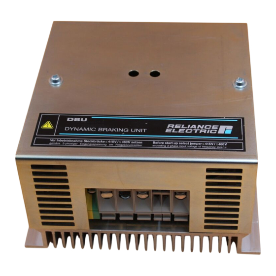
DESCRIPTION Line Voltage Selection After removing the cover plate of the DBU the blue jumper plug with positions 460V / 415V is accessible at the upper edge of the regulator card (middle on BUC, right on BUA). This jumper plug defines the DC bus voltage at which the DBU switches the DB resistor to the DC bus. When delivered from stock the DBU is adjusted for safety reasons to 460 V line voltage. -
Page 7: Specifications 2-1
SPECIFICATIONS Electrical Specification Table 2-1: Power Ratings DBU-50 DBU-100 DBU-200 DBU-400 Maximum braking current Imax 50 A 100 A 200 A 400 A* Minimum braking resistor permitted for max. braking power: with 415V jumper 12.8 ohms 6.4 ohms 3.2 ohms 1.6 ohms 14.4 ohms 7.2 ohms 3.6 ohms... -
Page 8: Mechanical Specification, Dimensions
SPECIFICATIONS Mechanical Specification, Dimensions ø6.5 121.5 Weight: 3.1 kg Figure 2-1: Dimensions and fixing holes for the Braking Units DBU-50 and DBU-100 29 101 PE 47 47 45 0/115/ 29/101 Type Weight: Power connections Control connections DBU-200 9 kg Terminal block below 1) Terminal block below below without DBU-400... -
Page 9: Optional Diagnostic Card Bud
SPECIFICATIONS Optional diagnostic card BUD The diagnostic card BUD, (part No. 813.02.00) is incorporated on units DBU-xx-DIS and all DBU-400. On units DBU-xx (with PWM-regulator BUC) the diagnostic card option set DBU-DIS (Part No. 839.25.41) can be built in on site or used as a replacement part. On DBU-400 units the BUD card is always built-in as a standard. - Page 10 SPECIFICATIONS Analog output A Signal A at terminals 5 and 6 is depending on the power P dissipated in the DB resistor. The analog signal is generated through a filter circuit from the modulated voltage across the DB- resistor. The indication range 0% to 100% pulse width (on BUC) respectively duty ratio (on BUA) corresponds with 0 - 20 mA.
-
Page 11: Mounting And Connection 3-1
MOUNTING AND CONNECTION Mounting of the Braking Unit For free air circulation through the cooling fins of the power section, the braking unit must be screwed onto a vertical panel according to figures 2-1 or 2-2. To prevent overheating due to heat build-up, minimum clearances for air circulation of 100 mm above and below the unit must be observed. - Page 12 MOUNTING AND CONNECTION Power Connections Refer also to the installation instructions according EMC regulations in Appendix A. 1. Connection leads between Inverter and DBU During switching of the braking units IGBT the inductance of the lead between the DC bus capacitors of the Inverter and the DBU generates short time (some µs) overvoltage peaks.
-
Page 13: Connection
MOUNTING AND CONNECTION 2. Connection leads between DBU and DB resistor R Because of the many different types of DB resistor constructions the inductance differs in a wide range. High inductance (e.g. wire wound on ceramic core) at low resistance can limit the permitted lead length especially for DBU-200 and -400. -
Page 15: Design Information 4-1
DESIGN INFORMATION Calculation of braking power Calculation of the braking power P at linear braking rate t • ∆ • [kW] • 91200 tB [kg m : moment of inertia of the drive systems, relative to the motor shaft [min : speed before the braking process ∆n [min... -
Page 16: Example
DESIGN INFORMATION Example Roller table with 20 motors: Each motor: 2.5 kW, 4.5 A, 460 V - 60 Hz 120 operations/h Braking time: 1.8s Braking torque = nominal torque 150% Overload capability required: 90 x 1.5 = 135 A → GV3000 AC140 Total power: 20 x 2.5 kW = 50 kW / AC 90 A = 10 Ω... -
Page 17: Emc Directive
A - CE CONFORMITY EMC Directive This device is a component intended for implementation in machines or systems for the capital goods industry. The units have been tested to meet Council Directive 89/336 Electromagnetic Compatibility (EMC) and all applicable standards (listed in the technical construction file). With the measures as described in this guidelines the DBU can be operated CE-conform according to product standard EN 61800-3 or generic standards EN 50081-2, EN 50082-2 as follows: Emission limits:... -
Page 18: Wiring Instruction
A - CE CONFORMITY Wiring Instruction General • All the leads of a cable connection shall have the same cross section. (earth conductors with cross section >16 : min. 16 or 50% of phase lead) • The connections between Inverter and DBU should be as short as possible!! •... - Page 19 A - CE CONFORMITY Configuration Cabinet Panel Braking resistor Inverter 45, 47 RFI-Filter U,V,W L1- L3 AC-Input line reactor AC-Input contactor AC-Input fuses Terminals for 4-wire AC-input cable (L1,L2,L3, PE) Cabinet protection ground busbar ➀ Cable bracket ➁ Shield ➂ Shielded 4-wire motor cable ➃...
-
Page 20: Installation Of Standalone Drives
A - CE CONFORMITY Installation of Standalone Drives in IP20 Enclosure L1, L2, L3 INVERTER R, S, T (L1, L2, L3) FILTER 45,47 45,47 47,48 U,V,W L1', L2', L3' U,V,W ➀ AC-Line input ➂ Screened 4-wire motor cable ➃ Screened signal conductor cable(feedback, reference) ➄... - Page 22 Reach us now at www.rockwellautomation.com Wherever you need us, Rockwell Automation brings together leading brands in industrial automation including Allen-Bradley controls, Reliance Electric power transmission products, Dodge mechanical power transmission components, and Rockwell Software. Rockwell Automation's unique, flexible approach to helping customers achieve a competitive advantage is supported by thousands of authorized partners, distributors and system integrators around the world.
Need help?
Do you have a question about the RELIANCE ELECTRIC INVERTRON DBU-50 and is the answer not in the manual?
Questions and answers