Table of Contents
Advertisement
Quick Links
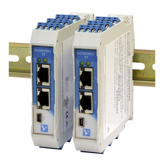
BusWorks® XT Series
10/100MB Industrial Ethernet I/O Modules
USB Programmable, Profinet I/O
Model XT1543-000
Combination Analog Voltage Output and Digital I/O
(8 DC Voltage Output Channels and 4 Digital I/O Channels w/
Active-High Inputs and Tandem High-Side Switched Outputs)
USER'S MANUAL
ACROMAG INCORPORATED
Tel: (248) 295-0880
30765 South Wixom Road
Fax: (248) 624-9234
Wixom, MI 48393-2417 U.S.A.
email: sales@acromag.com
Copyright 2014, Acromag, Inc., Printed in the USA.
8501-017B
Data and specifications are subject to change without notice.
Advertisement
Table of Contents

Subscribe to Our Youtube Channel
Related Manuals for Acromag BusWorks XT1543-000


Summary of Contents for Acromag BusWorks XT1543-000
- Page 1 Active-High Inputs and Tandem High-Side Switched Outputs) USER’S MANUAL ACROMAG INCORPORATED Tel: (248) 295-0880 30765 South Wixom Road Fax: (248) 624-9234 Wixom, MI 48393-2417 U.S.A. email: sales@acromag.com Copyright 2014, Acromag, Inc., Printed in the USA. 8501-017B Data and specifications are subject to change without notice.
-
Page 2: Table Of Contents
Network Home Page ......................26 BLOCK DIAGRAM ..................... 27 How It Works ........................27 About Profinet IO ......................28 Profinet GSDML File ......................29 Profinet Mapping Table ..................... 30 Acromag, Inc. Tel: 248-295-0880 - 2 - - 2 - http://www.acromag.com http://www.acromag.com... - Page 3 This is very important where property loss or human life is involved. It is important that you perform satisfactory overall system design and it is agreed between you and Acromag, that this is your responsibility.
-
Page 4: Getting Started
USB connection to any Windows-based PC (Windows XP and later versions only) running model- specific configuration software. Network communication parameters are setup over the network using a Profinet Configuration tool. Acromag, Inc. Tel: 248-295-0880 - 4 - - 4 - http://www.acromag.com... -
Page 5: Mechanical Dimensions
Above 55°C, a space of at least 20mm between modules is recommended to aide cooling in this manner. Acromag, Inc. Tel: 248-295-0880 - 5 - - 5 - http://www.acromag.com... -
Page 6: Electrical Connections
As a rule, output wires are normally separated from power and network wiring for safety and isolation, as well as for low noise. Acromag, Inc. Tel: 248-295-0880 - 6 - - 6 - http://www.acromag.com... -
Page 7: Power Connections
TO THE UNIT MAY RESULT. NOTE: IT IS RECOMMENDED THAT SUPPLIES CAPABLE OF DELIVERING MORE THAN 2.5A TO THE BUS BE FUSED WITH A HIGH SURGE TOLERANT FUSE. Acromag, Inc. Tel: 248-295-0880 - 7 - - 7 - http://www.acromag.com http://www.acromag.com... -
Page 8: Usb Connection
USB connection to configure the unit. USB Signal Isolation Recommended - You may use Acromag model USB- ISOLATOR to isolate your USB port, or you can optionally use another USB signal isolator that supports USB Full Speed operation (12Mbps). USB isolation is required to break the inadvertent ground loop between the output circuits and earth ground at your PC. -
Page 9: Output Connections
Observe proper polarity when making digital output excitation connections. Refer to the following figures to wire the voltage outputs, digital outputs, and digital output excitation of this model. Acromag, Inc. Tel: 248-295-0880 - 9 - - 9 - http://www.acromag.com... - Page 10 DC current through the load to output return (RTN). Outputs share a common return connection and are not isolated channel- to-channel. Refer to the following figures for example DC Voltage Output connections to this model. Acromag, Inc. Tel: 248-295-0880 - 10 - - 10 - http://www.acromag.com...
- Page 11 Per UL, when the outputs are used to drive interposing relays for switching AC or DC devices of higher voltage/current, the coil ratings for the interposing relay shall not exceed 24VDC, 100mA. Acromag, Inc. Tel: 248-295-0880 - 11 - - 11 - http://www.acromag.com...
-
Page 12: Digital Input Connections
NOTE: You do not need to connect digital excitation if you are only using the digital input channel to monitor a field input (tandem output is OFF). Digital excitation is only required to operate the sourcing digital output channel. Acromag, Inc. Tel: 248-295-0880 - 12 - - 12 - http://www.acromag.com... -
Page 13: Emi Filter Installation
28A2029-0A2 or similar for inputs/outputs and Power (order Acromag 4001-135), Laird 28A0592-0A2 or similar for USB cable (Acromag 4001-140), and Laird 28A0807592-0A2 or similar for Ethernet cable (Acromag 4001-139). Locate ferrites by clamping them outside of all I/O cables or wiring harnesses to/from the module (USB, Ethernet, input/output group, DC power), and as close to the module as possible. -
Page 14: Earth Ground Connections
USB port and this makes contact with both the USB signal and shield ground which is held in common to the input circuit return of this module. Acromag, Inc. Tel: 248-295-0880 - 14 - - 14 - http://www.acromag.com... -
Page 15: Configuration Software
This zip file will extract to a modelconfig.exe executable file installed in an Acromag subdirectory off the Program Files directory of your PC. Note that you must have administrator rights to download and install this software onto your PC or laptop. - Page 16 Use [Zero] and [Full Scale] and measure the Configuration Step-by-Step section of Technical Reference on output range zero or full-scale signal and enter page 17 of this manual. the measured value here. Acromag, Inc. Tel: 248-295-0880 - 16 - - 16 - http://www.acromag.com http://www.acromag.com...
-
Page 17: Technical Reference
Its I/O is configured by initially connecting to USB with a host PC running model-specific configuration software. As a Profinet I/O module, its network communication parameters are configured online using a Profinet configuration tool. Acromag, Inc. Tel: 248-295-0880 - 17 - - 17 - http://www.acromag.com... -
Page 18: Device/Communication Setup
Note that you should already have power connected to the XT1543 at this point, as this model does not utilize USB power. After executing the Acromag Configuration software for this model, a screen similar to that shown below will appear, if you have not already connected to your transmitter via USB (note Device Select fields are blank under these conditions). - Page 19 Static addressing is as the name implies—static, and represents a unique fixed IP Address generally assigned by your service provider or system administrator. The default address assigned to this module is 192.168.1.100 and static (refer to product side label). Acromag, Inc. Tel: 248-295-0880 - 19 - - 19 - http://www.acromag.com...
- Page 20 You can click the [Exit] button in the lower right hand part of this screen to exit the Configuration Software, or simply click on another tab to access another page before exiting this software. Acromag, Inc. Tel: 248-295-0880 - 20 - - 20 - http://www.acromag.com...
-
Page 21: I/O Config/Test Page
This is also useful to reset an output that may be in a latched thermal shutdown following overload conditions. Acromag, Inc. Tel: 248-295-0880 - 21 - - 21 - http://www.acromag.com... - Page 22 Be sure to first stop polling before moving onto another page. Status: This field displays status messages relative to sending and receiving channel I/O over USB to the module. Acromag, Inc. Tel: 248-295-0880 - 22 - - 22 - http://www.acromag.com...
- Page 23 HELP – You can press [F1] for Help on a selected or highlighted field or control. You can also click the [?] button in the upper-right hand corner of the screen and click to point to a field or control to get a Help message pertaining to the item you pointed to. Acromag, Inc. Tel: 248-295-0880 - 23 - - 23 - http://www.acromag.com...
-
Page 24: Calibration Page
The DAC count that produced this value will be stored and associated with this range level. The zero and full- scale DAC counts determined here are used to develop a linear relationship between the output voltage and the DAC. Acromag, Inc. Tel: 248-295-0880 - 24 - - 24 - http://www.acromag.com... - Page 25 Calibration of all outputs is further streamlined by doing all output channel zero endpoints first, followed by doing all the channel full-scale endpoints next, each in succession. Acromag, Inc. Tel: 248-295-0880 - 25 - - 25 - http://www.acromag.com...
-
Page 26: Network Home Page
USB connection to the device (scroll down this page to view all applicable parameter settings). Acromag, Inc. Tel: 248-295-0880 - 26 - - 26 - http://www.acromag.com... -
Page 27: Block Diagram
IP address of your network card to match the module’s subnet address domain. Refer to the block diagram above to gain a better understanding of how this model works. Acromag, Inc. Tel: 248-295-0880 - 27 - - 27 - http://www.acromag.com... -
Page 28: About Profinet Io
You can get the GSDML file for this model from the CDROM shipped with your unit, or you may download it from our web site at www.acromag.com, or from the Profinet web site at www.profibus.com. Acromag, Inc. Tel: 248-295-0880... -
Page 29: Profinet Gsdml File
It is a combinational acronym taken from its language XML (eXtensible Markup Language) and its function GSD (General Station Description). For this device, the file is GSDML-V2.30-Acromag-XT1543-xxxxxxxx.xml, where xxxxxxxx = YYYYMMDD of the revision (YearMonthDay). V2.30 deals with the version of the GSDML schematic that the file was based on. -
Page 30: Profinet Mapping Table
±5V or ±10V output range OUTPUT AO Channel 7 Unsigned 16-bit Output CH7 normalized count (Consumed) of ±30000, or ±20000 with Legacy support, representing ±5V or ±10V output range Acromag, Inc. Tel: 248-295-0880 - 30 - - 30 - http://www.acromag.com http://www.acromag.com... -
Page 31: Troubleshooting
Return module to Acromag for Acromag’s Application Engineers repair/reprogramming. can provide further technical Unit Fails to Start-up or Initialize…... - Page 32 USB Software Fails to Detect Module… Bad USB Connection Recheck USB Cable Connection USB has not enumerated the Use the reset button of the Acromag USB device. isolator to trigger renumeration of the module, or simply unplug and replug the USB cable to the module.
- Page 33 Most 12V supplies are ±10%. This unit does voltage below 11.5V. not operate below 11.5V. Check your actual supply voltage under load and make sure it is at least 11.5V. Acromag, Inc. Tel: 248-295-0880 - 33 - - 33 - http://www.acromag.com http://www.acromag.com...
-
Page 34: Service & Repair Assistance
Acromag for repair or replacement. Acromag has automated test equipment that thoroughly checks and calibrates the performance of each module, and can restore firmware. Please refer to Acromag’s Service Policy and Warranty Bulletins, or contact Acromag for complete details on how to obtain repair or replacement. -
Page 35: Accessories
ST, TT, or XT module. It is normally included in XT-SIP. Note that software for all XT Series models is available free of charge, online at www.acromag.com. Acromag, Inc. Tel: 248-295-0880 - 35 - - 35 - http://www.acromag.com... -
Page 36: Din Rail Bus Connector Kit
Ethernet Patch Cable, 3 feet long, Model 5035-369 Ethernet Patch Cable, 15 feet long, Model 5035-370 This cable is used to connect a module to your network switch (like an Acromag 900EN-S005 or equivalent Ethernet switch), and is double-shielded for potentially lower emissions and increased RFI resistance. -
Page 37: Specifications
SPECIFICATIONS Model Number XT1543-000 (Eight Voltage Output The XT1543-000 is a member of the Acromag DIN-Rail mounted, “Busworks” family Channels combined w/ Four of network I/O modules in the XT Series. The XT1543-000 model provides eight Sourcing Digital I/O Channels) channels of DC Voltage Output, plus four sourcing digital I/O channels. - Page 38 Analog Output Cable Length: Output interface cables should not exceed 30m in length for rated performance. Reference Test Conditions: ±10V output into 10KΩ; ambient temperature = 25 C; 24VDC supply. Acromag, Inc. Tel: 248-295-0880 - 38 - - 38 - http://www.acromag.com...
-
Page 39: Digital Outputs & Excitation
Note: Per UL, when the outputs are used to control interposing relays for switching AC and DC devices of higher voltage/current, the coil ratings for the interposing relay shall not exceed 24VDC, 100mA. Acromag, Inc. Tel: 248-295-0880 - 39 - - 39 - http://www.acromag.com... -
Page 40: Digital Inputs
1.7VDC, typical, High-to-Low threshold is 1.6VDC, typical. Logic limits are TTL with 0.8VDC Max LOW level, and 2.0VDC Min HIGH level. Input Resistance: 10K, typical (inputs include 10KΩ pull-downs to return). Acromag, Inc. Tel: 248-295-0880 - 40 - - 40 - http://www.acromag.com... -
Page 41: Power
USB shield and signal ground, and this will drive ground loop setup and configured in a safe errors when your I/O is also grounded. environment only. Acromag, Inc. Tel: 248-295-0880 - 41 - - 41 - http://www.acromag.com... -
Page 42: Ethernet Interface
IP address in the address domain of the module. Refer to Acromag Application Note 8500-734 for example instructions on how to change the IP address of your PC network interface card in order to talk to an Acromag module. Acromag, Inc. Tel: 248-295-0880... -
Page 43: Enclosure & Physical
This is a Class A Product with Emissions per BS EN 61000-6-4: 1) Enclosure Port, per CISPR 16. 2) Low Voltage AC Mains Port, per CISPR 16. Telecom / Network Port, per CISPR 22. Acromag, Inc. Tel: 248-295-0880 - 43 - - 43 - http://www.acromag.com... -
Page 44: Agency Approvals
The following table shows the revision history for this document: Release Date Version EGR/DOC Description of Revision 26-AUG-14 BC/ARP Updated Initial Release. 13-OCT-14 BC/ARP Added UL approvals (removed pending) per 14K010, added MTBF data. Acromag, Inc. Tel: 248-295-0880 - 44 - - 44 - http://www.acromag.com http://www.acromag.com...
Need help?
Do you have a question about the BusWorks XT1543-000 and is the answer not in the manual?
Questions and answers