Table of Contents
Advertisement
Quick Links
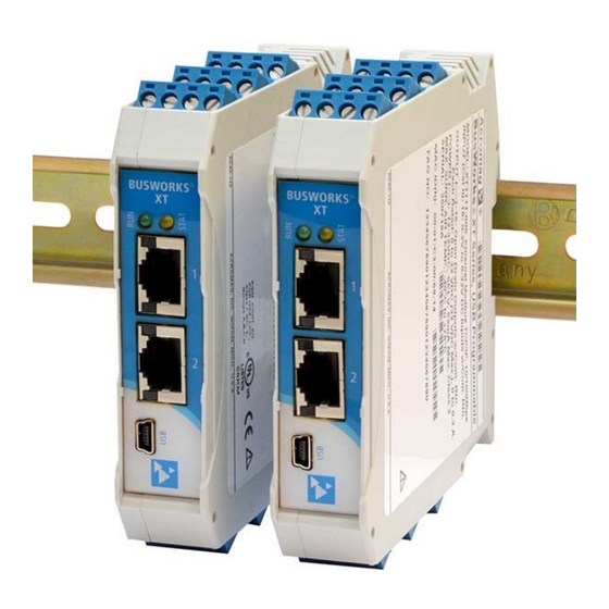
BusWorks® XT Series
10/100MB Industrial Ethernet I/O Modules
USB Programmable, Modbus TCP/IP I/O
Model XT1531‐000
Combination Analog Current Output and Digital I/O
(4 DC Current Outputs and 4 Digital Inputs w/
4 Tandem High‐Side Switch Outputs)
USER'S MANUAL
ACROMAG INCORPORATED
Tel: (248) 295‐0880
30765 South Wixom Road
email: sales@acromag.com
Wixom, MI 48393‐2417 U.S.A.
Copyright 2015, Acromag, Inc., Printed in the USA.
8501012H
Data and specifications are subject to change without notice.
Advertisement
Table of Contents

Subscribe to Our Youtube Channel
Related Manuals for Acromag BusWorks XT1531-000


Summary of Contents for Acromag BusWorks XT1531-000
- Page 1 4 Tandem High‐Side Switch Outputs) USER’S MANUAL ACROMAG INCORPORATED Tel: (248) 295‐0880 30765 South Wixom Road email: sales@acromag.com Wixom, MI 48393‐2417 U.S.A. Copyright 2015, Acromag, Inc., Printed in the USA. 8501012H Data and specifications are subject to change without notice.
-
Page 2: Table Of Contents
IP Addressing ........................33 Dynamic Host Configuration Protocol (DHCP) ..............34 Domain Name System (DNS) ....................35 MODBUS REGISTERS ..................35 Register Functions ......................36 Data Types ......................... 37 Register Map ........................37 Acromag, Inc. Tel: 248‐295‐0880 ‐ 2 ‐ https://www.acromag.com... - Page 3 This is very important where property loss or human life is involved. It is important that you perform satisfactory overall system design and it is agreed between you and Acromag, that this is your responsibility.
-
Page 4: Getting Started
10/100Mbps Ethernet interface using the Modbus TCP/IP application protocol. Units are conveniently setup and configured for network operation via a USB connection to a host computer running Acromag configuration software. This model includes support for i2o at its digital inputs and also acts as an i2o target Acromag, Inc. -
Page 5: Mechanical Dimensions
DC– ground, you should remove this clip to prevent a second connection to ground via the DIN rail, which could generate a ground loop. Connecting to one earth ground via the screw terminals on the unit is recommended for best performance. Acromag, Inc. Tel: 248‐295‐0880 ‐ 5 ‐ https://www.acromag.com... -
Page 6: Electrical Connections
I/O wiring, adequate wire insulation should be used and proper wiring practices followed. As a rule, output wires are normally separated from power and network wiring for safety and isolation, as well as for low noise. Acromag, Inc. Tel: 248‐295‐0880 ‐ 6 ‐ https://www.acromag.com... -
Page 7: Power Connections
For supply connections, use 14 AWG wire rated for at least 80°C. Do not exceed 36V DC peak. Note that output channels of this model will require separate connections to power (see Output Connections). Acromag, Inc. Tel: 248‐295‐0880 ‐ 7 ‐ https://www.acromag.com... -
Page 8: Usb Connection
Important – End Stops: If this module uses the optionally powered (or redundantly powered) via the DIN rail bus for hazardous location installations (Class I, Division 2 or ATEX Zone 2) it must use two end stops (Acromag 1027‐222) to secure the terminal block and module (not shown). - Page 9 4 CH Current Output + 4 CH Digital I/O w/USB & Modbus BusWorks Model XT1531‐000 Acromag, Inc. Tel: 248‐295‐0880 ‐ 9 ‐ https://www.acromag.com...
-
Page 10: Output Connections
12V analog excitation terminals, or damage to the 12V TVS diode and voltage regulator will result. Refer to the following figures to wire the current outputs, digital outputs, and excitation of these models. Acromag, Inc. Tel: 248‐295‐0880 ‐ 10 ‐ https://www.acromag.com... - Page 11 WARNING: In order to operate current outputs, you must additionally provide 12V or 24V excitation to the appropriate analog Excitation terminals as shown above. DO NOT CONNECT 24V EXCITATION TO THE 12V TERMINALS, OR DAMAGE Acromag, Inc. Tel: 248‐295‐0880 ‐ 11 ‐...
- Page 12 BusWorks Model XT1531‐000 WILL RESULT. You can optionally use the second analog excitation terminals to connect redundant backup excitation if required, but you must observe the proper voltage level for the particular terminal. Acromag, Inc. Tel: 248‐295‐0880 ‐ 12 ‐ https://www.acromag.com...
- Page 13 Per UL, when the outputs are used to drive interposing relays for switching AC or DC devices of higher voltage/current, the coil ratings for the interposing relay shall not exceed 24VDC, 100mA. Acromag, Inc. Tel: 248‐295‐0880 ‐ 13 ‐ https://www.acromag.com...
-
Page 14: Digital Input Connections
NOTE: You do not need to connect digital excitation if you are only using the digital input channels to monitor field inputs. Digital excitation is only required to operate the tandem sourcing digital outputs. Acromag, Inc. Tel: 248‐295‐0880 ‐ 14 ‐ https://www.acromag.com... -
Page 15: Emi Filter Installation
28A2029‐0A2 or similar for inputs/outputs and Power (order Acromag 4001‐135), Laird 28A0592‐0A2 or similar for USB cable (Acromag 4001‐140), and Laird 28A0807592‐0A2 or similar for Ethernet cable (Acromag 4001‐139). Locate ferrites by clamping them outside of all I/O cables or wiring harnesses to/from the module (USB, Ethernet, input/output group, DC power), and as close to the module as possible. -
Page 16: Earth Ground Connections
Initially, you will have to answer a few questions to open a user account and download this file to your computer. This zip file will extract to a modelconfig.exe executable file installed in an Acromag subdirectory off the Program Files directory of your PC. Note that you must have administrator rights to download and install this software onto your PC or laptop. -
Page 17: Quick Overview
I/O Config/Test Page (Configure Your Unit Here) powered up. After connecting to your unit and setting up its network parameters, click the I/O Config/Test Page tab to display the screen at left. Acromag, Inc. Tel: 248‐295‐0880 ‐ 17 ‐ https://www.acromag.com... - Page 18 Turn digital outputs On/Off with [Channel…]. • Use [Start/Stop Polling] to poll digital inputs. • Display the current state of the inputs with simulated LED’s and “1” or “0” superimposed on the lamps for ON or OFF. Acromag, Inc. Tel: 248‐295‐0880 ‐ 18 ‐ https://www.acromag.com...
- Page 19 For a more detailed configuration procedure, see the configuration to the connected module. Configuration Step‐by‐Step section of the Technical Reference on page 18 of this manual. Acromag, Inc. Tel: 248‐295‐0880 ‐ 19 ‐ https://www.acromag.com...
-
Page 20: Configuration Step-By-Step
IP address setting, or having to change the address setting of your network card to match the module’s subnet address domain in order to talk to it. Acromag, Inc. Tel: 248‐295‐0880 ‐ 20 ‐ https://www.acromag.com... -
Page 21: Device/Communication Setup
USB power and you will not be able to configure, calibrate, or test the unit without power & excitation applied. After executing the Acromag Configuration software for this model, a screen similar to that shown below will appear, if you have not already connected to your transmitter via USB (note Device Select fields are blank under these conditions). - Page 22 IP addresses. The DNS 1 Address refers to the IP address of the first Domain Name Server used on this network. The DNS 2 Address refers to the IP address of the secondary Domain Name Server used on this network. Acromag, Inc. Tel: 248‐295‐0880 ‐ 22 ‐...
- Page 23 You can click the [Exit] button in the lower right hand part of this screen to exit the Configuration Software, or simply click on another tab to access another page before exiting this software. Acromag, Inc. Tel: 248‐295‐0880 ‐ 23 ‐...
-
Page 24: I/O Config/Test Page
Output Auto‐Refresh: You can specify that outputs should be rewritten periodically to ensure they maintain their programmed state following a digital upset, perhaps by some extraordinary transient event. This is also useful to reset an output that may be in a latched thermal shutdown following overload conditions. Acromag, Inc. Tel: 248‐295‐0880 ‐ 24 ‐ https://www.acromag.com... - Page 25 [Channel…] Button: Click this button to turn the associated output ON. Note that turning it ON connects the output to the digital excitation source (high‐side switch). A “1” is superimposed on the lamp for ON, and “0” for OFF (true regardless of the Invert Input logic Setting). Acromag, Inc. Tel: 248‐295‐0880 ‐ 25 ‐ https://www.acromag.com...
- Page 26 HELP – You can press [F1] for Help on a selected or highlighted field or control. You can also click the [?] button in the upper‐right hand corner of the screen and click to point to a field or control to get a Help message pertaining to the item you pointed to. Acromag, Inc. Tel: 248‐295‐0880 ‐ 26 ‐ https://www.acromag.com...
-
Page 27: Calibration Page
The DAC count that produced this value will then be stored and associated with this range level. The zero and full‐scale DAC counts determined here are used to develop a linear relationship between the output current and DAC. Acromag, Inc. Tel: 248‐295‐0880 ‐ 27 ‐ https://www.acromag.com... - Page 28 Calibration of all outputs is further streamlined by doing all output channel zero endpoints first, then doing all the channel full‐scale endpoints, each in succession. Acromag, Inc. Tel: 248‐295‐0880 ‐ 28 ‐ https://www.acromag.com...
-
Page 29: I2O Mapping Page
IMPORTANT: i2o refers to an Acromag proprietary method of input‐to‐output communication, done over the network, without other hard‐wired connections between inputs and outputs. This is not a Modbus TCP/IP function and the i2o mapping feature of this model may only be configured via this software. - Page 30 T > 99sec Disabled Enabled Invalid Configuration w/ a long time over an open socket. This will work but it is not recommended to keep the socket open for infrequent i2o updates. Acromag, Inc. Tel: 248‐295‐0880 ‐ 30 ‐ https://www.acromag.com...
- Page 31 Mapping… The four input channels of this device may be mapped to four output channels at another Acromag digital I/O module at one or two different IP addresses. Subsequent messages will be sent at a periodic rate specified by update time. Note that the target output channels may still be controlled independently via the network, but their state will be overwritten by subsequent mapped messages when enabled.
-
Page 32: Network Home Page
USB connection to the device (scroll down this page to view all applicable parameter settings). Acromag, Inc. Tel: 248‐295‐0880 ‐ 32 ‐... -
Page 33: Block Diagram
IP address of your network card to match the module’s subnet address domain. Refer to the block diagram above to gain a better understanding of how this model works. Acromag, Inc. Tel: 248‐295‐0880 ‐ 33 ‐ https://www.acromag.com... -
Page 34: About Modbus Tcp/Ip
(Ethernet), with a networking standard (TCP/IP), and a standard method of representing data (Modbus). Then, a Modbus TCP/IP message is simply a Modbus communication encapsulated in an Ethernet TCP/IP wrapper. Acromag, Inc. Tel: 248‐295‐0880 ‐ 34 ‐ https://www.acromag.com... -
Page 35: Ip Addressing
TIP: The first node (0), node 10, and the last node (255 for our example) are typically reserved for servers and may yield poor results if used. Acromag, Inc. Tel: 248‐295‐0880 ‐ 35 ‐ https://www.acromag.com... -
Page 36: Dynamic Host Configuration Protocol (Dhcp)
Only static IP addresses will ensure a connection every time, while dynamic addresses do not. Acromag, Inc. Tel: 248‐295‐0880 ‐ 36 ‐ https://www.acromag.com... -
Page 37: Domain Name System (Dns)
IP addresses. These servers contain information on some segment of the domain name space and make this information available to clients called resolvers. For example, the DNS allows us to use “Acromag.com” as an IP address rather than a more complicated number string. -
Page 38: Register Functions
03 (Illegal Data Value) will be returned in the response. Refer to the Modbus spec for a complete list of possible error codes. Note that register mirroring, used in some earlier Acromag models, is not supported by Series XT models. -
Page 39: Data Types
The “Support Coil versus Holding Register for Digital Output Writes” option is a global setting that applies to all digital outputs of a module. It is enabled or disabled from the Analog Output/Digital I/O Configuration page of the USB Configuration Software for this model. Acromag, Inc. Tel: 248‐295‐0880 ‐ 39 ‐ https://www.acromag.com... - Page 40 0. This logic only excitation will have to be cycled switches (signal is applies if the Input Logic Invert OFF/ON to restore output active‐high). function is set to “No” or disabled. operation. Acromag, Inc. Tel: 248‐295‐0880 ‐ 40 ‐ https://www.acromag.com...
- Page 41 Set AO CH 01 Value 16‐bit Signed Integer Output Value 40004 3 (0003) Set AO CH 02 Value 16‐bit Signed Integer Output Value 40005 4 (0004) Set AO CH 03 Value 16‐bit Signed Integer Output Value Acromag, Inc. Tel: 248‐295‐0880 ‐ 41 ‐ https://www.acromag.com...
- Page 42 // saving time when writing their own code to control the XT1111 or XT1121 // modules from Acromag. As such, Acromag Inc. shall not be held liable for // any direct, indirect or consequential damages with respect to any claims // arising from the content of such software and/or the use made by customers // of the coding information contained herein in connection with their products.
- Page 43 OutputWord[ channel / 4 ] |= 0x0004; else OutputWord[ channel / 4 ] &= ~0x0004; break; case 3: case 7: case 11: case 15: if( state ) OutputWord[ channel / 4 ] |= 0x0008; else Acromag, Inc. Tel: 248‐295‐0880 ‐ 43 ‐ https://www.acromag.com...
- Page 44 4 CH Current Output + 4 CH Digital I/O w/USB & Modbus BusWorks Model XT1531‐000 OutputWord[ channel / 4 ] &= ~0x0008; Acromag, Inc. Tel: 248‐295‐0880 ‐ 44 ‐ https://www.acromag.com...
- Page 45 // set/clear the outputs as needed WriteDigitalOutput(1, ON); WriteDigitalOutput(12, OFF); // write the outputs using whatever Modbus hook you have, this is an example and yours will differ for(Loop=0; Loop<4; Loop++) WriteHoldingRegister(FIRST_DO_HADDRESS + Loop, OutputWord[Loop]); Acromag, Inc. Tel: 248‐295‐0880 ‐ 45 ‐ https://www.acromag.com...
-
Page 46: Troubleshooting
Return module to Acromag for Acromag’s Application Engineers repair/reprogramming. can provide further technical Unit Fails to Start‐up or Initialize…... - Page 47 USB Software Fails to Detect Module… Bad USB Connection Recheck USB Cable Connection USB has not enumerated the Use the reset button of the Acromag USB device. isolator to trigger renumeration of the module, or simply unplug and replug the USB cable to the module.
- Page 48 ON/OFF state in your output write to keep it ON/OFF). Optionally, you can select support coil register control versus holding register control (unless the output is an i2o target which always uses holding register control). Acromag, Inc. Tel: 248‐295‐0880 ‐ 48 ‐ https://www.acromag.com...
- Page 49 In this case, connect 24V mistake. excitation (20‐28V) to the 24V terminals to continue operation. If not having 12V analog excitation is inconvenient, then you may return your unit to Acromag for repair. Acromag, Inc. Tel: 248‐295‐0880 ‐ 49 ‐ https://www.acromag.com...
-
Page 50: Service & Repair Assistance
Acromag for repair or replacement. Acromag has automated test equipment that thoroughly checks and calibrates the performance of each module, and can restore firmware. Please refer to Acromag’s Service Policy and Warranty Bulletins, or contact Acromag for complete details on how to obtain repair or replacement. -
Page 51: Accessories
This is a 1 meter, USB A‐miniB replacement cable for connection between the USB isolator and any ST, TT, or XT module. It is normally included in XT‐SIP. Note that software for all XT Series models is available free of charge, online at https://www.acromag.com. Accessories… Acromag, Inc. Tel: 248‐295‐0880 ‐ 51 ‐ https://www.acromag.com... -
Page 52: Din Rail Bus Connector Kit
Ethernet Patch Cable, 3 feet long, Model 5035‐369 Ethernet Patch Cable, 15 feet long, Model 5035‐370 This cable is used to connect a module to your network switch (like an Acromag 900EN‐S005 or equivalent Ethernet switch), and is double‐shielded for lower emissions and increased RFI resistance. -
Page 53: Specifications
SPECIFICATIONS Model Number XT1531‐000 (Four Current Output The XT1531‐000 is a member of the Acromag DIN‐Rail mounted, “Busworks” family Channels combined w/ Four of network I/O modules in the XT Series. The XT1531‐000 model provides four Sourcing Digital I/O Channels) channels of DC current output, plus four sourcing digital I/O channels. - Page 54 ADS5362BSTZ, operating in bipolar mode with a 2.76267V reference, yielding a 16‐bit D/A output voltage range of ±5.52534V corresponding to a raw DAC count of ‐32768 to +32767 and a normalized program count of ±30000. Acromag, Inc. Tel: 248‐295‐0880 ‐ 54 ‐ https://www.acromag.com...
-
Page 55: Digital Outputs
Note: Per UL, when the outputs are used to control interposing relays for switching AC and DC devices of higher voltage/current, the coil ratings for the interposing relay shall not exceed 24VDC, 100mA. Acromag, Inc. Tel: 248‐295‐0880 ‐ 55 ‐ https://www.acromag.com... -
Page 56: Digital Inputs
Digital Input Transient Voltage Suppressor: Installed at every I/O point, the rated working voltage is 38V, breakdown voltage is 47V, and clamping level is 72V. Acromag, Inc. Tel: 248‐295‐0880 ‐ 56 ‐ https://www.acromag.com... -
Page 57: Power
Note: Most Host Personal Computers (except battery powered laptops) will connect earth ground to the USB shield and signal ground, and this will drive ground loop errors when your I/O is also grounded. Acromag, Inc. Tel: 248‐295‐0880 ‐ 57 ‐ https://www.acromag.com... -
Page 58: Ethernet Interface
Address: The module’s IP address can be preset (static) by the user via USB. At startup, it can be loaded from internal non‐volatile memory, or it can be automatically acquired via a network server using DHCP (Dynamic Host Configuration Protocol). Acromag, Inc. Tel: 248‐295‐0880 ‐ 58 ‐ https://www.acromag.com... -
Page 59: Enclosure & Physical
This is a Class A Product with Emissions per BS EN 61000‐6‐4: 1) Enclosure Port, per CISPR 16. 2) Low Voltage AC Mains Port, per CISPR 16. Telecom / Network Port, per CISPR 22. Acromag, Inc. Tel: 248‐295‐0880 ‐ 59 ‐ https://www.acromag.com... -
Page 60: Agency Approvals
LED Indicators: RUN (Green) – Located at front panel. Constant ON if power is on and unit is OK. Flashes ON/OFF during initialization, or if flashing continuously, it may indicate a firmware issue. Acromag, Inc. Tel: 248‐295‐0880 ‐ 60 ‐ https://www.acromag.com... -
Page 61: Revision History
13 NOV 2017 FJM/ARP Reference Configuration Software without the revision. 03 MAY 2019 FJM/ARP Update Slave ID. Updated EN IEC Standards. Changed ATEX protection 18 NOV 2022 CAP/AMM method from “nA” to “ec”. Acromag, Inc. Tel: 248‐295‐0880 ‐ 61 ‐ https://www.acromag.com...
Need help?
Do you have a question about the BusWorks XT1531-000 and is the answer not in the manual?
Questions and answers