Table of Contents
Advertisement
Quick Links
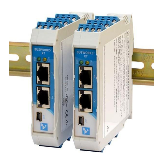
BusWorks® XT Series
10/100MB Industrial Ethernet I/O Modules
USB Programmable, Ethernet/IP I/O
Model XT1532‐000
Combination Analog Current Output and Digital I/O
(4 DC Current Outputs and 4 Digital Inputs w/
4 Tandem High‐Side Switch Outputs)
USER'S MANUAL
ACROMAG INCORPORATED
Tel: (248) 295‐0880
30765 South Wixom Road
Fax: (248) 624‐9234
Wixom, MI 48393‐2417 U.S.A.
email: sales@acromag.com
Copyright 2015, Acromag, Inc., Printed in the USA.
8501013F
Data and specifications are subject to change without notice.
Advertisement
Table of Contents

Related Manuals for Acromag XT1532-000


Summary of Contents for Acromag XT1532-000
- Page 1 4 Tandem High‐Side Switch Outputs) USER’S MANUAL ACROMAG INCORPORATED Tel: (248) 295‐0880 30765 South Wixom Road Fax: (248) 624‐9234 Wixom, MI 48393‐2417 U.S.A. email: sales@acromag.com Copyright 2015, Acromag, Inc., Printed in the USA. 8501013F Data and specifications are subject to change without notice.
-
Page 2: Table Of Contents
Object Models ........................29 Assembly Object ........................31 EDS File (Electronic Data Sheet) ................... 32 IP Addressing ........................33 Dynamic Host Configuration Protocol (DHCP) ..............34 Domain Name System (DNS) ....................34 Acromag, Inc. Tel: 248‐295‐0880 ‐ 2 ‐ http://www.acromag.com... - Page 3 This is very important where property loss or human life is involved. It is important that you perform satisfactory overall system design and it is agreed between you and Acromag, that this is your responsibility.
-
Page 4: Getting Started
10/100Mbps Ethernet interface using an Ethernet/IP application protocol. Units are conveniently setup and configured for network operation via a USB connection to a host computer running Acromag configuration software. Acromag, Inc. Tel: 248‐295‐0880 ‐ 4 ‐... -
Page 5: Mechanical Dimensions
DIN rail, allowing cool air to enter in through the bottom vents and warm air to exhaust out the top vents. Above 50°C, a space of at least 20mm between modules should be maintained to aide cooling in this manner. Acromag, Inc. Tel: 248‐295‐0880 ‐ 5 ‐ http://www.acromag.com... -
Page 6: Electrical Connections
I/O wiring, adequate wire insulation should be used and proper wiring practices followed. As a rule, output wires are normally separated from power and network wiring for safety and isolation, as well as for low noise. Acromag, Inc. Tel: 248‐295‐0880 ‐ 6 ‐ http://www.acromag.com... -
Page 7: Power Connections
CAUTION: DO NOT EXCEED 36VDC, OR DAMAGE TO THE UNIT MAY RESULT. NOTE: IT IS RECOMMENDED THAT SUPPLIES CAPABLE OF DELIVERING MORE THAN 2.5A TO THE BUS BE FUSED WITH A HIGH SURGE TOLERANT FUSE. Acromag, Inc. Tel: 248‐295‐0880 ‐ 7 ‐ http://www.acromag.com... -
Page 8: Usb Connection
Important – End Stops: If this module uses the optionally powered (or redundantly powered) via the DIN rail bus for hazardous location installations (Class I, Division 2 or ATEX Zone 2) it must use two end stops (Acromag 1027‐222) to secure the terminal block and module (not shown). -
Page 9: Output Connections
12V analog excitation terminals, or damage to the 12V TVS diode and voltage regulator will result. Refer to the following figures to wire the current outputs, digital outputs, and excitation of these models. Acromag, Inc. Tel: 248‐295‐0880 ‐ 9 ‐ http://www.acromag.com... - Page 10 Excitation terminals as shown above. DO NOT CONNECT 24V EXCITATION TO THE 12V TERMINALS, OR DAMAGE WILL RESULT. You can optionally use the second analog excitation terminals to connect redundant backup excitation if required, but you must observe the proper voltage level for the particular terminal. Acromag, Inc. Tel: 248‐295‐0880 ‐ 10 ‐ http://www.acromag.com...
- Page 11 Per UL, when the outputs are used to drive interposing relays for switching AC or DC devices of higher voltage/current, the coil ratings for the interposing relay shall not exceed 24VDC, 100mA. Acromag, Inc. Tel: 248‐295‐0880 ‐ 11 ‐ http://www.acromag.com...
-
Page 12: Digital Input Connections
NOTE: You do not need to connect digital excitation if you are only using the digital input channels to monitor field inputs. Digital excitation is only required to operate the tandem sourcing digital outputs. Acromag, Inc. Tel: 248‐295‐0880 ‐ 12 ‐ http://www.acromag.com... -
Page 13: Emi Filter Installation
28A2029‐0A2 or similar for inputs/outputs and Power (order Acromag 4001‐135), Laird 28A0592‐0A2 or similar for USB cable (Acromag 4001‐140), and Laird 28A0807592‐0A2 or similar for Ethernet cable (Acromag 4001‐139). Locate ferrites by clamping them outside of all I/O cables or wiring harnesses to/from the module (USB, Ethernet, input/output group, DC power), and as close to the module as possible. -
Page 14: Earth Ground Connections
Initially, you will have to answer a few questions to open a user account and download this file to your computer. This zip file will extract to a modelconfig.exe executable file installed in an Acromag subdirectory off the Program Files directory of your PC. -
Page 15: Quick Overview
After connecting to your unit and setting up its network parameters, click the I/O Config/Test Page tab to display the screen at left. Acromag, Inc. Tel: 248‐295‐0880 ‐ 15 ‐ http://www.acromag.com... - Page 16 Turn digital outputs On/Off with [Channel…]. • Use [Start/Stop Polling] to poll digital inputs. • Display the current state of the inputs with simulated LED’s and “1” or “0” superimposed on the lamps for ON or OFF. Acromag, Inc. Tel: 248‐295‐0880 ‐ 16 ‐ http://www.acromag.com...
- Page 17 For a more detailed configuration procedure, see the Configuration Step‐by‐Step section of the Technical Reference on page 18 of this manual. Acromag, Inc. Tel: 248‐295‐0880 ‐ 17 ‐ http://www.acromag.com...
-
Page 18: Technical Reference
IP address setting, or having to change the address setting of your network card to match the module’s subnet address domain in order to talk to it. Acromag, Inc. Tel: 248‐295‐0880 ‐ 18 ‐ http://www.acromag.com... -
Page 19: Device/Communication Setup
USB power and you will not be able to configure, calibrate, or test the unit without power & excitation applied. After executing the Acromag Configuration software for this model, a screen similar to that shown below will appear, if you have not already connected to your transmitter via USB (note Device Select fields are blank under these conditions). - Page 20 IP addresses. The DNS 1 Address refers to the IP address of the first Domain Name Server used on this network. The DNS 2 Address refers to the IP address of the secondary Domain Name Server used on this network. Acromag, Inc. Tel: 248‐295‐0880 ‐ 20 ‐...
- Page 21 You can click the [Exit] button in the lower right hand part of this screen to exit the Configuration Software, or simply click on another tab to access another page before exiting this software. Acromag, Inc. Tel: 248‐295‐0880 ‐ 21 ‐...
-
Page 22: I/O Config/Test Page
Output Auto‐Refresh: You can specify that outputs should be rewritten periodically to ensure they maintain their programmed state following a digital upset, perhaps by some extraordinary transient event. This is also useful to reset an output that may be in a latched thermal shutdown following overload conditions. Acromag, Inc. Tel: 248‐295‐0880 ‐ 22 ‐ http://www.acromag.com... - Page 23 Be sure to first stop polling before moving onto another page. Status: This field displays status messages relative to sending and receiving channel I/O over USB to the module. Acromag, Inc. Tel: 248‐295‐0880 ‐ 23 ‐...
- Page 24 HELP – You can press [F1] for Help on a selected or highlighted field or control. You can also click the [?] button in the upper‐right hand corner of the screen and click to point to a field or control to get a Help message pertaining to the item you pointed to. Acromag, Inc. Tel: 248‐295‐0880 ‐ 24 ‐ http://www.acromag.com...
-
Page 25: Calibration Page
The DAC count that produced this value will then be stored and associated with this range level. The zero and full‐scale DAC counts determined here are used to develop a linear relationship between the output current and DAC. Acromag, Inc. Tel: 248‐295‐0880 ‐ 25 ‐ http://www.acromag.com... - Page 26 Thus, calibration of all outputs is streamlined by doing all output channel zero endpoints first, then doing all the channel full‐scale endpoints, each in succession. Acromag, Inc. Tel: 248‐295‐0880 ‐ 26 ‐ http://www.acromag.com...
-
Page 27: Network Home Page
USB connection to the device (scroll down this page to view all applicable parameter settings). Acromag, Inc. Tel: 248‐295‐0880 ‐ 27 ‐... -
Page 28: Block Diagram
IP address of your network card to match the module’s subnet address domain. Refer to the block diagram above to gain a better understanding of how this model works. Acromag, Inc. Tel: 248‐295‐0880 ‐ 28 ‐ http://www.acromag.com... -
Page 29: About Ethernet/Ip
EtherNet/IP™”, 8500‐747. This document is included on the CDROM that is bundled with the XT‐SIP configuration kit (purchased separately) and may also be downloaded from our web site at www.acromag.com. You may also obtain a copy of the EtherNet/IP™ standard from the Open deviceNet Vendor association (ODVA) web site for EtherNet/IP™... - Page 30 Details for the Assembly Object are included below, because this object is needed to establish a connection. Details for the remaining objects will not be included here, as these details can be obtained by module query once a connection has been established. Acromag, Inc. Tel: 248‐295‐0880 ‐ 30 ‐ http://www.acromag.com...
-
Page 31: Assembly Object
0 specifies the input is OFF or in its high state (high > 2.0V). This assumes integer value with a range of 0‐ the Invert Input Logic function is set to “No” or disabled. 65535. Acromag, Inc. Tel: 248‐295‐0880 ‐ 31 ‐ http://www.acromag.com... -
Page 32: Eds File (Electronic Data Sheet)
Acromag_XT1532.eds and it is included on the CDROM of the XT‐SIP kit (purchased separately). You can open the EDS file with any ASCII Text Editor if you wish to examine its contents. Acromag, Inc. Tel: 248‐295‐0880 ‐ 32 ‐ http://www.acromag.com... -
Page 33: Ip Addressing
IP address belongs to by performing a bitwise AND operation between the mask itself, and the IP address, with the result being the sub‐network address, and the remaining bits the host or node address. Acromag, Inc. Tel: 248‐295‐0880 ‐ 33 ‐ http://www.acromag.com... -
Page 34: Dynamic Host Configuration Protocol (Dhcp)
IP addresses. These servers contain information on some segment of the domain name space and make this information available to clients called resolvers. For example, the DNS allows us to use “Acromag.com” as an IP address rather than a more complicated number string. -
Page 35: Troubleshooting
Return module to Acromag for Acromag’s Application Engineers repair/reprogramming. can provide further technical Unit Fails to Start‐up or Initialize…... - Page 36 USB Software Fails to Detect Module… Bad USB Connection Recheck USB Cable Connection USB has not enumerated the Use the reset button of the Acromag USB device. isolator to trigger renumeration of the module, or simply unplug and replug the USB cable to the module.
- Page 37 (i.e. if an adjacent channel is currently ON or OFF, you need to reinforce the ON/OFF state in your output write to keep it ON/OFF). Acromag, Inc. Tel: 248‐295‐0880 ‐ 37 ‐ http://www.acromag.com...
- Page 38 (20‐28V) to the 24V terminals to continue operation. If not having 12V analog excitation is inconvenient, then you may return your unit to Acromag for repair. Network Status Field of Device Setup Page Indicates “Failed” Error… A connection to the unit’s...
-
Page 39: Service & Repair Assistance
Acromag for repair or replacement. Acromag has automated test equipment that thoroughly checks and calibrates the performance of each module, and can restore firmware. Please refer to Acromag’s Service Policy and Warranty Bulletins, or contact Acromag for complete details on how to obtain repair or replacement. -
Page 40: Usb A-Mini B Cable
Ethernet Patch Cable, 3 feet long, Model 5035‐369 Ethernet Patch Cable, 15 feet long, Model 5035‐370 This cable is used to connect a module to your network switch (like an Acromag 900EN‐S005 or equivalent Ethernet switch), and is double‐shielded for lower emissions and increased RFI resistance. -
Page 41: Specifications
4 CH Current Output + 4 CH Digital I/O w/USB & Ethernet/IP™ SPECIFICATIONS Model Number The XT1532‐000 is a member of the Acromag DIN‐Rail mounted, “Busworks” family XT1532‐000 (Four Current Output Channels combined w/ Four of network I/O modules in the XT Series. The XT1532‐000 model provides four Sourcing Digital I/O Channels) channels of DC current output, plus four sourcing digital I/O channels. - Page 42 ADS5362BSTZ, operating in bipolar mode with a 2.76267V reference, yielding a 16‐bit D/A output voltage range of ±5.52534V corresponding to a raw DAC count of ‐32768 to +32767 and a normalized program count of ±30000. Acromag, Inc. Tel: 248‐295‐0880 ‐ 42 ‐ http://www.acromag.com...
-
Page 43: Digital Outputs
Note: Per UL, when the outputs are used to control interposing relays for switching AC and DC devices of higher voltage/current, the coil ratings for the interposing relay shall not exceed 24VDC, 100mA. Acromag, Inc. Tel: 248‐295‐0880 ‐ 43 ‐ http://www.acromag.com... -
Page 44: Digital Inputs
Digital Input Transient Voltage Suppressor: Installed at every I/O point, the rated working voltage is 38V, breakdown voltage is 47V, and clamping level is 72V. Acromag, Inc. Tel: 248‐295‐0880 ‐ 44 ‐ http://www.acromag.com... -
Page 45: Power
Note: Most Host Personal Computers (except battery powered laptops) will connect earth ground to the USB shield and signal ground, and this will drive ground loop errors when your I/O is also grounded. Acromag, Inc. Tel: 248‐295‐0880 ‐ 45 ‐ http://www.acromag.com... -
Page 46: Ethernet Interface
IP address in the address domain of the module. Refer to Acromag Application Note 8500‐734 for example instructions on how to change the IP address of your PC network interface card in order to talk to an Acromag module. Acromag, Inc. Tel: 248‐295‐0880 ‐... -
Page 47: Enclosure & Physical
This is a Class A Product with Emissions per BS EN 61000‐6‐4: 1) Enclosure Port, per CISPR 16. 2) Low Voltage AC Mains Port, per CISPR 16. Telecom / Network Port, per CISPR 22. Acromag, Inc. Tel: 248‐295‐0880 ‐ 47 ‐ http://www.acromag.com... -
Page 48: Agency Approvals
LED Indicators: RUN (Green) – Located at front panel. Constant ON if power is on and unit is OK. Flashes ON/OFF during initialization, or if flashing continuously, it may indicate a firmware issue. Acromag, Inc. Tel: 248‐295‐0880 ‐ 48 ‐ http://www.acromag.com... -
Page 49: Revision History
Shows terminals 11 and 12 with the incorrect polarity. 15‐OCT‐2015 CAP/ARP Added ATEX symbols / statements. 22‐AUG‐2016 CAP/MJO Corrected “Circuit Board” specification. 14 NOV 2017 FJM/ARP Reference Configuration Software without the revision. Acromag, Inc. Tel: 248‐295‐0880 ‐ 49 ‐ http://www.acromag.com...
Need help?
Do you have a question about the XT1532-000 and is the answer not in the manual?
Questions and answers