Table of Contents
Advertisement
Quick Links
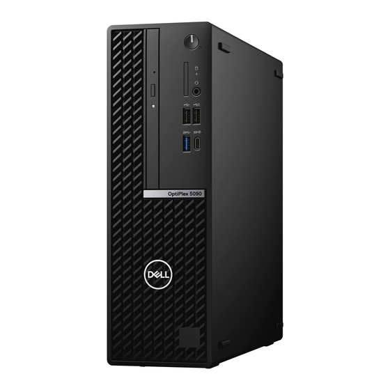
OptiPlex 5090 Small Form Factor
Service Manual
Regulatory Model: D15S
Regulatory Type: D15S004
April 2021
Rev. A00
Questo manuale d'istruzione è fornito da trovaprezzi.it. Scopri tutte le offerte per
SFF i5-10505 / 16GB / 256GB / Windows 10 Pro
Desktop e Workstation
o cerca il tuo prodotto tra le
Dell OptiPlex 5090
migliori offerte di PC
Advertisement
Table of Contents

Related Manuals for Dell OptiPlex 5090 Small Form Factor


Summary of Contents for Dell OptiPlex 5090 Small Form Factor
- Page 1 Dell OptiPlex 5090 SFF i5-10505 / 16GB / 256GB / Windows 10 Pro o cerca il tuo prodotto tra le migliori offerte di PC Desktop e Workstation OptiPlex 5090 Small Form Factor Service Manual Regulatory Model: D15S Regulatory Type: D15S004 April 2021...
- Page 2 A WARNING indicates a potential for property damage, personal injury, or death. © 2021 Dell Inc. or its subsidiaries. All rights reserved. Dell, EMC, and other trademarks are trademarks of Dell Inc. or its subsidiaries. Other trademarks may be trademarks of their respective owners.
-
Page 3: Table Of Contents
Contents Chapter 1: Working inside your computer..................6 Safety instructions................................6 Before working inside your computer........................6 Safety precautions.................................7 Electrostatic discharge—ESD protection........................7 ESD field service kit ..............................8 Transporting sensitive components.......................... 9 After working inside your computer..........................9 Chapter 2: Removing and installing components................10 Recommended tools................................10 Screw List.................................... - Page 4 Removing the fan and heat-sink assembly......................38 Installing the fan and heat-sink assembly......................38 Graphics card..................................39 Removing the graphics card............................. 39 Installing the graphics card............................40 Coin-cell battery.................................41 Removing the coin-cell battery..........................41 Installing the coin-cell battery..........................42 Memory modules................................43 Removing the memory modules..........................43 Installing the memory modules..........................
- Page 5 Assigning a system setup password........................85 Deleting or changing an existing system setup password.................86 Chapter 5: Troubleshooting......................87 Dell SupportAssist Pre-boot System Performance Check diagnostics..............87 Running the SupportAssist Pre-Boot System Performance Check..............87 System diagnostic lights..............................87 Real-Time Clock (RTC Reset)............................89 Flashing the BIOS................................89...
-
Page 6: Chapter 1: Working Inside Your Computer
You should only perform troubleshooting and repairs as authorized or directed by the Dell technical assistance team. Damage due to servicing that is not authorized by Dell is not covered by your warranty. See the safety instructions that is shipped with the product or at www.dell.com/regulatory_compliance. -
Page 7: Safety Precautions
ESD protection is an increasing concern. Due to the increased density of semiconductors used in recent Dell products, the sensitivity to static damage is now higher than in previous Dell products. For this reason, some previously approved methods of handling parts are no longer applicable. -
Page 8: Esd Field Service Kit
It is recommended that all field service technicians use the traditional wired ESD grounding wrist strap and protective anti-static mat at all times when servicing Dell products. In addition, it is critical that technicians keep sensitive parts separate from all insulator parts while performing service and that they use anti-static bags for transporting sensitive components. -
Page 9: Transporting Sensitive Components
Transporting sensitive components When transporting ESD sensitive components such as replacement parts or parts to be returned to Dell, it is critical to place these parts in anti-static bags for safe transport. After working inside your computer About this task CAUTION: Leaving stray or loose screws inside your computer may severely damage your computer. -
Page 10: Chapter 2: Removing And Installing Components
Removing and installing components NOTE: The images in this document may differ from your computer depending on the configuration you ordered. Recommended tools The procedures in this document may require the following tools: ● Phillips #0 screwdriver ● Phillips #1 screwdriver ●... -
Page 11: Major Components Of Your System
Major components of your system 1. Side cover Removing and installing components... -
Page 12: Side Cover
17. M.2 WLAN 18. Speaker NOTE: Dell provides a list of components and their part numbers for the original system configuration purchased. These parts are available according to warranty coverages purchased by the customer. Contact your Dell sales representative for purchase options. - Page 13 Steps 1. Slide the release latch to the right until your hear a click and slide the cover towards the back of the computer. 2. Lift the side cover from the computer. Removing and installing components...
-
Page 14: Installing The Side Cover
Installing the side cover Prerequisites If you are replacing a component, remove the existing component before performing the installation procedure. About this task The following image shows the side cover and provides a visual representation of the installation procedure. Removing and installing components... -
Page 15: Intrusion Switch
Steps 1. Place the side cover onto the system aligning the tabs on the chassis. 2. Slide the side cover towards the front of the computer until you hear the release latch click. Next steps 1. Follow the procedure in after working inside your computer. -
Page 16: Front Bezel
About this task The following image indicates the location of the intrusion switch and provides a visual representation of the installation procedure. Steps 1. Slide the intrusion switch into the slot on the chassis. 2. Insert the connector from intrusion switch cable into the connector on the system board until it clicks into place. Next steps 1. -
Page 17: Installing The Front Bezel
Steps 1. Gently pry and release the front-cover tabs sequentially from the top. 2. Rotate the front cover outward from the chassis. 3. Remove the front bezel from the chassis. Installing the front bezel Prerequisites If you are replacing a component, remove the existing component before performing the installation procedure. About this task The following image indicates the location of the front bezel and provides a visual representation of the installation procedure. - Page 18 Removing and installing components...
-
Page 19: Hard Drive
Steps 1. Align and insert the front-cover tabs with the slots on the chassis. 2. Rotate the front cover towards the chassis and snap it into place. Next steps 1. Install the side cover. 2. Follow the procedure in after working inside your computer. -
Page 20: Removing The 2.5-Inch Hard-Drive
Steps 1. Disconnect the hard-drive data and power cables from the connectors on the hard drive and push the left tab towards the hard-drive to free the caddy from the chassis 2. Release the hard-drive caddy from the tabs on the right side and slide the hard-drive caddy out. NOTE: The hard-drive's power and data cables can only connected from the bottom side of the caddy. -
Page 21: Installing The 2.5/3.5-Inch Hard-Drive Caddy
Steps 1. Pull the two tabs from the hard-drive caddy away from the hard-drive. 2. Slide the hard-drive towards the right to free it from the mounting points on the caddy and lift it away from the system. Installing the 2.5/3.5-inch hard-drive caddy Prerequisites If you are replacing a component, remove the existing component before performing the installation procedure. -
Page 22: Installing The 2.5-Inch Hard-Drive
Steps 1. Place the tabs on the right side of the hard-drive caddy onto the holders on the chassis and push the left side of the caddy down until it clicks into place. NOTE: Use the arrows seen on the caddy as guides to identify the tabs on the tray. 2. -
Page 23: Solid-State Drive
Steps 1. Align the hard-drive with the mounting points on the caddy and place the hard-drive onto it. 2. Pull the tabs on the right side of the caddy until the hard-drive clicks into place. Next steps 1. Install the 2.5/3.5-inch hard-drive caddy. -
Page 24: Installing The M.2 2230 Solid-State Drive
Steps 1. Remove the single (M2x3) screw that secures the solid-state drive to the system board. 2. Slide and lift the solid-state drive off the system board. Installing the M.2 2230 solid-state drive Prerequisites If you are replacing a component, remove the existing component before performing the installation procedure. About this task The following image indicates the location of the M.2 2230 solid-state drive and provides a visual representation of the installation procedure. -
Page 25: Removing The M.2 2280 Solid-State Drive
Steps 1. Align the solid-state drive with the socket on the system board and slide it in. 2. Replace the single (M2X3) screw that secures the M.2 solid-state drive to the system board. Next steps 1. Install the 2.5/3.5-inch hard-drive caddy. -
Page 26: Installing The M.2 2280 Solid-State Drive
Steps 1. Remove the screw (M2x3) that secures the solid-state drive to the system board. 2. Slide and lift the solid-state drive off the system board. Installing the M.2 2280 solid-state drive Prerequisites If you are replacing a component, remove the existing component before performing the installation procedure. About this task The following image indicates the location of the M.2 2280 solid-state drive and provides a visual representation of the installation procedure. -
Page 27: Optical Drive
Steps 1. Align the notch on the solid-state drive with the tab on the M.2 card slot. 2. Slide the solid-state drive into the M.2 card slot on the system board. 3. Replace the screw (M2x3) that secures the solid-state drive to the system board. Next steps 1. - Page 28 Removing and installing components...
-
Page 29: Installing The Hard-Drive And Optical-Drive Bracket
Steps 1. Remove the hard-drive power and data cables that are routed via the locking mechanism. 2. Remove the cables from the routing points on the bracket. 3. Move the lock handle from the locking mechanism towards the left to unlock the bracket and detach it from the chassis. 4. - Page 30 Removing and installing components...
-
Page 31: Removing The Slim Optical-Drive
Steps 1. Connect the power and SATA cables to the optical drive while holding the bracket upside down. 2. Hold the bracket upright and align the mounting points with the ones on the chassis. 3. Push the bracket until the assembly is secured onto the chassis. 4. -
Page 32: Installing The Slim Optical-Drive
3. Remove the front bezel. About this task The following images show the slim optical-drive and provide a visual representation of the removal procedure. Steps 1. Press the tab on the optical drive to release the optical drive from the hard-drive and optical drive bracket. 2. -
Page 33: Sd-Card Reader
Steps 1. Insert and slide in the optical drive into the hard-drive and optical drive bracket. 2. Push the optical drive unit until it clicks in place. Next steps 1. Install the front bezel. 2. Install the side cover. 3. Follow the procedure in after working inside your computer. -
Page 34: Installing The Sd-Card Reader
About this task The following images indicate the location of the SD card and provide a visual representation of the removal procedure. Steps 1. Unroute the PSU cable from the routing guides on the SD-card reader bracket. 2. Remove the two screws (M3x5) that secure the SD-card bracket to the system board and computer. 3. -
Page 35: Wlan Card
Steps 1. Place the SD-card reader onto the connector on the system board. 2. Install the two screws (M3x5) that secure the SD-card bracket to the system board and computer. 3. Reroute the cables through the routing guides on the SD-card reader bracket. Next steps 1. -
Page 36: Installing The Wlan Card
Steps 1. Remove the screw (M2x3) that secures the wireless card to the system board. 2. Slide and lift the wireless-card bracket off the wireless card. 3. Disconnect the antenna cables from the wireless card. 4. Slide and remove the wireless card at an angle from the wireless-card slot. Installing the WLAN card Prerequisites If you are replacing a component, remove the existing component before performing the installation procedure. - Page 37 Steps 1. Connect the antenna cables to the WLAN card. The following table provides the antenna-cable color scheme for the WLAN card of your computer. Table 2. Antenna-cable color scheme Connectors on the wireless card Antenna-cable color Main (white triangle) White Auxiliary (black triangle) Black...
-
Page 38: Fan And Heat-Sink Assembly
5. Follow the procedure in after working inside your computer. Fan and heat-sink assembly Removing the fan and heat-sink assembly Prerequisites 1. Follow the procedure in before working inside your computer. 2. Remove the side cover. 3. Remove the front bezel. -
Page 39: Graphics Card
Steps 1. Place the fan and heat-sink assembly onto the system board. 2. Tighten the captive screws that secure the fan and heat-sink assembly to the system board. 3. Connect the fan cable to the connector on the system board. Next steps 1. -
Page 40: Installing The Graphics Card
Steps 1. Lift the pull tab and open the expansion-card door. 2. Push and hold the securing tab on the graphics-card slot and lift the graphics card from the PCIe x16 card slot. Installing the graphics card Prerequisites If you are replacing a component, remove the existing component before performing the installation procedure. About this task The following image indicates the location of the graphics card and provides a visual representation of the installation procedure. -
Page 41: Coin-Cell Battery
Steps 1. Align the graphics card with the PCIe x16 card slot on the system board. 2. Using the alignment post, connect the card in the connector and press down firmly. Ensure that the card is firmly seated. 3. Close the expansion-card door, and press until it clicks into place. Next steps 1. -
Page 42: Installing The Coin-Cell Battery
3. Remove the graphics card. About this task The following images indicate the location of the coin-cell battery and provide a visual representation of the removal procedure. Steps 1. Using a plastic scribe, push the coin-cell battery securing-clip on the coin-cell battery socket to release the coin-cell battery out of the slot on the system board. -
Page 43: Memory Modules
Steps 1. Insert the coin-cell battery into its slot on the system board with the positive side (+) label facing up. 2. Press down and snap the coin-cell battery into the slot on the system board. Next steps 1. Install the graphics card. -
Page 44: Installing The Memory Modules
Steps 1. Use your fingertips to carefully spread apart the securing-clips on each end of the memory-module slot. 2. Grasp the memory module near the securing clip, and then gently ease the memory module out of the memory-module slot. NOTE: Grasp the memory module near the securing clip, and then gently ease the memory module out of the memory- module slot. -
Page 45: Processor
Steps 1. Ensure that the securing clips are in an open position. 2. Align the notch on the memory module with the tab on the memory-module slot. 3. Insert the memory module into the memory-module connector until the memory module snaps into position and the securing clip locks in place. -
Page 46: Installing The Processor
CAUTION: For maximum cooling of the processor, do not touch the heat transfer areas on the heat sink. The oils in your skin can reduce the heat transfer capability of the thermal grease. About this task The following images indicate the location of the processor and provide a visual representation of the removal procedure. Steps 1. - Page 47 About this task The following image indicates the location of the processor and provides a visual representation of the installation procedure. Steps 1. Ensure that the release lever on the processor socket is fully extended in the open position. 2. Align the notches on the processor with the tabs on the processor socket and place the processor in the processor socket on the system board.
-
Page 48: Power Button
4. Follow the procedure in after working inside your computer. Power button Removing the power button Prerequisites 1. Follow the procedure in before working inside your computer. 2. Remove the side cover. 3. Remove the front bezel. 4. Remove the 2.5/3.5-inch hard-drive caddy. -
Page 49: Power-Supply Unit
About this task The following images indicate the location of the power button and provide a visual representation of the installation procedure. Steps 1. Insert the power-button cable into the slot from the front-side of the computer, and press the power-button head until it clicks into the place in the chassis. - Page 50 About this task The following images indicate the location of the power-supply unit and provide a visual representation of the removal procedure. Removing and installing components...
- Page 51 Removing and installing components...
-
Page 52: Installing The Power-Supply Unit
Steps 1. Remove the optical-drive SATA cables from the retention clip on the support bracket. 2. Remove the two screws (M6X32) and slide the support bracket out from the slot. 3. Disconnect and unroute the power-supply cable from the routing guides on the chassis. 4. - Page 53 Removing and installing components...
- Page 54 Removing and installing components...
-
Page 55: System Board
Steps 1. Align and place the power-supply unit into the slot on the chassis. 2. Slide the power-supply unit into the slot until it clicks in place. 3. Replace the three screws (M6X32) to secure the power-supply unit to the chassis. 4. -
Page 56: Removing The System Board
10. SATA 0 connector 11. SATA 1 connector 12. ATX system power connector 13. SATA 3 connector 14. Internal speaker cable connector 15. Coin-cell battery 16. PCIe x16 (Slot2) and PCIe x4 (Slot1) 17. PS/2 KB/Mouse Connector 18. Processor socket Removing the system board Prerequisites 1. - Page 57 Removing and installing components...
- Page 58 Removing and installing components...
-
Page 59: Installing The System Board
Steps 1. Remove the screw (6-32) that secures the front I/O bracket to the chassis. 2. Lift the front I/O panel away from the chassis. 3. Disconnect the following cables from their connectors on the system board: ● Intrusion switch ●... - Page 60 Removing and installing components...
- Page 61 Removing and installing components...
- Page 62 Steps 1. Align and lower the system board into the system until the stand-off points at the back of the system board align with those on the chassis. 2. Replace the four screws (6-32) and the single standoff screw (M2X4) screw to secure the system board to the chassis. 3.
- Page 63 4. Install the solid-state drive. 5. Install the memory modules. 6. Install the graphics card. 7. Install the 2.5/3.5-inch hard-drive caddy. 8. Install the side cover. 9. Follow the procedure in after working inside your computer. Removing and installing components...
-
Page 64: Chapter 3: Software
This chapter details the supported operating systems along with instructions on how to install the drivers. Drivers and downloads When troubleshooting, downloading or installing drivers it is recommended that you read the Dell Knowledge Based article, Drivers and Downloads FAQ SLN128938. -
Page 65: Chapter 4: System Setup
Boot menu Press <F12> when the Dell logo appears to initiate a one-time boot menu with a list of the valid boot devices for the system. Diagnostics and BIOS Setup options are also included in this menu. The devices listed on the boot menu depend on the bootable devices in the system. -
Page 66: Boot Sequence
Boot sequence enables you to bypass the System Setup–defined boot device order and boot directly to a specific device (for example: optical drive or hard drive). During the Power-on Self-Test (POST), when the Dell logo appears, you can: ● Access System Setup by pressing F2 key ●... - Page 67 Table 3. System setup options—System information menu (continued) General-System Information Processor Type Displays the processor type. Core Count Displays the number of cores on the processor. Processor ID Displays the processor identification code. Current Clock Speed Displays the current processor clock speed. Minimum Clock Speed Displays the minimum processor clock speed.
- Page 68 Table 4. System setup options—System Configuration menu (continued) System Configuration SMART Reporting Enable or disable SMART Reporting during system startup. USB Configuration Enable USB Boot Support Enable or disable booting from USB mass storage devices such as external hard drive, optical drive, and USB drive. Enable front USB Port Enable or disable the front USB ports.
- Page 69 Table 7. System setup options—Secure Boot menu (continued) Secure Boot Secure Boot Mode Modifies the behavior of Secure Boot to allow evaluation or enforcement of UEFI driver signatures. ● Deployed Mode-Default: Enabled ● Audit Mode-Default: Disabled Deployed Mode Enable or disable the deployed mode. Audit Mode Enable or disable the audit mode.
-
Page 70: Overview
SupportAssist System Resolution Auto OS Recovery Threshold Control the automatic boot flow for SupportAssist System Resolution Console and for Dell OS Recovery tool. Overview This section provides hardware specification for the system and contains no modifiable settings. Table 14. BIOS Overview Page... - Page 71 ● Ownership Tag ● Signed Firmware Update - This helps to verify that only Dell Signed and released BIOS can be installed on the computer. Processor The Processor field provides information related to the CPU on the computer: ●...
-
Page 72: Boot Configuration
Table 14. BIOS Overview Page (continued) Options Description ● Video controller - This field mentions the type of video controller used on the computer. ● Video Memory - This field gives the capacity of the video memory available for use on the computer. ●... -
Page 73: Integrated Devices
Table 15. Boot Configuration: (continued) Options Description Enable Custom Mode This section contains a toggle switch that allows the user to enable or disable Custom Mode. This mode allows the PK, KEK, db and dbx security key databases to be manipulated. (OFF by default) Custom Mode Key Management This section helps the user to select the Key Database to... -
Page 74: Storage
Table 16. Integrated Devices (continued) Options Description ● Front Port 3 (Top Left) ● Front Port 4 (Top Right) Rear USB Configuration This section allows the user to manually enable the 4 USB ports on the back (All USB ports are enabled by default.). The options are: ●... -
Page 75: Display
Table 17. Storage (continued) Options Description Enable SMART Reporting This section contains a toggle switch that allows the user to enable or disable the S.M.A.R.T(Self-Monitoring, Analysis, and Reporting Technology) option on the system (OFF by default). Drive Information This section provides information about the connected and active drives on the computer. -
Page 76: Power
Table 19. Connection (continued) Options Description ● Disabled - The internal LAN is off and not visible to the operating system. ● Enabled - The internal LAN is enabled. ● Enabled with PXE (Selected by defauly) - The internal LAN is enabled with PXE boot capabilities. -
Page 77: Security
Table 20. Power (continued) Options Description ● Power On - System powers on after AC power is restored ● Last Power State - System returns to the previous state after AC power recovery Active State Power Management (ASPM) This section allows the user to set the ASPM level. The options here are: ●... - Page 78 Table 21. Security (continued) Options Description PPI Bypass for Clear Commands This section contains a toggle switch which controls the TPM Physical Presence Interface(PPI). When enabled, this setting will allow the OS to skip BIOS PPI user prompts when issuing the clear command (OFF by default).
-
Page 79: Passwords
Table 21. Security (continued) Options Description ● Always Except Internal HDD&PXE SafeShutter SafeShutter This section allows the user to choose between dynamic and manual shutter control: ● Dynamic Shutter - Camera shutter will automatically open when user grants application permission and close when permission ends. -
Page 80: Update Recovery
OS recovery if the main operating system fails to boot with a set number of failures (ON by default). Dell Auto OS Recovery Threshold Dell Auto OS Recovery Threshold This field allows the user to select the number of failed boot attempts by the system before SupportAssist OS Recovery is triggered. -
Page 81: System Management
Table 23. Update Recovery (continued) Options Description ● Off ● 1 ● 2 (selected by default) ● 3 System Management This section provides System Management settings. Table 24. System Management Options Description Service Tag Service Tag This field provides the unique Service Tag of the computer. Asset Tag Asset Tag This field provides the asset tag which is a unique and up... -
Page 82: Keyboard
Keyboard This section provides keyboard settings. Table 25. Keyboard Options Description Enable keyboard Error Detection This field contains a toggle switch(ON/OFF) to allow the keyboard-related errors to be reported when the system boots. Numlock LED This field contains a toggle switch(ON/OFF) to allow the user to decide if the Numlock LED should be on when the system boots. -
Page 83: System Logs
If BitLocker is enabled, it must be suspended prior to updating the system BIOS, and then re enabled after the BIOS update is completed. Steps 1. Restart the computer. 2. Go to Dell.com/support. ● Enter the Service Tag or Express Service Code and click Submit. System setup... -
Page 84: Updating Bios On Systems With Bitlocker Enabled
3. Insert the USB flash drive into the computer that requires the BIOS update. 4. Restart the computer and press F12 when the Dell logo appears to display the One Time Boot Menu. 5. Using arrow keys, select USB Storage Device and press Enter. -
Page 85: System And Setup Password
Figure 1. DOS BIOS Update Screen System and setup password Table 29. System and setup password Password type Description System password Password that you must enter to log on to your system. Setup password Password that you must enter to access and make changes to the BIOS settings of your computer. -
Page 86: Deleting Or Changing An Existing System Setup Password
● Only lower case letters are valid, upper case letters are not allowed. ● Only the following special characters are allowed: space, (”), (+), (,), (-), (.), (/), (;), ([), (\), (]), (`). 3. Type the system password that you entered earlier in the Confirm new password field and click OK. 4. -
Page 87: Chapter 5: Troubleshooting
Check diagnostics About this task SupportAssist diagnostics (also known as system diagnostics) performs a complete check of your hardware. The Dell SupportAssist Pre-boot System Performance Check diagnostics is embedded with the BIOS and is launched by the BIOS internally. The embedded system diagnostics provides a set of options for particular devices or device groups allowing you to: ●... - Page 88 Table 30. Power button LED status Power button LED state System state Description ● S4 There is in Hibernate or Off state. ● S5 Solid White Working state Solid Amber Various sleep states or No POST Blinking Amber/White Failure to POST This platform relies on the Power button LED light blinking in an amber/white pattern to determine a failure as listed in the following table: NOTE:...
-
Page 89: Real-Time Clock (Rtc Reset)
Real-Time Clock (RTC Reset) The Real Time Clock (RTC) reset function allows you or the service technician to recover Dell Inspiron, systems from No POST/No Power/No Boot situations. The legacy jumper enabled RTC reset has been retired on these models. -
Page 90: Flashing Bios (Usb Key)
4. Connect the bootable USB drive to the computer that needs the BIOS update. 5. Restart the computer and press F12 when the Dell logo is displayed on the screen. 6. Boot to the USB drive from the One Time Boot Menu. -
Page 91: Chapter 6: Getting Help And Contacting Dell
Getting help and contacting Dell Self-help resources You can get information and help on Dell products and services using these self-help resources: Table 32. Self-help resources Self-help resources Resource location Information about Dell products and services www.dell.com My Dell Tips...
Need help?
Do you have a question about the OptiPlex 5090 Small Form Factor and is the answer not in the manual?
Questions and answers