Table of Contents
Advertisement
Quick Links
Advertisement
Table of Contents

Related Manuals for Supermicro H11DSU-iN


Summary of Contents for Supermicro H11DSU-iN
- Page 1 H11DSU- USER’S MANUAL Revision 1.0...
-
Page 2: About This Manual
Supermicro's total liability for all claims will not exceed the price paid for the hardware product. FCC Statement: This equipment has been tested and found to comply with the limits for a Class A digital device Conventions Used in the Manual pursuant to Part 15 of the FCC Rules. -
Page 3: Table Of Contents
H11DSU-iN User's Manual Preface Table of Contents Contacting Supermicro Chapter 1 Introduction Headquarters Quick Reference .......................11 Address: Super Micro Computer, Inc. Quick Reference Table ......................12 980 Rock Ave. Motherboard Features .......................14 San Jose, CA 95131 U.S.A. 1.2 Processor and Chipset Overview ..................17... - Page 4 H11DSU-iN User's Manual Preface 2.7 Connectors .........................39 4.10 Save & Exit ........................89 Appendix A Software Installation Power Connections ......................39 A.1 Installing Software Programs .....................91 Headers ..........................40 A.2 SuperDoctor 5 ........................92 ® 2.8 Jumper Settings .........................43 Appendix B Standardized Warning Statements How Jumpers Work ......................43...
-
Page 5: Chapter 1 Introduction
If you have any questions, please contact our support team at: support@supermicro.com This manual may be periodically updated without notice. Please check the Supermicro website for possible updates to the manual revision level. Note: All graphics shown in this manual were based upon the latest PCB revision available at the time of publication of the manual. -
Page 6: Quick Reference
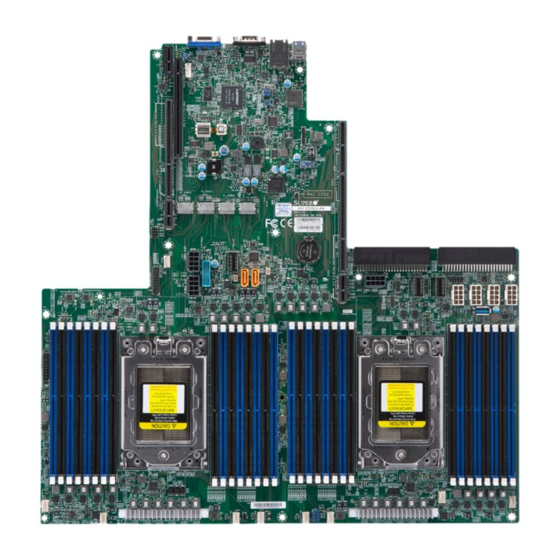
Chapter 1: Introduction H11DSU-iN User's Manual Quick Reference Figure 1-2. H11DSU-iN Motherboard Layout IPMI LAN COM1 COM1 USB0/1 JBR2 LED1 COM1 SXB1A JSDCARD1 JIPMB1 JUIDB2 Switch and UID LED JSDCARD1 SXB2 JSDCARD1 LEDM1 JPB1/JPG1/JWD1/ LEDM1 LEDM1 JBT1 SXB3A P2_NVME1 P1_NVME1... -
Page 7: Quick Reference Table
Chapter 1: Introduction H11DSU-iN User's Manual Connector Description Quick Reference Table VGA Video Port Jumper Description Default Setting Note: Jumpers in the table not described are for manufacturing testing purposes only and CPLD Code Programming are not covered in this manual. -
Page 8: Motherboard Features
Chapter 1: Introduction H11DSU-iN User's Manual Motherboard Features Motherboard Features Power Management Motherboard Features • ACPI power management (S5) • Power button override mechanism • Power-on mode for AC power recovery • Dual EPYC 7000 series, processor in Socket SP3 sockets... -
Page 9: Tel: 1.2 Processor And Chipset Overview
Built upon the functionality and capability of the EPYC 7000 series processor in an Socket SP3 H11DSU-iN IPMI LAN socket and a System on Chip chipset. The H11DSU-iN motherboard offers maximum I/O RJ45 AMD SP3 Rev. 1.02 expendability, energy efficiency, and data reliability in a 14-nm process architecture, and... -
Page 10: System Health Monitoring
1.4 System Health Monitoring 1.5 ACPI Features This section describes the health monitoring features of the H11DSU-iN motherboard. The ACPI stands for Advanced Configuration and Power Interface. The ACPI specification defines motherboard has an onboard chip that supports system health monitoring. Once a voltage a flexible and abstract hardware interface that provides a standard way to integrate power becomes unstable, a warning is given or an error message is sent to the screen. -
Page 11: Chapter 2 Installation
H11DSU-iN User's Manual Chapter 2: Installation Chapter 2 2.2 Motherboard Installation All motherboards have standard mounting holes to fit different types of chassis. Make sure that the locations of all the mounting holes for both the motherboard and the chassis match. -
Page 12: Installing The Motherboard
H11DSU-iN User's Manual Chapter 2: Installation Installing the Motherboard 1. Install the I/O shield into the back of the chassis. 2. Locate the mounting holes on the motherboard. See the previous page for the location. 3. Locate the matching mounting holes on the chassis. Align the mounting holes on the motherboard against the mounting holes on the chassis. -
Page 13: Processor And Heatsink Installation
External Cap. • Refer to the Supermicro website for updates on CPU support. Note: The Rail Frame is spring loaded, so keep a secure grip on it as you lift it so it does Installing the Processor and Heatsink not snap up. - Page 14 H11DSU-iN User's Manual Chapter 2: Installation 4. Remove the External Cap from the Rail Frame by pulling it upwards through the rail Note: You can only install the CPU inside the socket in one direction with the handle at the guides on the Rail Frame.
- Page 15 H11DSU-iN User's Manual Chapter 2: Installation 9. Gently lower the Force Frame down onto the Rail Frame and hold it in place until it is 11. After the Force Frame is secured and the CPU package is in place, now you must seated in the Socket housing.
-
Page 16: Memory Support And Installation
3. Reverse the procedure for installing the Force Frame onto the socket, unscrewing the The H11DSU-iN supports Up to 4 TB of ECC DDR4 2400/2666 MHz speed, RDIMM/ plate in the 3-2-1 screw order and lift the Force Frame to the vertical position. -
Page 17: Fax: Dimm Module Population Sequence
H11DSU-iN User's Manual Chapter 2: Installation DIMM Module Population Sequence DIMM Installation 1. Insert the desired number of DIMMs into When installing memory modules, the DIMM slots should be populated in the following order: DIMMA2, DIMMB2, DIMMC2, DIMMD2, DIMME2, DIMMF2, DIMMG2, DIMMH2, then... -
Page 18: Rear I/O Ports
H11DSU-iN User's Manual Chapter 2: Installation 2.5 Rear I/O Ports Universal Serial Bus (USB) Ports There are two USB 3.0 ports (USB0/1) on the I/O back panel. The motherboard also provides See Figure 2-1 below for the locations and descriptions of the various I/O ports on the rear two USB 3.0 connections via USB headers (USB3/4). -
Page 19: Front Control Panel
(with a setting in the BIOS - see Chapter 4). To turn off the power in the suspend with Supermicro chassis. See the figure below for the descriptions of the front control panel mode, press the button for at least 4 seconds. Refer to the table below for pin definitions. -
Page 20: Connectors
Note: UID can also be triggered via IPMI on the serverboard. For more information on IPMI, NMI Button please refer to the IPMI User's Guide posted on our website @ http://www.supermicro.com. The non-maskable interrupt button header is located on pins 19 and 20 of JF1. -
Page 21: Headers
SGPIO Header drive is not installed in the system. The SGPIO1 (Serial General Purpose Input/Output) header is used to communicate with the Please go to the following link for more information on TPM: http://www.supermicro.com/ enclosure management chip on the backplane. manuals/other/TPM.pdf. -
Page 22: How Jumpers Work
Pin 1 is identified with a square solder pad on the printed circuit board. See the diagram below for an example of jumping pins 1 and 2. Refer to the motherboard layout page for The H11DSU-iN has fourteen (14) SATA 3.0 ports (SATA0-13) that are supported by the jumper locations. -
Page 23: Led Indicators
H11DSU-iN User's Manual Chapter 2: Installation 2.9 LED Indicators VGA Enable/Disable JPG1 allows you to enable or disable the VGA port. The default position is on pins 1 and 2 LAN Port LEDs to enable VGA. See the table below for jumper settings. -
Page 24: Chapter 3 Troubleshooting
Chapter 3: Troubleshooting H11DSU-iN User's Manual Chapter 3 No Video 1. If the power is on but you have no video, remove all the add-on cards and cables. Troubleshooting 2. Use the speaker to determine if any beep codes exist. Refer to Appendix A for details on beep codes. -
Page 25: When The System Becomes Unstable
Note: Refer to the product page on our website at http:\\www.supermicro.com for memory 1. Please review the ‘Troubleshooting Procedures’ and 'Frequently Asked Questions' and CPU support and updates. -
Page 26: Frequently Asked Questions
Question: What type of memory does my motherboard support? Battery Removal Answer: The H11DSU-iN motherboard supports up to 4 TB of ECC DDR4 2400/2666 MHz To remove the onboard battery, follow the steps below: speed, RDIMM/LRDIMM/3DS/NVDIMM memory in thirty-two (32) slots. See Section 2.4 for details on installing memory. -
Page 27: Chapter 4 Bios
Main BIOS setup screen is shown below. The following Main menu items will be displayed: 4.1 Introduction This chapter describes the AMIBIOS™ Setup utility for the H11DSU-iN motherboard. The BIOS is stored on a chip and can be easily upgraded using a flash program. -
Page 28: Advanced Setup Configurations
H11DSU-iN User's Manual Chapter 4: BIOS Boot Feature CPLD Version This item displays the CPLD version of the BIOS ROM used in the system. Quiet Boot Memory Information Use this feature to select the screen display between the POST messages and the OEM logo Total Memory upon bootup. - Page 29 H11DSU-iN User's Manual Chapter 4: BIOS Restore on AC Power Loss Lock Legacy Resources Use this feature to set the power state after a power outage. Select Stay-Off for This setting Enables or Disables the ability to lock the legacy resources of the system.
- Page 30 H11DSU-iN User's Manual Chapter 4: BIOS Serial Port Console Redirection Flow Control Use this feature to set the flow control for Console Redirection to prevent data loss caused COM1 by buffer overflow. Send a "Stop" signal to stop sending data when the receiving buffer is full.
- Page 31 H11DSU-iN User's Manual Chapter 4: BIOS Bits per second Legacy Console Redirection Use this feature to set the transmission speed for a serial port used in Console Redirection. Legacy Console Redirection Settings Make sure that the same speed is used in the host computer and the client computer. A lower transmission speed may be required for long and busy lines.
- Page 32 H11DSU-iN User's Manual Chapter 4: BIOS Bits per Second PCIe/PCI/PnP Configuration This item sets the transmission speed for a serial port used in Console Redirection. Make This menu provides PCIe/PCI/PnP configuration settings and information. sure that the same speed is used in the host computer and the client computer. A lower transmission speed may be required for long and busy lines.
- Page 33 H11DSU-iN User's Manual Chapter 4: BIOS RSC-R1UW-E8R Slot 1 PCI-E x8 OPROM Maximum Payload This setting enables or disables the listed PCI/PCIX/PCIe Slot OPROM option. Options include This setting sets the maximum payload of the PCI Express device or allows the system Disabled, Legacy or EFI.
- Page 34 H11DSU-iN User's Manual Chapter 4: BIOS AtomicOp Requestor Enable Hardware Autonomous Width If supported by hardware and set to Enabled, this function initiates AtomicOp requests only If supported by hardware and set to Disabled, this will disable the hardware's ability to if the Bus Master Enable bit is in the Command Register set.
-
Page 35: Chipset
H11DSU-iN User's Manual Chapter 4: BIOS 4.4 Chipset Bank Interleaving This setting allows you to Enable or Disable Bank Interleaving for your system. This tab allows you to configure the following chipset settings for the system. Channel Interleaving This setting allows you to Enable or Disable Channel Interleaving for your system. -
Page 36: Amd Cbs
H11DSU-iN User's Manual Chapter 4: BIOS 4.5 AMD CBS Enable IBS This setting is used to configure for Enable IBS. Options include Auto, Disabled and This tab allows you to configure the following AMD CBS settings for the system. Enabled. - Page 37 H11DSU-iN User's Manual Chapter 4: BIOS Redirect Scrubber Control Memory Interleaving Size This setting enables Redirect Scrubber Control. Options include Disabled, Enabled and This setting controls the memory interleaving size. This determines the starting address Auto. of the interleave (bit 8, 9, 10 or 11). Options include 256 Bytes, 512 Bytes, 1 KB, 2 KB or Auto.
- Page 38 H11DSU-iN User's Manual Chapter 4: BIOS BankGroupSwap cTDP Control Use this setting to enable/disable BankGroupSwap. Options include Enabled, Disabled Use this setting to configure the cTDP Control. Options include Manual and Auto. and Auto. Address Hash Bank Use this setting to disable PSI. Options include Disable and Auto.
- Page 39 H11DSU-iN User's Manual Chapter 4: BIOS SD (Secure Digital) Options IO Enable Range 1 (2F8-2FF) Use this setting to enable/disable IO Range 1. Options include Enabled, Disabled SD Configuration Mode and Auto. Use this setting to configure the SD Configuration Mode. Options include Disabled, IO Enable Range 2 (3E8-3EF) Ver2.0, SdDump and Auto (Version 2.0 + Low Speed).
-
Page 40: Ipmi
H11DSU-iN User's Manual Chapter 4: BIOS 4.6 IPMI Erasing Settings Erase SEL This tab allows you to configure the following IPMI settings for the system. Select Yes, On next reset to erase all system event logs upon next system reboot. Select Yes, On every reset to erase all system event logs upon each system reboot. -
Page 41: Event Logs
H11DSU-iN User's Manual Chapter 4: BIOS 4.7 Event Logs Station IP Address This item displays the Station IP address for this computer. This should be in decimal and This tab allows the user to configure the following event logs settings for the system. -
Page 42: Security
H11DSU-iN User's Manual Chapter 4: BIOS 4.8 Security When Log is Full Select Erase Immediately to immediately erase all errors in the SMBIOS event log when This tab allows you to configure the following security settings for the system. the event log is full. Select Do Nothing for the system to do nothing when the SMBIOS event log is full. - Page 43 H11DSU-iN User's Manual Chapter 4: BIOS Secure Boot Mode Append Key Use this item to select the secure boot mode. The options are Standard and Custom. Select Yes to add the KEK from the manufacturer's defaults list to the existing KEK.
-
Page 44: Boot
H11DSU-iN User's Manual Chapter 4: BIOS 4.9 Boot OsRecovery Signature This item uploads and installs an OSRecovery Signature. You may select options for Use this tab to configure Boot Settings: Set New for a factory default key, or select Append to get it from a file. The file formats... -
Page 45: Save & Exit
H11DSU-iN User's Manual Chapter 4: BIOS 4.10 Save & Exit UEFI Application Boot Priorities This feature allows the user to specify which UEFI devices are boot devices. Select the Save & Exit tab to enter the Save & Exit BIOS Setup screen. - Page 46 H11DSU-iN User's Manual Save Changes After completing the system configuration changes, select this option to save the changes you have made. This will not reset (reboot) the system. Discard Changes Select this option and press <Enter> to discard all the changes and return to the AMI BIOS utility Program.
-
Page 47: Appendix A Software Installation A.1 Installing Software Programs
Appendix A Software Installation A.1 Installing Software Programs The Supermicro FTP site contains drivers and utilities for your system at ftp://ftp.supermicro. com. Some of these must be installed, such as the chipset driver. After accessing the FTP site, go into the CDR_Images directory and locate the ISO file for your motherboard. - Page 48 SMTP services to optimize the efficiency of your operation. Note: The default Username and Password for SuperDoctor 5 is admin / admin. Figure A-2. SuperDoctor 5 Interface Display Screen (Health Information) Note: The SuperDoctor 5 program and user’s manual can be downloaded from the Supermicro website at http://www.supermicro.com/products/nfo/sms_sd5.cfm.
-
Page 49: Standardized Warning Statements
The following statements are industry standard warnings, provided to warn the user of situations which have the potential for bodily injury. Should you have questions or experience difficulty, contact Supermicro's Technical Support department for assistance. Only certified technicians should attempt to install or configure components. - Page 50 Appendix C: Warning Statements H11DSU-iN User's Manual Product Disposal Attention Danger d'explosion si la pile n'est pas remplacée correctement. Ne la remplacer que par une pile de type semblable ou équivalent, recommandée par le fabricant. Jeter les piles usagées Warning! Ultimate disposal of this product should be handled according to all national conformément aux instructions du fabricant.
- Page 51 Warning: Do not upgrade the BIOS unless your system has a BIOS-related issue. Flashing 2. Insert the USB device that contains the new BIOS image ("Super.ROM") into your USB the wrong BIOS can cause irreparable damage to the system. In no event shall Supermicro drive and power on the system.
- Page 52 Appendix D: UEFI BIOS Recovery H11DSU-iN User's Manual 3. While powering on the system, please keep pressing <Ctrl> and <Home> simultaneously 5. When the screen as shown above displays, use the arrow keys to select the item on your keyboard until the following screen (or a screen similar to the one below) "Proceed with flash update"...
Need help?
Do you have a question about the H11DSU-iN and is the answer not in the manual?
Questions and answers