Table of Contents
Advertisement
Quick Links
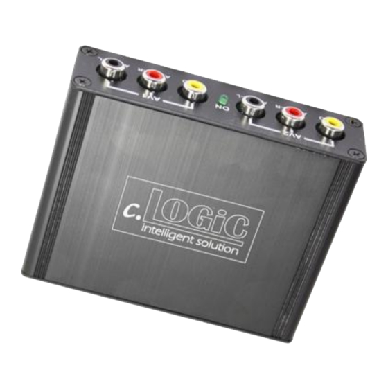
c.LOGiC Interface
CI-C2-MK-CD
Compatible with BMW Professional navigation
systems
without iDrive (MK2-MK4)
Product features
• Full plug and play multimedia interface
• 2 AV-inputs with separate IR-control channels
• control of after-market devices, e.g. DVB-T tuner, DVD-player, DVD-changer, ...
• after-market rear-view camera input (optional adapter is necessary)
• automatic switching to after-market rear-view camera input
• rear-view camera power (+12V max. 1A)
• Rear-seat-entertainment video-output for Video-sources connected to the c.LOGiC
• power-on remote-out trigger-signal (+12V max. 1A) to switch on connected devices
• video-in-motion
Version 20.09.2017
CI-C2-MK-CD
Advertisement
Table of Contents

Related Manuals for Car-Interface c.LOGiC CI-C2-MK-CD


Summary of Contents for Car-Interface c.LOGiC CI-C2-MK-CD
- Page 1 c.LOGiC Interface CI-C2-MK-CD Compatible with BMW Professional navigation systems without iDrive (MK2-MK4) Product features • Full plug and play multimedia interface • 2 AV-inputs with separate IR-control channels • control of after-market devices, e.g. DVB-T tuner, DVD-player, DVD-changer, … • after-market rear-view camera input (optional adapter is necessary) •...
-
Page 2: Table Of Contents
Contents 1. Prior to Installation 1.1. Delivery contents 1.2. Check compatibility of vehicle and accessories 2. Connection schema 3. Installation 3.1. Interconnecting interface-box and harnesses 3.2. Connections to the navigation computer or – if existing – to the TV-tuner 3.3. Connections to radio module 3.3.1. -
Page 3: Prior To Installation
Legal Information By law, watching moving pictures while driving is prohibited, the driver must not be distracted. We do not accept any liability for material damage or personal injury resulting, directly or indirectly, from installation or operation of this product. This product should only be used while standing or to display fixed menus or rear-view-camera video when the vehicle is moving, for example the MP3 menu for DVD upgrades. -
Page 4: Check Compatibility Of Vehicle And Accessories
1.2. Check compatibility of vehicle and accessories Requirements Vehicle 3series (E46), 5series (E39), 7series (E38), X5 (E53), X3 (E83), Z4 (E85/86) without AUX-input at the radio module (till approx 09/2002), Land Rover Range Rover (Vogue) L322 model years 2002-2005 Navigation Navigation system Professional without iDrive (MK2-MK4) Navigation system Professional MK3 in Land Rover Limitations... -
Page 5: Connection Schema
2. Connection schema Version 20.09.2017 CI-C2-MK-CD... -
Page 6: Installation
3. Installation Switch off ignition and disconnect the vehicle’s battery! If according to factory rules disconnecting the battery has to be avoided, it is usually sufficient to put the vehicle in sleep-mode. In case the sleep-mode does not show success, disconnect the battery with a resistor lead. -
Page 7: Interconnecting Interface-Box And Harnesses
3.1. Interconnecting interface-box and harnesses Plug harness C3C-BM701 into 14pin of interface-box C2C-M700. Plug female 18pin AMP connector of C3C-BM701 into male 18pin AMP connector of interface-box C2C-M700. Version 20.09.2017 CI-C2-MK-CD... -
Page 8: Connections To The Navigation Computer Or - If Existing - To The Tv-Tuner
3.2. Connections to the navigation computer or – if existing – to the TV-tuner If there is a factory TV-tuner inside the car, you have to connect the harness C3C-BM701 to the TV-tuner and not to the navigation computer! Disconnect blue female 18pin connector of vehicle harness from the back of the navigation computer or the factory TV-tuner (if existing and not removed). -
Page 9: Connections To Radio Module
3.3. Connections to radio module Picture exemplary for vehicles with Quadlock connector at factory radio module. 3.3.1. Exceptional case – Vehicles with factory DSP amplifier If the vehicle is with factory DSP amplifier, it is possible, that the CD-changer sound is not connected to the analogue input of the radio module, but to the digital input (44.1khz) of the factory DSP amplifier. -
Page 10: Radio Module With Quadlock Connector With Factory Cd-Changer
3.3.2. Radio module with Quadlock connector WITH factory CD-changer Loosen the female Quadlock connector to the radio module. Loosen the white female 12pin connector from chamber A of the female Quadlock connector. Vehicle female 12pin connector Push the insert from female 12pin connector’s plastic cap from the side. -
Page 11: Radio Module With Round-Pin Connector With Factory Cd-Changer
3.3.4. Radio module with round-pin connector WITH factory CD-changer Disconnect the audio cable from harness C3C-BM701 and remove pins from female and male 12pin connector. Loosen the female round-pin connector from the radio module. Loosen the female 10pin CD-changer connector of vehicle harness of the female round-pin connector. -
Page 12: Connecting Peripheral Devices
3.4. Connecting peripheral devices It is possible to connect up to 2 after-market AV-sources, after-market rear-view camera and rear-seat-entertainment to the c.LOGiC. Before final installation of the peripheral devices, we recommend to test-run the c.LOGiC functions to detect incompatibility of vehicle, navigation, factory accessories or peripheral devices as soon as possible. -
Page 13: Installing Av-Source's Ir-Sensor Additionally
Using the respective STA-xxx IR-control cable, interconnect the blue (yellow) female 3pin AMP connector of harness C3C-BM701 and the IR-port of the AV-source 1 (AV- source 2). Using an RCA-cable, interconnect the female RCA-port AV1 (AV2) of the interface-box C2C-M700 with the AV-output of the AV-source 1 (AV-source 2). The pink ACC-output wire (+12V max. -
Page 14: After-Market Rear-Seat-Entertainment
3.4.4. After-Market rear-seat-entertainment Using RCA-cables, connect the rear-seat-entertainment to the female RCA-connector VIDEO OUT of interface-box C2C-M700. Note: As the output is a full output, not shared with the video signal for the navigation system, splitting the video with an RCA Y-cable might give a good enough picture for two rear-seat-entertainment monitors. -
Page 15: Audio Settings
3.5.1. Audio settings It is necessary to set some audio settings to use the c.LOGiC interface. On vehicles WITH factory CD-changer set the audio setting to "CD" and "CD EMU OFF“. On vehicles WITHOUT factory CD-changer set the audio setting to "CD" and "CD EMU ON". 3.5.2. -
Page 16: Dip Switch Settings
3.6. DIP switch settings The default DIP switch setting is (already set): Check after installation the LED status on the C2C-M700 1+2 =OFF , 3 = ON interface. For this, turn off the ignition. After about 1-5min. (default setting) the status LED should turn off. If the status LED should not turn off, open the C2C-M700 housing, set the DIP switch “3”... -
Page 17: Operation
4. Operation 4.1. Activation of the video-in-motion function The video-in-motion function is permanently active without disturbing the navigation performance. 4.2. Selecting the c.LOGiC as current AV-source Selecting the c.LOGiC as current AV-source is activated by pressing the “MODE”-button (depending on the current mode of the system, it has to be pressed several times). -
Page 18: Button Assignment Table
4.6. Button assignment table The button assignment table shows which functions of the connected devices can be executed by navigation buttons. Once an AV-input is activated, the navigation button in the left column will execute the function described in the corresponding device column. The function description equals the remote control buttons of the device’s remote control. - Page 19 Button assignment table c.LOGiC C2-MK-CD Navigation DVB-T tuners usbLiNK DVD-player DVD- iPod®-control Analog-tuner button changer SOURCE Display 1 long Selection TV/ Selection Selection TV/ Selection TV/ Selection TV/ Selection TV/ image format image format image image format image format image format format OK / PLAY...
-
Page 20: Specifications
5. Specifications Operation voltage 10.5 – 14.8V DC Stand-by power drain <1mA Operation power drain 230mA Power consumption Temperature range -30°C to +80°C Weight 202g Measurements (box only) B x H x T 90 x 30 x 105 mm Legal disclaimer: Mentioned company and trademarks, as well as product names/codes are registered trademarks ®...
Need help?
Do you have a question about the c.LOGiC CI-C2-MK-CD and is the answer not in the manual?
Questions and answers