Advertisement
Quick Links
General Instructions
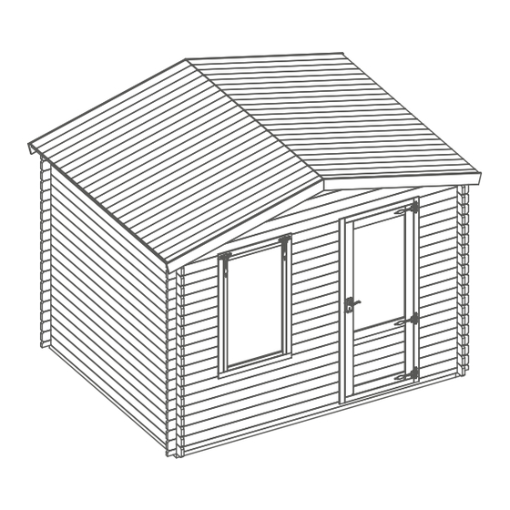
06LOG171SG-V1 & 06LOG171DG-V1 (3.3x2.6m)
06LOG171SG-V1: 3.3x2.6m 28mm apex cabin with single (glass) glazing.
06LOG171DG-V1: 3.3x2.6m 28mm apex cabin with double (glass) glazing.
BEFORE YOU START PLEASE READ INSTRUCTIONS CAREFULLY
- Check the pack and make sure you have all the parts listed.
- When you are ready to start, make sure you have the right tools at hand (not supplied)
including a Phillips screwdriver, Stanley knife, wood saw, step ladder and drill with 2mm
bit.
- Ensure there is plenty of space and a clean dry area for assembly.
TIMBER
As with all natural materials, timber can be a ected during various weather conditions.
For the duration of heavy or extended periods of rain, swelling of the wood panels may
occur. Warping of the wood may also occur during excessive dry spells due to an interior
moisture loss. Unfortunately, these processes cannot be avoided but can be helped. It is
suggested that the outdoor building is sprayed with water during extended periods of
warm sunshine and sheltered as much as possible during rain or snow.
Our buildings are pre treated with a water based treatment**; this only helps to protect
the product during transit and for upto 3 months against mould. To validate your
guarantee and ensure longevity of the product, it is ESSENTIAL the building is treated
with a wood preserver within the rst three months of assembly and thereafter in
accordance with the manufactures recommendations. Care must be taken to ensure
the product is placed on a suitable base.
BUILDING A BASE
When thinking about where the building and base is going to be constructed:
Ensure that there will be access to all sides for maintenance work and annual
treatment.
Ensure the base is level and is built on rm ground, to prevent distortion. Refer to
diagrams for the base dimensions, The base should be slightly smaller than the external
measurement of the building, i.e. The cladding should overlap the base, creating a run
o for water. It is also recommended that the oor be at least 25mm above the
surrounding ground level to avoid ooding.
TYPES OF BASE
- Concrete 75mm laid on top of 75mm hard-core.
- Slabs laid on 50mm of sharp sand.
Whilst all products manufactured are made to the highest standards of Safety and in
the case of childrens products independently tested to EN71 level, we cannot accept
responsibility for your safety whilst erecting or using this product.
Refer to the instructions pages for you speci c product code
Please retain product label and instructions for future reference
All building's should be
erected by two adults
For ease of assembly, you
MUST pilot drill all screw
holes and ensure all screw
heads are countersunk.
2mm Drill bit
For ease of assembly use a
rubber mallet to t the log
boards. Do NOT use a heavy
hammer.
It is advisable to use a
circular saw when cutting
roof and oor boards.
For assistance please contact customer care on: 01636 880514
Mercia Garden Products Limited,
Sutton On Trent,
Newark,
Nottinghamshire,
NG23 6QN
www.merciagardenproducts.co.uk
Winter = High Moisture = Expansion
Summer = Low Moisture = Contraction
CAUTION
Every e ort has been made during the
manufacturing process to eliminate the
prospect of splinters on rough surfaces of the
timber. You are strongly advised to wear gloves
when working with or handling rough sawn
timber.
Ensure to measure and check before cutting
boards.
P 1
Advertisement

Related Manuals for Mercia Garden Products 06LOG171SG-V1


Summary of Contents for Mercia Garden Products 06LOG171SG-V1
- Page 1 Summer = Low Moisture = Contraction erected by two adults 06LOG171SG-V1 & 06LOG171DG-V1 (3.3x2.6m) 06LOG171SG-V1: 3.3x2.6m 28mm apex cabin with single (glass) glazing. 06LOG171DG-V1: 3.3x2.6m 28mm apex cabin with double (glass) glazing. BEFORE YOU START PLEASE READ INSTRUCTIONS CAREFULLY For ease of assembly, you...
- Page 2 06LOG171SG-V1 & 06LOG171DG-V1 Please retain product label and instructions for future reference Overall Dimensions: Width = 3445mm Depth = 2632mm Roof Board - 121x16x1752mm QTY 48 Height = 2656mm MB16-1752mm Base Dimensions: Width = 3104mm Floor Board - 121x16x2350mm QTY 28...
- Page 3 Please retain product label and instructions for future reference Pre-assembly Step 2 *Please note: Fix the casement stay (No. 24) onto the window (No. 2) and the casement Each board interlocks at stay pins to the window cill using either end in a staggered pattern. 6x30mm screws per casement stay.
- Page 4 Please retain product label and instructions for future reference Step 4 Step 6 (See Pre-Assembly) IMPORTANT: It is imperative that you pre-drill before xing screws. Following the same method Following the same method outlined in Step 3, arrange the outlined in Pre-Assembly, lay remaining framing (No.
- Page 5 Please retain product label and instructions for future reference Step 8 (See Pre-Assembly) IMPORTANT: It is imperative that you pre-drill before xing screws. Step 10 (See Pre-Assembly) IMPORTANT: It is imperative that you pre-drill before xing screws. Following the same method Following the same method outlined in Pre-Assembly, lay outlined in Pre-Assembly, lay...
- Page 6 Please retain product label and instructions for future reference IMPORTANT: It is imperative that you pre-drill before xing screws. Step 12 (See Pre-Assembly) Step 13: Ridge Bar Fit Place the gable tops (No. 3) Align the ridge bar(s) (No. 16) into the onto the assembly.
- Page 7 Please retain product label and instructions for future reference Step 14 Step 15 Place the rst two roof board’s Ensuring the roof boards are ush (No. 10) onto the assembly on at the overhanging side and meet each side, making sure the boards at the apex, x the eaves frames are ush to the end of the roof (No.
- Page 8 Please retain product label and instructions for future reference Roof Step 16 Step 17 Place the rst oor board (No. 11) Inside the building place an internal inside the building ush to the log roof trim (No. 19) against the boarding board on one side.
- Page 9 Please retain product label and instructions for future reference Step 19 Step 20 Align the fascia’s (No. 12) Cut the felt into ve & strips lay onto the roof in the order shown in the with the roof and x into illustration.
- Page 10 Please retain product label and instructions for future reference Step 24 Arrange the storm braces (No. 17) around the building (internally). Place 2x storm braces per side xing into place using 2x80mm bolts per brace making sure the washer & nut are tightened from the outside of the building.
Need help?
Do you have a question about the 06LOG171SG-V1 and is the answer not in the manual?
Questions and answers