Kemppi FLEXLITE TX 133 Operation Manual
Hide thumbs
Also See for FLEXLITE TX 133:
- Operating manual (72 pages) ,
- Operating manual (72 pages) ,
- Operating manual (72 pages)
Table of Contents
Advertisement
Quick Links
Advertisement
Table of Contents

Subscribe to Our Youtube Channel
Related Manuals for Kemppi FLEXLITE TX 133


Summary of Contents for Kemppi FLEXLITE TX 133
- Page 1 Flexlite TX Operating manual - EN FLEXLITE TX © Kemppi 1/28 1920910 / 2002...
-
Page 2: Table Of Contents
6.5 Technical data TX 223 and TX 253 6.6 Technical data TX 225 and TX 255 6.7 Technical data TX 303 and TX 353 6.8 Technical data TX 305 and TX 355 7. Ordering codes © Kemppi 2/28 1920910 / 2002... -
Page 3: Flexlite Tx
Operating manual - EN 1. FLEXLITE TX These instructions describe the use of Kemppi's Flexlite TX TIG welding torches. Flexlite TX torches are designed for manual welding in demanding industrial use and they are compatible with Kemppi TIG welding equipment with 4- pin or 7-pin connectors. -
Page 4: About Equipment
K3 level torches differ from K5 level torches in connectors, for example. For information on K3 level torch connectors, refer to "Connecting torch" on page 11. 10. ON/OFF switch 11. Switch cover 12. Torch handle © Kemppi 4/28 1920910 / 2002... - Page 5 The serial number and other device-related identification information may also be saved in the form of a QR code (or a barcode) on the device. Such code can be read by a smartphone camera or with a dedicated code reader device providing fast access to the device-specific information. © Kemppi 5/28 1920910 / 2002...
-
Page 6: Installation
This chapter describes a typical Flexlite TX welding torch assembly. The details shown may vary depending on the exact torch setup. Install the insulating ring and collet body. Some Flexlite TX torch models also include a back cap insulating ring, in addition to the gas nozzle insulating ring. © Kemppi 6/28 1920910 / 2002... - Page 7 Prior to installing the tungsten electrode, grind the electrode tip to the appropriate dimensions for your weld- ing application. For more information, refer to the section "Electrode tip" on page 15. Push the electrode into the torch and through the collet and gas nozzle. © Kemppi 7/28 1920910 / 2002...
-
Page 8: Installing Torch Remote
Ensure that the welding equipment is not connected to the mains or that the welding torch is not connected to the welding machine at this stage. Open the switch cover by releasing the screws in the rear section of the cover and remove the cover. © Kemppi 8/28 1920910 / 2002... -
Page 9: Installing Start Switch Extension
Secure the switch cover in place with the two screws in the rear section of the cover. 3.3 Installing start switch extension The standard ON/OFF switch can be replaced with an extended start switch. © Kemppi 9/28 1920910 / 2002... - Page 10 Open the switch cover by releasing the screws in the rear section of the cover and remove the cover. Replace the standard start switch button on the cover with the extended start switch button. © Kemppi 10/28 1920910 / 2002...
-
Page 11: Connecting Torch
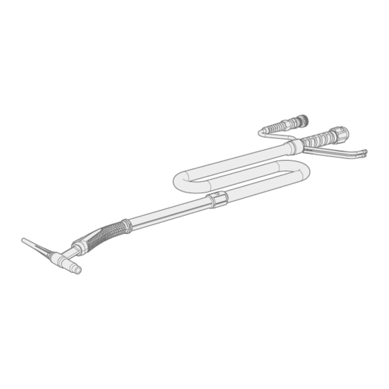
For connecting the torch, refer also to your welding equipment’s instructions. Gas-cooled TIG torch (K5 level) Connect the welding cable and the control cable to the power source. Secure by turning the connectors clock- wise. © Kemppi 11/28 1920910 / 2002... - Page 12 Connect the welding cable and the control cable to the power source. Secure by turning the connectors clock- wise. Connect the coolant inlet and outlet hoses to the cooling unit. Note that the connectors are color-coded. © Kemppi 12/28 1920910 / 2002...
- Page 13 With K3 level torches that have a DIX connector, use a separate gas hose for gas connection. Make sure to connect the coolant hoses to the correct hose connectors. If the connections cross, the torch and torch body may overheat. © Kemppi 13/28 1920910 / 2002...
-
Page 14: Operation
The welding current setting defines the electrode size and the shielding gas flow rate. The most typical shielding gas for TIG welding is argon. The following tables provide some basic guidance for the electrode size and shielding gas flow rate selection. © Kemppi 14/28 1920910 / 2002... -
Page 15: Electrode Tip
Sharpening principle: Where I = 1…5 x d. The sharpening length best suited for your purposes depends on the most used welding current level: Low currents Mid currents High currents © Kemppi 15/28 1920910 / 2002... - Page 16 The welding current is too high for the electrode diameter selected. When using Kemppi AC TIG equipment for specific applications, it is also possible to prepare and maintain a small point on the electrode tip (d). This improves the directional control of the welding arc and weld pool size.
-
Page 17: Maintenance
Use the correct tension torque when fastening loose parts. Do not use pressure washing devices. Service workshops Kemppi Service Workshops complete the welding system maintenance according to the Kemppi service agreement. The main aspects in the service workshop maintenance procedure are: •... -
Page 18: Troubleshooting
5.1 Troubleshooting The problems and the possible causes listed are not definitive, but suggest some typical situations that may turn up during normal use of the welding system. For further information and assistance, contact your nearest Kemppi service workshop. General: The welding system does not power up •... -
Page 19: Disposal Of Machine
The owner of the equipment is obliged to deliver a decommissioned unit to a regional collection center, as per the instructions of local authorities or a Kemppi representative. By applying these European Directives you improve the environment and human health. -
Page 20: Technical Data
1.0…2.4 Load capacity @ 40 % (Argon) Load capacity @ 100 % (Argon) Operating temperature range (°C) °C -10…+40 °C Storage temperature range °C -40…+60 °C Minimum cooling power at 1.0 l/min Remote control © Kemppi 20/28 1920910 / 2002... -
Page 21: Technical Data Tx 135
Load capacity @ 100 % (Argon) Operating temperature range (°C) °C -10…+40 °C Storage temperature range °C -40…+60 °C Minimum cooling power at 1.0 l/min Remote control Optional Neck type Bendable This equipment complies with standard IEC 60974-7. © Kemppi 21/28 1920910 / 2002... -
Page 22: Technical Data Tx 163
6.4 Technical data TX 165 Flexlite TX 165GF 165GS 165G Feature Value Type of cooling Coolant flow rate (l/min) l/min Coolant pressure (min) Coolant pressure (max) Arc striking voltage Rating of electrical components (remote, nominal) © Kemppi 22/28 1920910 / 2002... -
Page 23: Technical Data Tx 223 And Tx 253
Minimum cooling power at 1.0 l/min 1.0 kW Remote control Neck type 70° angle Rotating 70° angle Rotating * Use a separate gas hose for gas connection. This equipment complies with standard IEC 60974-7. © Kemppi 23/28 1920910 / 2002... -
Page 24: Technical Data Tx 225 And Tx 255
This equipment complies with standard IEC 60974-7. 6.7 Technical data TX 303 and TX 353 Flexlite TX 303WF 353W Feature Value Type of cooling Liquid Liquid Coolant flow rate (l/min) l/min Coolant pressure (min) Coolant pressure (max) Arc striking voltage © Kemppi 24/28 1920910 / 2002... -
Page 25: Technical Data Tx 305 And Tx 355
6.8 Technical data TX 305 and TX 355 Flexlite TX 305WF 355W Feature Value Type of cooling Liquid Liquid Coolant flow rate (l/min) l/min Coolant pressure (min) Coolant pressure (max) Arc striking voltage Rating of electrical components (remote, nominal) © Kemppi 25/28 1920910 / 2002... - Page 26 Storage temperature range °C -40…+60 °C -40…+60 °C Minimum cooling power at 1.0 l/min 1.0 kW 1.0 kW Remote control Optional Optional Neck type Bendable 70° angle This equipment complies with standard IEC 60974-7. © Kemppi 26/28 1920910 / 2002...
-
Page 27: Ordering Codes
Flexlite TX 253WS TX253WS4 TX253WS8 Flexlite TX 255WS TX255WS4 TX255WS8 TX255WS16 Flexlite TX 255WSN TX255WSN8 Flexlite TX 303WF TX303WF8 Flexlite TX 305WF TX305WF4 TX305WF8 TX305WF16 Flexlite TX 305WFN TX305WFN8 Flexlite TX 353W TX353W4 TX353W8 TX353W16 © Kemppi 27/28 1920910 / 2002... - Page 28 TXR10W TXR10G Flexlite TXR20 remote, rocker switch TXR20W TXR20G Flexlite TX other accessories (optional) Product Ordering code Flexlite TX trigger extension SP014802 Adapter R1/4 to DIX 9mm SP016758 Adapter R1/4 to DIX 13mm SP016759 © Kemppi 28/28 1920910 / 2002...
Need help?
Do you have a question about the FLEXLITE TX 133 and is the answer not in the manual?
Questions and answers