
Related Manuals for Kemppi DCM


Summary of Contents for Kemppi DCM
- Page 1 DCM Kemppi Cobotics Operating manual - EN DIGITAL CONNECTIVITY MODULE (DCM) / Kemppi Cobotics Operating manual © Kemppi 1922170 / 2325...
-
Page 2: Table Of Contents
CONTENTS 1. General 1.1 Equipment description 2. Installation 2.1 Mounting on equipment 2.2 Connecting cables 2.3 Installing Kemppi Cobotics application 3. Operation 3.1 Pairing with mobile device 3.2 DCM settings 3.3 Status information 3.4 Fieldbus control tables 3.4.1 Setting control bit states to start welding 3.5 Timing diagrams... -
Page 3: General
Together with the Kemppi Cobotics application, it forms a connection between the welding equip- ment and robot / cobot (collaborative robot) via the Modbus TCP fieldbus (in the setup, DCM is a Modbus TCP slave device). -
Page 4: Equipment Description
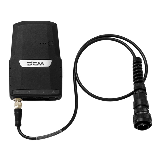
USB connector * Power connector * Ethernet connector Mounting tape. * Not needed for normal operation. DCM is powered through the CAN connection. LEDs explained Red / yellow / green: Additional notification light. (A) Green: Lit when the power is on. (B) Blue: Blinks infrequently when ready and available, blinks more frequently when in "beacon mode", is lit con-... - Page 5 DCM Kemppi Cobotics Operating manual - EN EQUIPMENT IDENTIFICATION Serial number Serial number of the device is marked on the rating plate or in another distinctive location on the device. Quick Response (QR) code The serial number and other device-related identification information may also be saved in the form of a QR code (or a barcode) on the device.
-
Page 6: Installation
Do not power on the equipment before the installation is complete. Before installation Check the contents of the packages and make sure the parts are not damaged. "Mounting on equipment" on the next page "Connecting cables" on page 9 "Installing Kemppi Cobotics application" on page 10 © Kemppi 1922170 / 2325... -
Page 7: Mounting On Equipment
Operating manual - EN 2.1 Mounting on equipment The DCM device can be fixed on the side of a power source or a wire feeder either with the factory-fitted mounting tape or with an optional DIN rail. The mounting tape can be used on any clean and suitable surface. The mounting tape counterparts are attached together on delivery. - Page 8 Operating manual - EN Let the mounting tape's adhesive cure for 30 minutes. Due to the velcro-type mounting tapes, it is now possible to detach and attach the DCM device if needed. Mounting on DIN rail (optional) Note that the rail installation typically requires drilling fixing holes on the fixing surface for the rail itself. This is not covered by this instruction.
-
Page 9: Connecting Cables
Unused DCM connectors are covered. Leave the covers in place. Connect the CAN cable to the power source or wire feeder. Connect the other end of the CAN cable to the DCM (1). Secure the cable by turning the cable coupling firmly on the connector threads. -
Page 10: Installing Kemppi Cobotics Application
Welding settings are configured in the welding system's control panel. For Kemppi Cobotics application, a DCM firmware version 1.00.92.0 or newer is required. (For welding equipment firm- ware versions, refer to "General" on page 3.) Scan the QR code below or search for 'Kemppi Cobotics' in Google's Play Store. -
Page 11: Operation
DCM Kemppi Cobotics Operating manual - EN 3. OPERATION "Pairing with mobile device" on the next page "DCM settings" on page 13 "Status information" on page 14 "Fieldbus control tables" on page 16 "Timing diagrams" on page 21 "Resetting" on page 23 "Updating DCM" on page 24 ©... -
Page 12: Pairing With Mobile Device
If there are several DCM devices available to choose from and you are uncertain which is which, you can press the function button on the DCM device briefly (1 sec.) to turn on its beacon. A blue indicator is shown next to the device in question. -
Page 13: Dcm Settings
Operating manual - EN 3.2 DCM settings This section describes how to configure the DCM settings with the Kemppi Cobotics application. Select the parameter for adjusting. >> Depending on the parameter to be adjusted, refer also to the Settings parameters table below for more details. -
Page 14: Status Information
DCM Kemppi Cobotics Operating manual - EN 3.3 Status information In the Kemppi Cobotics application you can view the communication between the welding system and the robot. Parameter Description General Communication Green light: Communication between the welding system and the robot has been established. - Page 15 DCM Kemppi Cobotics Operating manual - EN Wire inch forward Green light: The wire inch forward function is ON. No light: The wire inch forward function is OFF. Wire inch back- Green light: The wire inch backward function is ON.
-
Page 16: Fieldbus Control Tables
This section describes the Modbus TCP fieldbus control tables. For information on setting the control bit states for starting welding, refer to "Setting control bit states to start welding" on page 20. Fieldbus control tables "Kemppi Cobot" fieldbus control table, control parameters: Register (word) Coil Data type... - Page 17 DCM Kemppi Cobotics Operating manual - EN WeldingSystemAccess (Not in use) (Not in use) (Not in use) (Not in use) (Not in use) (Not in use) (Not in use) UINT16 TAST UINT16 WeldingWireFeedSpeed UINT16 WeldingVoltage UINT16 WeldingCurrent UINT16 ErrorNumber UINT16...
- Page 18 Watchdog If you set a value for the watchdog RobotControlMode = timeout parameter (in the Kemppi Cobot- ics application), the robot must toggle the watchdog control bit between states 1 and 0 continuously when the robot control mode is enabled. If the robot...
- Page 19 DCM Kemppi Cobotics Operating manual - EN Status parameters: Parameter Parameter name Description (bus) value value WeldingWireFeedSpeed Measured welding wire feed speed. 0 ... 25.5 0 ... 255 m/min WeldingVoltage Measured welding (terminal) voltage. 0 ... 6553.5 V 0 ...
-
Page 20: Setting Control Bit States To Start Welding
DCM Kemppi Cobotics Operating manual - EN PowerSourceReady Indicates whether the power source is ready to Power source is busy Power source is ready start a new weld. The power source is ready for a new weld when the robot has not requested welding and crater fill is not ongoing. -
Page 21: Timing Diagrams
DCM Kemppi Cobotics Operating manual - EN 3.5 Timing diagrams "Welding start and stop timing" below "Memory channel change timing" on the next page "Wire inch timing" on the next page 3.5.1 Welding start and stop timing Welding start timing... -
Page 22: Memory Channel Change Timing
DCM Kemppi Cobotics Operating manual - EN 3.5.2 Memory channel change timing Description Typical Units Total time 3.5.3 Wire inch timing This section describes the timing for the wire inch forward and wire inch backward functions when controlled by the robot. -
Page 23: Resetting
Operating manual - EN 3.6 Resetting The DCM can be reset to factory settings with a long-press of the button on the module. Ensure that the DCM is ready and available: Blue LED (C) blinks infrequently. Press the button on the DCM device for 30 seconds: >>... -
Page 24: Updating Dcm
Remove the USB memory stick from the DCM’s USB connector. >> DCM will automatically reboot. Keep the DCM turned on for at least 1 minute. This allows the DCM to set the installed firmware as default. >> The update is now complete. -
Page 25: Technical Data
DCM Kemppi Cobotics Operating manual - EN 4. TECHNICAL DATA Feature Description Value Operating voltage 12...48 V Operating temperature range -20...40 °C Degree of protection IP class IP24 External dimensions LxWxH 30 x 104 x 171 Weight without accessories 0.235 kg Wireless communication type 2.4 GHz, dual mode... -
Page 26: Ordering Codes
DCM Kemppi Cobotics Operating manual - EN 5. ORDERING CODES Product Ordering code Digital Connectivity Module (DCM) 6265051 © Kemppi 1922170 / 2325...
Need help?
Do you have a question about the DCM and is the answer not in the manual?
Questions and answers