Table of Contents
Advertisement
Quick Links
Advertisement
Table of Contents

Related Manuals for Kemppi Flexlite GX Series


Summary of Contents for Kemppi Flexlite GX Series
- Page 1 Flexlite GX Operating manual - EN Flexlite GX © Kemppi 1921390 / 2310...
-
Page 2: Table Of Contents
6.6 Technical data: Flexlite GX 500A/520A (water-cooled) 6.7 Technical data: Flexlite GX 600A (water-cooled) 6.8 Technical data: Flexlite GX HD 300A (gas-cooled) 6.9 Technical data: Flexlite GX HD 400A (gas-cooled) 6.10 Component selection 7. Ordering codes © Kemppi 1921390 / 2310... -
Page 3: General
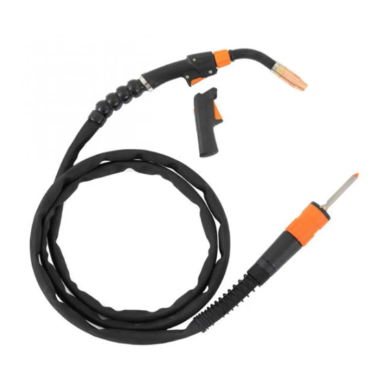
Operating manual - EN 1. GENERAL These instructions describe the use of Kemppi's Flexlite GX MIG welding guns. Flexlite GX welding guns are designed for professional manual welding. Flexlite GX range covers both water-cooled and gas-cooled models for MIG welding. Flexl- ite GX welding guns are available in three different series –... - Page 4 While every effort has been made to ensure that the information contained in this guide is accurate and com- plete, no liability can be accepted for any errors or omissions. Kemppi reserves the right to change the spe- cification of the product described at any time without prior notice. Do not copy, record, reproduce or transmit the contents of this guide without prior permission from Kemppi.
-
Page 5: About Equipment
Trigger switch Cover plate >> This covers the handle if a welding gun remote is not used (Flexlite GX series 5 and series 8 models). For more information on the gun remotes, refer to "Installing gun remote" on page 9. >> Not available with Flexlite GX series 3 models. - Page 6 Device-related information or a web link to such information may be found in the form of a QR code on the device. The code can be read, for example, with a mobile device camera and a QR code application. © Kemppi 1921390 / 2310...
-
Page 7: Installation
Before installation and use Ensure compliance with your local and national safety requirements regarding the installation and use of high voltage units. Check the contents of the packages and make sure the parts are not damaged. © Kemppi 1921390 / 2310... -
Page 8: Assembling Gun
With multi-neck gun models only: Attach the assembled neck to the gun body. Secure with the neck tightening collar. Hand-tighten the neck tightening collar only. Over-tightening and/or using a tool can damage the gun components. © Kemppi 1921390 / 2310... -
Page 9: Installing Gun Remote
The Flexlite GX series 5 welding gun remote (GXR10) can be used with Kemppi Fastmig equipment only. The Flexlite GX series 8 welding gun and digital gun remote (GXR80B) can be used with Kemppi X8 MIG Welder only. Ensure that the welding equipment is not connected to the mains or that the welding gun is not connected at this stage. - Page 10 Set the new gun remote control cover against the gun body slightly off to the front and slide it backward so that the connectors (*) align and connect. Secure the remote control cover in place with the screws from the sides. © Kemppi 1921390 / 2310...
-
Page 11: Connecting Gun
Water-cooled models only: Connect the coolant inlet and outlet hoses to your welding equipment. Note that the connectors are color-coded. Make sure to connect the coolant hoses to the correct hose connectors. If the connections cross, the welding gun may overheat. © Kemppi 1921390 / 2310... -
Page 12: Installing And Replacing Wire Liner
Removing and inserting wire liner This same method applies to both Euro connector (GX series 3 and 5) and Kemppi connector (GX series 8) welding guns, but the visual details may vary. The method is the same also for both gas- and water-cooled welding guns. - Page 13 (*). Remove that also. Remove the old wire liner from the cable hose. If you still plan to use the same wire liner later, make sure not to damage the wire liner at this stage. © Kemppi 1921390 / 2310...
- Page 14 "Installing sleeve assembly and cutting wire liner (Euro connector: series 3 and series 5 welding guns)" below or "Installing sleeve assembly and cutting wire liner (Kemppi connector: series 8 welding guns)" on the next page. Installing sleeve assembly and cutting wire liner (Euro connector: series 3 and series 5 welding guns) The method is the same for both gas- and water-cooled welding guns.
- Page 15 Insert the retainer cone and sleeve nut (without end cap) on the wire liner and secure them in place. Tighten to 12 Nm torque. All series 8 Flexlite GX models (Kemppi connector) include a longer wire liner sleeve. The series 8 GMN, WS and 608W models include also an additional sealing ring (*): ©...
-
Page 16: Replacing Steel Wire Liner
Removing and inserting wire liner This same method applies to both Euro connector (GX series 3 and 5) and Kemppi connector (GX series 8) welding guns, but the visual details may vary. The method is the same also for both gas- and water-cooled welding guns. - Page 17 (*). Remove that also. Remove the old wire liner from the cable hose. If you still plan to use the same wire liner later, make sure not to damage the wire liner at this stage. © Kemppi 1921390 / 2310...
- Page 18 "Installing sleeve assembly and cutting wire liner (Euro connector: series 3 and 5 welding guns)" below or "Installing sleeve assembly and cutting wire liner (Kemppi connector: series 8 welding guns)" on the next page. Installing sleeve assembly and cutting wire liner (Euro connector: series 3 and 5 welding guns) The method is the same for both gas- and water-cooled welding guns.
- Page 19 Place the sleeve nut on the wire liner and secure it in place. Tighten to 12 Nm torque. Installing sleeve assembly and cutting wire liner (Kemppi connector: series 8 welding guns) The method is the same for both gas- and water-cooled welding guns, except for the additional sealing ring with the below- mentioned models.
- Page 20 Insert the retainer cone and sleeve nut (without the end cap) on the wire liner and secure them in place. Tighten to 12 Nm torque. Series 8 Flexlite GX models (Kemppi connector) include a longer wire liner sleeve. The series 8 GMN, WS and 608W models include also an additional sealing ring (*): Cut the wire liner leaving 1-2 mm of excess liner measured from the sleeve nut end.
-
Page 21: Replacing Wire Liner For Multi-Neck
With Flexlite GX multi-neck welding guns the wire liner needs to be replaced separately for the neck. For more inform- ation on wire liner replacement in general, refer to "Replacing steel wire liner" on page 16 and "Replacing DL Chili wire liner" on page 12. Remove the neck. © Kemppi 1921390 / 2310... - Page 22 Release the neck liner fastener and remove the old neck wire liner. Insert the new neck wire liner into the neck and ensure that it goes all the way through and the liner's end(*) sits firmly in its housing. Secure with the fastener. © Kemppi 1921390 / 2310...
- Page 23 Flexlite GX Operating manual - EN Attach the assembled neck to the gun body. Secure with the neck tightening collar. Hand-tighten only. Over-tightening and/or using a tool can damage the gun components. © Kemppi 1921390 / 2310...
-
Page 24: Trigger Switch Replacement
In normal use, the trigger switch replacement is not a frequent task. However, removing the trigger switch tem- porarily may be necessary, for example, when using a series 5 Flexlite GX welding gun with other than Kemppi Fast- mig equipment. -
Page 25: Trigger Switch Setting (Gx Series 5) - W015263 Until 9/2020
(e.g. A or B). Refer to the label on the circuit board for version information: Series 5 Flexlite GX welding guns are designed and set up for Kemppi Fastmig equipment by default (circuit board W015263 until 9/2020). The secondary trigger switch setting provides only limited support for other than Kemppi Fastmig welding equipment. -
Page 26: Trigger Switch Setting (Gx Series 5) - W015263 Since 10/2020
Refer to the label on the circuit board for version information: The series 5 Flexlite GX welding guns are designed and set up for Kemppi Fastmig, Pro and Kempact Pulse equipment by default (since trigger switch circuit board version R04 (10/2020)). The secondary trigger switch setting provides general support also for other than the above-mentioned Kemppi welding equipment. - Page 27 - Fitweld - Kemppi Pro - X3 MIG Welder - Kempact RA - Other than Kemppi Tools needed: For changing the setting: Detach the trigger switch. Refer to "Trigger switch replacement" on page 24 for more detailed instructions. Release the small screw holding the trigger switch circuit board and remove the circuit board.
-
Page 28: Trigger Switch Setting (Gx Series 5) - W022322
This instruction applies to series 5 trigger switch circuit board W022322. Refer to the label on the circuit board for ver- sion information: The series 5 Flexlite GX welding guns are designed and set up for Kemppi Fastmig, Pro and Kempact Pulse equipment by default (trigger switch circuit board W022322). The secondary trigger switch setting provides general support also for other than the above-mentioned Kemppi welding equipment. - Page 29 Set the two dip switches on the circuit board to the correct position (refer to the settings diagram above). Reassemble and reinstate the trigger switch. Refer to "Trigger switch replacement" on page 24 for more detailed instructions. © Kemppi 1921390 / 2310...
-
Page 30: Installing And Removing Grip Handle (Optional)
Keeping the bottom of the grip handle pointing forward, fit the inside grooves of the grip handle over the screws on the gun. Pull the handle backward to lock it in position. To remove the grip handle, press the unlock button in the grip handle rear: © Kemppi 1921390 / 2310... -
Page 31: Adjusting And Tightening Neck (Gas-Cooled Models)
Tighten or loosen the neck retaining nut with a spanner so that it is either possible to adjust the neck position by hand or tighten the nut so that it secures the neck into the desired welding position. © Kemppi 1921390 / 2310... -
Page 32: Operation
"Using gun remote GXR10 (series 5)" on the next page "Using gun remote GXR80B (series 8)" on page 34 For more information on component selection and availability, refer to "Component selection" on page 60 and "Order- ing codes" on page 62. © Kemppi 1921390 / 2310... -
Page 33: Using Gun Remote Gxr10 (Series 5)
4.1 Using gun remote GXR10 (series 5) The Flexlite GX series 5 welding gun remote can be used with Kemppi Fastmig equipment only. Adjust the wire feed speed or change the memory channel by turning the roller switch on the gun handle. -
Page 34: Using Gun Remote Gxr80B (Series 8)
Operating manual - EN 4.2 Using gun remote GXR80B (series 8) The Flexlite GX welding gun's GXR80B gun remote can be used with Kemppi X8 MIG Welder only. The remote control is disabled if TIG, MMA or gouging mode is used. - Page 35 +/- buttons. Long press of a +/- button scrolls the parameter values faster. Long press of the right arrow button switches between double pulse, double process and WP switch parameter sets, if one of these features or processes is in use. © Kemppi 1921390 / 2310...
-
Page 36: Maintenance
• Check regularly that all the components are tightly fastened. • Check that the current transfer surface on the Kemppi gun adapter is clean and unscratched, and the connector pins are straight and undamaged. • Check the protective hose on the cable for damage. - Page 37 Flexlite GX Operating manual - EN Find your closest service workshop at Kemppi website. © Kemppi 1921390 / 2310...
-
Page 38: Troubleshooting
5.1 Troubleshooting The problems and the possible causes listed are not definitive, but suggest some typical situations that may turn up during normal use of the welding system. For further information and assistance, contact your nearest Kemppi ser- vice workshop. - Page 39 Flexlite GX Operating manual - EN • Make sure you are using original Kemppi consumable and spare parts. Incorrect spare part materials may cause the overheating of the neck. The welding gun connector overheats • Make sure the connector is properly connected to the wire feeder.
-
Page 40: Disposal
The owner of the equip- ment is obliged to deliver a decommissioned unit to a regional collection center, as per the instructions of local author- ities or a Kemppi representative. By applying these European Directives you improve the environment and human health. -
Page 41: Technical Data
"Technical data: Flexlite GX HD 300A (gas-cooled)" on page 56 "Technical data: Flexlite GX HD 400A (gas-cooled)" on page 58 For component selection, refer to "Component selection" on page 60. For ordering codes, refer to "Ordering codes" on page 62. © Kemppi 1921390 / 2310... -
Page 42: Technical Data: Flexlite Gx 200A/250A (Gas-Cooled)
-40°C…+60°C Pistol grip handle Rotating neck Changeable neck Neck dimensions: Length x (mm) ( see figure below ) Height y (mm) ( see figure below ) Neck angle ɑ (°) ( see figure below ) © Kemppi 1921390 / 2310... - Page 43 Operating manual - EN Standards IEC 60974-7 IEC 60974-7 IEC 60974-7 Gun length (m) 3.5 / 5 3.5 / 5 3.5 / 5 * Measured using the longest gun length available. Neck dimensions, G-models: Neck dimensions, MN-models: © Kemppi 1921390 / 2310...
-
Page 44: Technical Data: Flexlite Gx 300A/350A (Gas-Cooled)
0.9...1.2 0.8...1.2 0.8...1.2 0.8...1.2 Operating temperature range -20°C…+40°C -20°C…+40°C -20°C…+40°C -20°C…+40°C Storage temperature range -40°C…+60°C -40°C…+60°C -40°C…+60°C -40°C…+60°C Pistol grip handle Rotating neck Changeable neck Neck dimensions: Length x (mm) ( see figure below ) © Kemppi 1921390 / 2310... - Page 45 IEC 60974-7 IEC 60974-7 IEC 60974-7 IEC 60974-7 Gun length (m) 3.5 / 5 3.5 / 5 6 / 8 3.5 / 5 * Measured using the longest gun length available. Neck dimensions, G-models: Neck dimensions, MN-models: © Kemppi 1921390 / 2310...
-
Page 46: Technical Data: Flexlite Gx 250A/300A (Water-Cooled)
-40°C…+60°C Pistol grip handle Rotating neck Changeable neck Neck dimensions: Length x (mm) ( see figure below ) Height y (mm) ( see figure below ) Neck angle ɑ (°) ( see figure below ) © Kemppi 1921390 / 2310... - Page 47 Flexlite GX Operating manual - EN Standards IEC 60974-7 IEC 60974-7 Gun length (m) 3.5 / 5 * Measured using the longest gun length available. Neck dimensions, W-models: © Kemppi 1921390 / 2310...
-
Page 48: Technical Data: Flexlite Gx 400A (Gas-Cooled)
-40°C…+60°C Pistol grip handle Rotating neck Changeable neck Neck dimensions: Length x (mm) ( see figure below ) Height y (mm) ( see figure below ) Neck angle ɑ (°) ( see figure below ) © Kemppi 1921390 / 2310... - Page 49 Flexlite GX Operating manual - EN Standards IEC 60974-7 IEC 60974-7 Gun length (m) 3.5 / 5 3.5 / 5 * Measured using the longest gun length available. Neck dimensions, G-models: Neck dimensions, MN-models: © Kemppi 1921390 / 2310...
-
Page 50: Technical Data: Flexlite Gx 300A/400A/420A (Water-Cooled)
0.9...1.6 0.8...1.6 1.0...1.2 0.8...1.6 1.2...1.6 Ss-MC/FC 0.9...1.6 0.9...1.6 0.8...1.6 1.2...1.6 0.8...1.6 1.2...1.6 Operating temperature range -20°C…+40°C -20°C…+40°C -20°C…+40°C -20°C…+40°C Storage temperature range -40°C…+60°C -40°C…+60°C -40°C…+60°C -40°C…+60°C Pistol grip handle Rotating neck Changeable neck Neck dimensions: © Kemppi 1921390 / 2310... - Page 51 Neck angle ɑ (°) ( see figure below ) Standards IEC 60974-7 IEC 60974-7 IEC 60974-7 IEC 60974-7 Gun length (m) 3.5 / 5 6 / 8 3.5 / 5 * Measured using the longest gun length available. Neck dimensions, W-models: © Kemppi 1921390 / 2310...
-
Page 52: Technical Data: Flexlite Gx 500A/520A (Water-Cooled)
-20°C…+40°C -20°C…+40°C Storage temperature range -40°C…+60°C -40°C…+60°C Pistol grip handle Rotating neck Changeable neck Neck dimensions: Length x (mm) ( see figure below ) 145 / 245 Height y (mm) ( see figure below ) © Kemppi 1921390 / 2310... - Page 53 Operating manual - EN Neck angle ɑ (°) ( see figure below ) Standards IEC 60974-7 IEC 60974-7 Gun length (m) 3.5 / 5 3.5 / 5 * Measured using the longest gun length available. Neck dimensions, W-models: © Kemppi 1921390 / 2310...
-
Page 54: Technical Data: Flexlite Gx 600A (Water-Cooled)
Operating temperature range -20°C…+40°C -20°C…+40°C Storage temperature range -40°C…+60°C -40°C…+60°C Pistol grip handle Rotating neck Changeable neck Neck dimensions: Length x (mm) ( see figure below ) Height y (mm) ( see figure below ) © Kemppi 1921390 / 2310... - Page 55 Flexlite GX Operating manual - EN Neck angle ɑ (°) ( see figure below ) Standards IEC 60974-7 IEC 60974-7 Gun length (m) * Measured using the longest gun length available. Neck dimensions, W-models: © Kemppi 1921390 / 2310...
-
Page 56: Technical Data: Flexlite Gx Hd 300A (Gas-Cooled)
-40°C…+60°C Pistol grip handle Rotating neck Changeable neck Neck dimensions: Length x (mm) ( see figure below ) Height y (mm) ( see figure below ) Neck angle ɑ (°) ( see figure below ) © Kemppi 1921390 / 2310... - Page 57 Flexlite GX Operating manual - EN Standards IEC 60974-7 Gun length (m) 3.5 / 5 * Measured using the longest gun length available. Neck dimensions, G-models: © Kemppi 1921390 / 2310...
-
Page 58: Technical Data: Flexlite Gx Hd 400A (Gas-Cooled)
-40°C…+60°C Pistol grip handle Rotating neck Changeable neck Neck dimensions: Length x (mm) ( see figure below ) Height y (mm) ( see figure below ) Neck angle ɑ (°) ( see figure below ) © Kemppi 1921390 / 2310... - Page 59 Flexlite GX Operating manual - EN Standards IEC 60974-7 Gun length (m) 3.5 / 5 * Measured using the longest gun length available. Neck dimensions, G-models: © Kemppi 1921390 / 2310...
-
Page 60: Component Selection
L57 / OD22 / D14 / threaded GX 405WS L57 / OD25 / D15 / threaded GX 428W L61 / OD25 / D16 / threaded 1.0C1 M10 GX 428W N250 GX 208GMN L57 / OD25 / D15 / threaded GX 308GMN © Kemppi 1921390 / 2310... - Page 61 The letters in the gas nozzle specification stand for: L = length, OD = outer diameter (at the widest point), D = dia- meter (inner diameter of the gas nozzle tip). In the contact tip specification: L+ = Life+ contact tip with longer life time. © Kemppi 1921390 / 2310...
-
Page 62: Ordering Codes
GX505W35 GX505W5 Flexlite GX 605W GX605W5 Flexlite GX 208GMN GX208GMN35 GX208GMN5 Flexlite GX 308GMN GX308GMN35 GX308GMN5 Flexlite GX 408GMN GX408GMN35 GX408GMN5 Flexlite GX 428W GX428W35 GX428W5 Flexlite GX 428WS GX428WS8 Flexlite GX 528W GX528W35 GX528W5 © Kemppi 1921390 / 2310... - Page 63 Flexlite GX 428W (250 mm neck) GX428W35N250 GX428W5N250 Flexlite GX 528W (250 mm neck) GX528W35N250 GX528W5N250 Flexlite GX remotes (optional) Product Ordering code GXR10 gun remote, series 5 GXR10 GXR80B gun remote, series 8 GXR80B © Kemppi 1921390 / 2310...
Need help?
Do you have a question about the Flexlite GX Series and is the answer not in the manual?
Questions and answers