Table of Contents
Advertisement
Quick Links
Advertisement
Table of Contents

Related Manuals for Kemppi Flexlite GF


Summary of Contents for Kemppi Flexlite GF
- Page 1 Flexlite GF Operating manual - EN Flexlite GF © Kemppi 1921590 / 2109...
-
Page 2: Table Of Contents
6.2 Technical data: Flexlite GF 300 A (water-cooled) 6.3 Technical data: Flexlite GF 400 A (gas-cooled) 6.4 Technical data: Flexlite GF 400 A (water-cooled) 6.5 Technical data: Flexlite GF 400 A Carsat (water-cooled) 7. Ordering codes © Kemppi 1921590 / 2109... -
Page 3: General
MIG welding. Fume extraction guns are used in conjunction with a fume extraction unit. The Flexlite GF welding guns are com- patible with fume extraction units of most major manufacturers. For more information, refer to the fume extraction unit manufacturer's documentation. -
Page 4: About Equipment
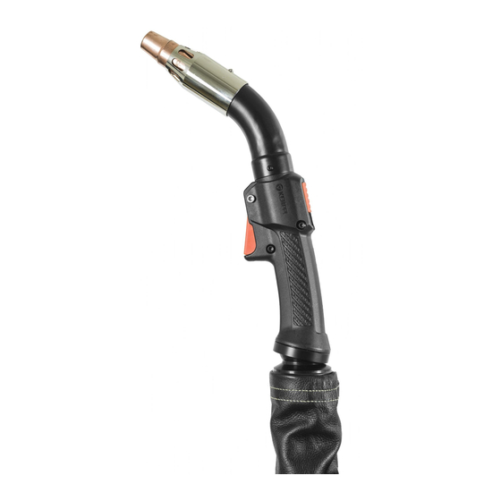
Flexlite GF Operating manual - EN 2. ABOUT EQUIPMENT The Flexlite GF MIG welding gun equipment consists of: The exact visual details may be different between different Flexlite GF models. Vacuum nozzle Gas nozzle Contact tip Contact tip adapter / gas diffuser... -
Page 5: Installation
Flexlite GF Operating manual - EN 3. INSTALLATION Ensure that the welding equipment is not connected to the mains or that the welding gun is not connected to the weld- ing machine until the installation is complete. Protect the equipment from rain and direct sunshine. -
Page 6: Assembling Gun
Flexlite GF Operating manual - EN 3.1 Assembling gun For component selection, refer to the product catalogue at Kemppi.com. Tools needed: Attach the contact tip adapter and hand-tighten it firmly in place. It is important to tighten the adapter properly to enable a tight connection of the contact tip to the gun. -
Page 7: Connecting Gun
Flexlite GF Operating manual - EN 3.2 Connecting gun Hand-tighten the gun connectors. Loose connectors may overheat, create contact disturbances, mechanical damage and water or gas leakage. For connecting the gun (and applicable extension parts), refer also to your welding equipment’s instructions. - Page 8 Flexlite GF Operating manual - EN Connect the gun's vacuum hose to the hose connected to the fume extraction unit. If necessary, secure the con- nection with tape. © Kemppi 1921590 / 2109...
-
Page 9: Installing And Replacing Wire Liner
If you change the filler wire to a different diameter or material, change also the feed rolls accordingly. With most of the Flexlite GF welding gun models both steel spiral wire liner and DL Chili wire liner can be used. - Page 10 Flexlite GF Operating manual - EN Feed the new wire liner into the cable hose until it stops at the gun neck end. Ensure that the contact tip adapter and contact tip are in place at this stage. Otherwise, depending on the welding gun model, the wire liner will go through without stopping.
- Page 11 Flexlite GF Operating manual - EN Insert the sleeve nut (delivered with the wire liner) without end cap and retainer cone on the wire liner and tighten it temporarily in place for measure. Cut the wire liner flush with the sleeve nut end.
- Page 12 Flexlite GF Operating manual - EN Don't leave any rough edges that could potentially damage the filler wire. Insert first the retainer cone and then the sleeve and end cap on the wire liner. Tighten the sleeve and end cap in place.
- Page 13 Flexlite GF Operating manual - EN Insert first the retainer cone and then the sleeve and end cap on the wire liner. Tighten the sleeve and end cap in place. © Kemppi 1921590 / 2109...
-
Page 14: Installing And Removing Grip Handle (Optional)
Operating manual - EN 3.4 Installing and removing grip handle (optional) The additional grip handle is available for all Flexlite GF MIG welding guns. Keeping the bottom of the grip handle pointing forward, fit the inside grooves of the grip handle over the screws on the gun. -
Page 15: Replacing And Adjusting Vacuum Nozzle
Flexlite GF Operating manual - EN 3.5 Replacing and adjusting vacuum nozzle The vacuum nozzle is a consumable part, which needs to be changed if worn. Remove the old vacuum nozzle by pressing the locking pin and pulling out the vacuum nozzle. -
Page 16: Replacing Vacuum Hose Cover
Operating manual - EN 3.6 Replacing vacuum hose cover The Flexlite GF welding gun's vacuum hose comes with a leather cover, attached with cable ties. Refer to this section when the vacuum hose leather cover needs to be replaced. The vacuum hose leather cover is a consumable part, which needs to be changed if worn. -
Page 17: Operation
With fume extraction on, hot fumes pass through the gun handle and affect the handle's temperature. To start welding, press the trigger switch. For component selection, refer to the product catalogue at Kemppi.com. © Kemppi 1921590 / 2109... -
Page 18: Measuring And Decreasing Fume Extraction Air Flow
Flexlite GF Operating manual - EN 4.1 Measuring and decreasing fume extraction air flow Fume extraction guns need to provide the appropriate amount of shielding gas to protect the weld from defects without compromising the fume capture efficiency of the gun. If the fume extraction air flow is too strong, it cap- tures shielding gas. -
Page 19: Optimizing Fume Extraction Efficiency
Operating manual - EN 4.2 Optimizing fume extraction efficiency The following factors help maximizing the fume extraction efficiency of a Flexlite GF welding gun. Welding positions and joint types The most effective position for fume extraction is the flat position (on the left) because the fumes naturally rise upward. - Page 20 Flexlite GF Operating manual - EN Removal of residual fumes At the end of welding, hold the fume extraction gun in place for 10 ... 15 seconds. This allows the gun to remove residual fumes as the weld is cooling.
-
Page 21: Maintenance
Use the correct tension torque when fastening loose parts. Do not use pressure washing devices. Service workshops Kemppi Service Workshops complete the welding system maintenance according to the Kemppi service agreement. The main aspects in the service workshop maintenance procedure are: •... -
Page 22: Troubleshooting
5.1 Troubleshooting The problems and the possible causes listed are not definitive, but suggest some typical situations that may turn up dur- ing normal use of the welding system. For further information and assistance, contact your nearest Kemppi service workshop. - Page 23 Flexlite GF Operating manual - EN • Make sure you are using original Kemppi consumable and spare parts. Incorrect spare part materials may cause the overheating of the neck. The welding gun connector overheats • Make sure the connector is properly connected to the wire feeder.
-
Page 24: Disposal Of Machine
The owner of the equipment is obliged to deliver a decommissioned unit to a regional collection center, as per the instructions of local authorities or a Kemppi representative. By applying these European Directives you improve the environment and human health. -
Page 25: Technical Data
Flexlite GF Operating manual - EN 6. TECHNICAL DATA "Technical data: Flexlite GF 300 A (gas-cooled)" on the next page "Technical data: Flexlite GF 300 A (water-cooled)" on page 28 "Technical data: Flexlite GF 400 A (gas-cooled)" on page 30 "Technical data: Flexlite GF 400 A (water-cooled)" on page 32 "Technical data: Flexlite GF 400 A Carsat (water-cooled)"... -
Page 26: Technical Data: Flexlite Gf 300 A (Gas-Cooled)
Flexlite GF Operating manual - EN 6.1 Technical data: Flexlite GF 300 A (gas-cooled) Flexlite GF 303G Feature Value Welding process MIG/MAG Contact tip M10x1 Method of guidance Manual Type of cooling Coolant flow rate (l/min) Coolant max. pressure (bar) Min. - Page 27 Flexlite GF Operating manual - EN Neck dimensions: Length x (mm) ( see figure below ) Height y (mm) ( see figure below ) Neck angle ɑ (°) ( see figure below ) Standards IEC 60974-7 ISO 21904-3 Gun length (m) 3.5 / 5...
-
Page 28: Technical Data: Flexlite Gf 300 A (Water-Cooled)
Flexlite GF Operating manual - EN 6.2 Technical data: Flexlite GF 300 A (water-cooled) Flexlite GF 303W Feature Value Welding process MIG/MAG Contact tip M10x1 Method of guidance Manual Type of cooling Liquid Coolant flow rate (l/min) Coolant max. pressure (bar) Min. - Page 29 Flexlite GF Operating manual - EN Neck dimensions: Length x (mm) ( see figure below ) Height y (mm) ( see figure below ) Neck angle ɑ (°) ( see figure below ) Standards IEC 60974-7 ISO 21904-3 Gun length (m) 3.5 / 5...
-
Page 30: Technical Data: Flexlite Gf 400 A (Gas-Cooled)
Flexlite GF Operating manual - EN 6.3 Technical data: Flexlite GF 400 A (gas-cooled) Flexlite GF 403G Feature Value Welding process MIG/MAG Contact tip M10x1 Method of guidance Manual Type of cooling Coolant flow rate (l/min) Coolant max. pressure (bar) Min. - Page 31 Flexlite GF Operating manual - EN Neck dimensions: Length x (mm) ( see figure below ) Height y (mm) ( see figure below ) Neck angle ɑ (°) ( see figure below ) Standards IEC 60974-7 ISO 21904-3 Gun length (m) 3.5 / 5...
-
Page 32: Technical Data: Flexlite Gf 400 A (Water-Cooled)
Flexlite GF Operating manual - EN 6.4 Technical data: Flexlite GF 400 A (water-cooled) Flexlite GF 403W Feature Value Welding process MIG/MAG Contact tip M10x1 Method of guidance Manual Type of cooling Liquid Coolant flow rate (l/min) Coolant max. pressure (bar) Min. - Page 33 Flexlite GF Operating manual - EN Neck dimensions: Length x (mm) ( see figure below ) Height y (mm) ( see figure below ) Neck angle ɑ (°) ( see figure below ) Standards IEC 60974-7 ISO 21904-3 Gun length (m) 3.5 / 5...
-
Page 34: Technical Data: Flexlite Gf 400 A Carsat (Water-Cooled)
Flexlite GF Operating manual - EN 6.5 Technical data: Flexlite GF 400 A Carsat (water-cooled) Flexlite GF 403WCS Feature Value Welding process MIG/MAG Contact tip M10x1 Method of guidance Manual Type of cooling Liquid Coolant flow rate (l/min) Coolant max. pressure (bar) Min. - Page 35 Flexlite GF Operating manual - EN Neck dimensions: Length x (mm) ( see figure below ) Height y (mm) ( see figure below ) Neck angle ɑ (°) ( see figure below ) Standards IEC 60974-7 ISO 21904-3 Gun length (m) * Measured using the longest gun length available.
-
Page 36: Ordering Codes
Tip: Letters with the product model names stand for: W = water-cooled, G = gas-cooled, CS = Carsat model. Flexlite GF Product Ordering code 3.5 m: 5 m: Flexlite GF 303G GF303G35 GF303G5 Flexlite GF 303W GF303W35 GF303W5 Flexlite GF 403G...
Need help?
Do you have a question about the Flexlite GF and is the answer not in the manual?
Questions and answers