Advertisement
Quick Links
DESCRIPTION
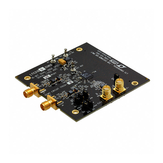
Demonstration circuit 1763A supports a family of 16-Bit
25Msps to 125Msps ADCs. Each assembly features one
of the following devices: LTC
LTC2192, LTC2191, LTC2190 high speed, dual ADCs.
The versions of the 1763A demo board are listed in Table 1.
Depending on the required resolution and sample rate,
the DC1763A is supplied with the appropriate ADC. The
Table 1. DC1763A Variants
DC1763A VARIANTS
1763A-A
1763A-B
1763A-C
1763A-D
1763A-E
1763A-F
PERFORMANCE SUMMARY
PARAMETER
Supply Voltage – DC1763A
Analog Input Range
Logic Input Voltages
Logic Output Voltages (Differential)
Sampling Frequency (Convert Clock Frequency)
Encode Clock Level
Resolution
Input Frequency Range
SFDR
SNR
16-Bit, 25Msps to 125Msps Dual ADCs
®
2195, LTC2194, LTC2193,
ADC PART NUMBER
LTC2195
LTC2194
LTC2193
LTC2192
LTC2191
LTC2190
(T
= 25°C)
A
CONDITIONS
Depending on Sampling Rate and the A/D Converter
Provided, this Supply Must Provide up to 500mA.
Depending on SENSE Pin Voltage
Minimum Logic High
Maximum Logic Low
Nominal Logic Levels (100Ω Load, 3.5mA Mode)
Common Mode
Minimum Logic Levels (100Ω Load, 3.5mA Mode)
Common Mode
See Table 1
Single-Ended Encode Mode (ENC
Differential Encode Mode (ENC
See Table 1
See Table 1
See Applicable Data Sheet
See Applicable Data Sheet
DEMO MANUAL DC1763A
LTC2195, LTC2194, LTC2193,
LTC2192, LTC2191, LTC2190
circuitry on the analog inputs is optimized for analog input
frequencies from 5MHz to 140MHz. Refer to the data sheet
for proper input networks for different input frequencies.
Design files for this circuit board are available at
http://www.linear.com/demo
L, LT, LTC, LTM, μModule, Linear Technology and the Linear logo are registered trademarks
and PScope is a trademark of Linear Technology Corporation. All other trademarks are the
property of their respective owners.
RESOLUTION
MAXIMUM SAMPLE RATE
16-Bit
16-Bit
16-Bit
16-Bit
16-Bit
16-Bit
–
Tied to GND)
–
Not Tied to GND)
INPUT FREQUENCY
125Msps
5MHz to 140MHz
105Msps
5MHz to 140MHz
80Msps
5MHz to 140MHz
65Msps
5MHz to 140MHz
40Msps
5MHz to 140MHz
25Msps
5MHz to 140MHz
MIN
TYP
3
3.6
1
1.3
0.6
350
1.25
247
1.25
0
0.2
MAX
UNITS
6
V
2
V
P-P
V
V
mV
V
mV
V
3.6
V
3.6
V
dc1763af
1
Advertisement

Related Manuals for Linear Technology DC1763A-F


Summary of Contents for Linear Technology DC1763A-F
- Page 1 Depending on the required resolution and sample rate, L, LT, LTC, LTM, μModule, Linear Technology and the Linear logo are registered trademarks and PScope is a trademark of Linear Technology Corporation. All other trademarks are the the DC1763A is supplied with the appropriate ADC. The property of their respective owners.
-
Page 2: Quick Start Procedure
DEMO MANUAL DC1763A QUICK START PROCEDURE Demonstration circuit 1763A is easy to set up to evaluate Optional Jumpers: the performance of the LTC2195 A/D converter family. Refer J8 Term: Enables/Disables optional output termination. to Figure 1 for proper measurement equipment setup and (default: removed) follow the procedure below: J5 ILVDS: Selects either 1.75mA or 3.5mA of output... - Page 3 The DC1763A should not be removed, or connected to using a sinusoidal signal generator a squaring circuit can the DC1371 while power is applied. be used. Linear Technology also provides demo board DC1075 that divides a high frequency sine wave by four, Analog Input Network...
- Page 4 DEMO MANUAL DC1763A QUICK START PROCEDURE If the DC1763A demonstration circuit is properly connected to the DC1371, PScope should automatically detect the DC1763A, and configure itself accordingly. If everything is hooked up properly, powered and a suitable convert clock is present, clicking the Collect button should result in time and frequency plots displayed in the PScope window.
- Page 5 DEMO MANUAL DC1763A QUICK START PROCEDURE Channel 1 Nap: Selects between normal operation and Internal Termination: Enables LVDS internal termination putting channel 1 in nap mode. • Off (Default): Disables internal termination • Off (Default): Channel one is active • On: Enables internal termination •...
-
Page 6: Parts List
DEMO MANUAL DC1763A PARTS LIST ITEM REFERENCE PART DESCRIPTION MANUFACTURER/PART NUMBER Required Circuit Components Capacitor, Array, 0508, 2.2μF , 20%, 4V, X5R AVX, W2L14D225MAT1A C2, C3, C5, C7, C8, C9, C15, C16, C18, Capacitor, X5R, 0.1μF , 10V, 10%, 0402 AVX, 0402ZD104KAT2A C28, C36, C48, C52 Capacitor, X5R, 1μF , 10V, 10%, 0402... - Page 7 Transformer, RF~SMT~1:1 Balun Macom, MABA-007159-000000 T8, T10 Transformer, Flux-Coupled Balun Macom, MABAES0060 IC, LT1763CS8-1.8 SO8 Linear Technology, LT1763CS8-1.8#PBF IC, EEPROM 32KBIT 400khz 8TSSOP Microchip, 24LC32A-I/ST XJ2, XJ5, XJ8, XJ13, XJ14, XJ15 Shunt, 0.079" Center Samtec, 2SN-BK-G Stencil (Top & Bottom)
-
Page 8: Schematic Diagram
DEMO MANUAL DC1763A SCHEMATIC DIAGRAM dc1763af... - Page 9 Information furnished by Linear Technology Corporation is believed to be accurate and reliable. However, no responsibility is assumed for its use. Linear Technology Corporation makes no representa- tion that the interconnection of its circuits as described herein will not infringe on existing patent rights.
- Page 10 Linear Technology Corporation (LTC) provides the enclosed product(s) under the following AS IS conditions: This demonstration board (DEMO BOARD) kit being sold or provided by Linear Technology is intended for use for ENGINEERING DEVELOPMENT OR EVALUATION PURPOSES ONLY and is not provided by LTC for commercial use. As such, the DEMO BOARD herein may not be complete in terms of required design-, marketing-, and/or manufacturing-related protective considerations, including but not limited to product safety measures typically found in finished commercial goods.
Need help?
Do you have a question about the DC1763A-F and is the answer not in the manual?
Questions and answers