Advertisement
Description
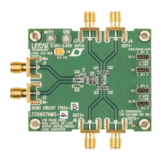
Demonstration Circuit 1765A features the
LTC6957-2, a low phase noise, dual LVPECL or LVDS
output buffer/driver/logic converter.
The DC1765A provides 0.5" spaced SMA connectors for
the differential inputs and outputs. The inputs are termi-
nated to on-board 50Ω resistors. The LVPECL outputs
of the DC1765A-A are individually biased through 130Ω
resistors to ground and then AC-coupled. The transmis-
sion lines are 50Ω, making the outputs suitable to drive
50Ω input impedance instruments. The LVDS outputs
of the DC1765A-B are terminated with 100Ω differential
Low Phase Noise, Dual LVPECL or LVDS
Output Buffer/Driver/Logic Converter
LTC
6957-1/
®
Figure 1. DC1765A Inputs and Outputs
DEMO MANUAL DC1765A
LTC6957-1/LTC6957-2
and are DC-coupled. The DC1765A allows the user to
take advantage of the shutdown and bandwidth selection
features of the LTC6957. The DC1765A can operate with
a single-ended or differential sine wave or square-wave
input signal. Supply the DC1765A with 3.3V and it is
ready to function. The DC1765A offers extra component
population options to make it compatible with different
logic signal types.
Design files for this circuit board are available at
http://www.linear.com/demo
L, LT, LTC, LTM, Linear Technology and the Linear logo are registered trademarks of Linear
Technology Corporation. All other trademarks are the property of their respective owners.
dc1765af
1
Advertisement
Table of Contents

Related Manuals for Linear Technology DC1765A


Summary of Contents for Linear Technology DC1765A
- Page 1 DC1765A-B are terminated with 100Ω differential L, LT, LTC, LTM, Linear Technology and the Linear logo are registered trademarks of Linear Technology Corporation. All other trademarks are the property of their respective owners. Figure 1. DC1765A Inputs and Outputs...
-
Page 2: Quick Start Procedure
The DC1765A is very straightforward to operate. Refer to DC1765A Reconfiguration Figure 1 for the following discussion. The DC1765A is flexible and allows the connectivity of a variety of input and output signal types. The DC1765A is DC1765A Configuration configured as shown in the schematic diagram. However, 1. -
Page 3: Assembly Options
Table 1. DC1765A Assembly Options ASSEMBLY VERSION PART NUMBER OUTPUT TYPE DC1765A-A LTC6957HMS-1 LVPECL DC1765A-B LTC6957HMS-2 LVDS layout top layer The top metal layer of the DC1765A is shown here as an example of good PCB layout for the LTC6957-1/LTC6957-2. dc1765af... -
Page 4: Parts List
DEMO MANUAL DC1765A parts list ITEM REFERENCE PART DESCRIPTION MANUFACTURER/PART NUMBER DC1765A General BOM C6, C8 CAP., X7R, 0.01µF 50V 10%, 0603 NIC, NMC0603X7R103K50TRP CAP., X7R, 0.1µF 50V 10%, 0603 TDK, C1608X7R1H104K CAP., X5R, 1µF 25V 10%, 0603 TDK, C1608X5R1E105K CAP., TANT, 22µF 10V, 3528... -
Page 5: Schematic Diagram
Information furnished by Linear Technology Corporation is believed to be accurate and reliable. However, no responsibility is assumed for its use. Linear Technology Corporation makes no representa- tion that the interconnection of its circuits as described herein will not infringe on existing patent rights. - Page 6 Linear Technology Corporation (LTC) provides the enclosed product(s) under the following AS IS conditions: This demonstration board (DEMO BOARD) kit being sold or provided by Linear Technology is intended for use for ENGINEERING DEVELOPMENT OR EVALUATION PURPOSES ONLY and is not provided by LTC for commercial use. As such, the DEMO BOARD herein may not be complete in terms of required design-, marketing-, and/or manufacturing-related protective considerations, including but not limited to product safety measures typically found in finished commercial goods.
Need help?
Do you have a question about the DC1765A and is the answer not in the manual?
Questions and answers