Advertisement
Quick Links
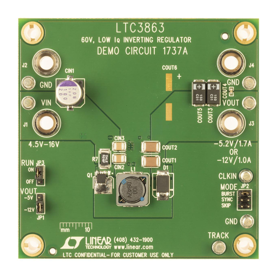
DESCRIPTION
Demonstration circuit 1737A is a current-mode inverting
DC/DC converter featuring the
The board operates from an input range of 4.5V to 16V,
and provides a –5.2V, 1.7A output or a –12V, 1A output
(jumper selectable). It operates at 400kHz and may be
synchronized to an external clock. A soft-start feature
controls output voltage slew rate at start-up, reducing
current surge and voltage overshoot. Burst Mode
tion that improves efficiency at light loads can be enabled
with a jumper. A power good output signal is provided.
The demonstration board has options for larger MOSFET
and diode packages on the back of the board for higher
output current requirements.
PERFORMANCE SUMMARY
SYMBOL
PARAMETER
V
Input Supply Range
IN
V
Output Voltage
OUT
I
Output Current Range, Continuous
OUT
f
Switching (Clock) Frequency
SW
V
Output Ripple
OUT P-P
V
Output Regulation
REG
P
/P
Efficiency (See Figure 3)
OUT
IN
Approximate Size
LTC
3863.
®
opera-
®
Specifications are at T
CONDITIONS
Free Air
V
= 12V, V
= –12V, I
IN
OUT
Line and Load (4.5V
V
= 12V, V
= –12V, I
IN
OUT
Component Area × Top Component Height
DEMO MANUAL DC1737A
DC/DC Converter
This board is suitable for a wide range of automotive,
telecom, industrial, and other applications. The LTC3863
is available in small 12-pin thermally enhanced MSOP and
DFN Packages. For other output requirements, see the
LTC3863 data sheet or contact the LTC factory.
Design files for this circuit board are available at
http://www.linear.com/demo
L, LT, LTC, LTM, Linear Technology, the Linear logo and Burst Mode are registered trademarks
of Linear Technology Corporation. All other trademarks are the property of their respective
owners.
= 25°C
A
= 1A (20MHz BW)
OUT
to 16V
, –12V
, 0A to 1A Out)
IN
IN
OUT
= 1A
OUT
LTC3863
Low I
Inverting
Q
MIN
TYP
MAX
4.5
16
–5.2V/–12V
0
–1.7/1.0
400
30
±0.1
89.3
0.9 × 0.8 × 0.18
UNITS
V
V
A
kHz
mV
P-P
%
%
Inches
dc1737af
1
Advertisement

Related Manuals for Linear Technology DC1737A


Summary of Contents for Linear Technology DC1737A
- Page 1 ® L, LT, LTC, LTM, Linear Technology, the Linear logo and Burst Mode are registered trademarks tion that improves efficiency at light loads can be enabled of Linear Technology Corporation. All other trademarks are the property of their respective owners.
- Page 2 DC1737A’s input current. Note: When measuring the output voltage ripple, care must c. A voltmeter with a capability of measuring at least...
-
Page 3: Quick Start Procedure
DC can be put in series with the output load in order age, efficiency and other desired parameters. to measure the DC1737A’s output current. 8. Remove the VOUT jumper to observe operation at b. A voltmeter with a capability of measuring at least 12V –12V... -
Page 4: Parts List
DEMO MANUAL DC1737A PARTS LIST ITEM REFERENCE PART DESCRIPTION MANUFACTURER/PART NUMBER Required Circuit Components CIN1 Cap., SMT, 100µF, 20V, SVP OSCON SANYO, 20SVP100M CIN2, CIN3 CAP.,X7R, 10µF, 25V, 20%, 1210 TDK, C3225X7R1E106M COUT1, COUT2 CAP.,X7R, 33µF, 16V, 20%, 1812 TDK, C4532X7R1C336M COUT3, COUT5 CAP.,POSCAP, 150µF, 16V 7343... -
Page 5: Schematic Diagram
Information furnished by Linear Technology Corporation is believed to be accurate and reliable. However, no responsibility is assumed for its use. Linear Technology Corporation makes no representa- tion that the interconnection of its circuits as described herein will not infringe on existing patent rights. - Page 6 Linear Technology Corporation (LTC) provides the enclosed product(s) under the following AS IS conditions: This demonstration board (DEMO BOARD) kit being sold or provided by Linear Technology is intended for use for ENGINEERING DEVELOPMENT OR EVALUATION PURPOSES ONLY and is not provided by LTC for commercial use. As such, the DEMO BOARD herein may not be complete in terms of required design-, marketing-, and/or manufacturing-related protective considerations, including but not limited to product safety measures typically found in finished commercial goods.
- Page 7 Mouser Electronics Authorized Distributor Click to View Pricing, Inventory, Delivery & Lifecycle Information: Analog Devices Inc. DC1737A...
Need help?
Do you have a question about the DC1737A and is the answer not in the manual?
Questions and answers