Advertisement
Quick Links
Advertisement

Related Manuals for CLIVET Q4DN-2-XMi Series


Summary of Contents for CLIVET Q4DN-2-XMi Series
- Page 1 4-WAY CASSETTE Q4DN-2-XMi series D28÷D140 M0VY00002-01 - 12/2020...
- Page 2 MUST NOT be performed. WARRANTY The product CLIVET is covered by a conventional warranty, valid from the date of purchase of the appliance, the conditions of which are specified in the GENERAL CONDITIONS OF SALE available at www.clivet.com WARNING –...
- Page 3 INDEX General Details ..........4 6 Use ..............32 General warnings and safety rules 6.1 Description of system components 1.2 Description of system components 6.2 Operation 1.3 Accessories 6.2.1 Meaning of the display codes 1.4 Identification 6.3 Other functions 6.4 Airflow angle control 2 Installation ............
- Page 4 WARNING – This manual is the property of CLIVET and reproduction or transfer to third parties of the contents of this document is prohibited. All rights reserved. It is an integral part of the product; make sure that it is always supplied with the appliance, even in case of sale/transfer to another owner, so that it can be consulted by the user or by personnel authorised to carry out maintenance and repairs.
- Page 5 General Details – Always use the specified cables for all electrical work. Connect the cables securely and secure them in a stable manner to prevent the terminals from being damaged by external forces. Incorrect electrical connection may cause overheating conditions and may result in fire and electrocution. –...
- Page 6 General Details CAUTION DANGER – When connecting refrigerant piping,keep substances or gases other than the specified refrigerant from entering the unit. The presence of other gases or substances can reduce unit performance and cause an abnormal increase in pressure in the refrigeration cycle. This can lead to explosion hazards and resulting injuries. –...
- Page 7 General Details IT IS PROHIBITED TO – Make changes and/or repair attempts to the product. Any repairs must be carried out by a qualified technician. – Touch the appliance with wet, damp and/or barefoot body parts. If you notice current leakage that can be detected on contact with metal parts of the appliance, disconnect the switch, unplug it from the power supply socket and contact an authorised dealer.
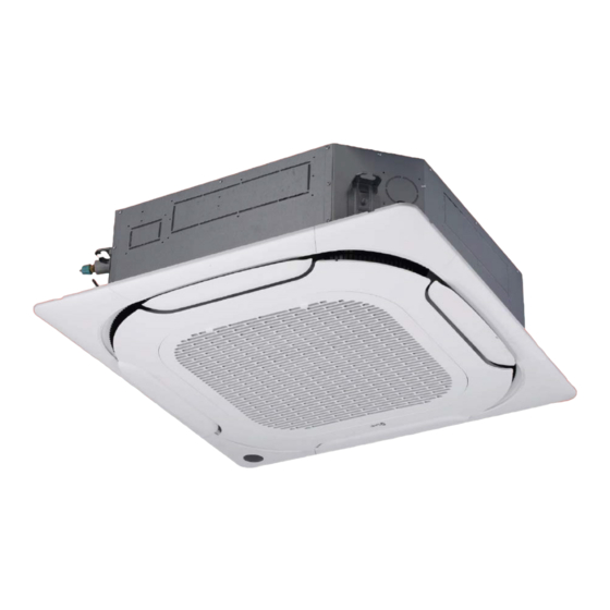
- Page 8 General Details Description of system components Fig. 1 1 Ventilation louver 4 Air outlet 2 Display LED 5 Air inlet 3 Front grille WARNING The images in this manual are provided for illustrative purposes only. The appearance of your appliance may differ slightly from the illustrations shown here.
- Page 9 General Details Accessories Identification The air conditioning system is provided with the following The indoor unit can be identified by the serial number accessories. Use all specified installation components label that shows the technical and performance data of the and accessories to install it. appliance and what is required by the legislation in force.
- Page 10 Installation 2 INSTALLATION Installation - preliminary warnings WARNING Product receiving Before installing the indoor unit, consult the The appliance is supplied packed in several parcels. label on the product package to check that the Handling must be carried out by appropriate means in model number matches the model number of view of the overall weight of the package.
- Page 11 Installation Installation ATTENTION ELECTRIC DANGER – All electrical connections must be done by a 2.4.1 Installation room licensed electrician according to the provisions of national and local electrical codes. CAUTION – All electrical connections must be made The appliance must be placed in a well- according to the wiring diagram on the ventilated room, with a minimum surface panels of the indoor and outdoor units.
- Page 12 Installation It is PROHIBITED to install the indoor It is PROHIBITED to install the indoor unit in the following locations: unit in the following locations: – in a bathroom or laundry room, because – oil extraction drilling or fracking areas; excess humidity can reduce its service life –...
- Page 13 Installation Connect to the water pipe outlet Connect to the refrigerant pipes (gas) Connect to the refrigerant pipes (liquid) Ceiling Panel Air outlet Air outlet Air inlet 910 mm (ceiling hole) Floor Fig. 4 Model A (mm) H (mm) ≤ 8.0 kW ≤...
- Page 14 Installation 2.4.2 Hang the indoor unit Size: Ø75 mm air inlet Rear view Side view Ø32 mm (outer diameter of water drainage pipe) Refrigerant pipe vent (liquid side “C”) Refrigerant pipe vent (gas side “D”) Model (mm) (mm) (mm) (mm) 2.8-4.5 kW Ø...
- Page 15 Installation 3 Reinforce the ceiling where necessary to stop it from sagging. Anchor rod 4 Determine the length and direction of the pipes to be installed and the wiring. Hexagonal 5 After choosing the installation position, put the refrigerant piping, the drainage pipes and the internal and external electrical lines in their respective Ceiling Panel...
- Page 16 Installation – Existing concrete slab 10 Assemble the indoor unit. Two people are needed Install the suspension hook with expansion anchor to lift and fasten the unit. Insert the anchor rods into 45~50 mm deep in the concrete to prevent it from the unit’s attachment holes.
- Page 17 Installation 2.4.3 Derived ducts These units can be fitted with small ducts for air Water level conditioning a small room nearby. The units are designed for ducting on 3 sides: the side with the electronic expansion valve cannot be ducted. Distribution duct Fig.
- Page 18 Installation – If two air ducts are connected: CAUTION for 5.6~8.0 kW models, the volume of air in the The drain pipe outlet must be at least 5 cm duct is about 200~260 m from the floor. If it touches the ground, the unit for 9.0~14.0 kW models, the volume of air in the can block and not work properly.
- Page 19 Installation every 0.8~1 metres to prevent the water drain pipes from bending. See “Fig. 23”. 800 ~ 5 When connecting long water drain pipe, 1000mm the connections must be covered with insulation to prevent them from coming loose. 6 When the water drain pipe outlet is higher than the water intake pipe connection, try to keep the drain pipe as vertical as possible;...
- Page 20 Installation CAUTION DANGER WARNING – The drain cap at the base of the unit’s casing is – When using an extension for the drainage used to drain the water accumulated in the drain pipe, tighten the connection on the inside pan should the air conditioner malfunction.
- Page 21 Electrical connections 3 ELECTRICAL CONNECTIONS Preliminary information ATTENTION ELECTRIC DANGER – All electrical connections must be done by a licensed electrician according to the provisions of national and local electrical codes. – Only use copper cables. – Air conditioners must use a dedicated power supply socket.
- Page 22 Electrical connections Power cable connection If the insulated ring terminal cannot be used, make sure you: – Do not connect two power cables with different Use a dedicated power supply to the indoor unit that is diameters to the same terminal (this can cause the different from that to the outdoor unit.
- Page 23 Electrical connections Refer to the tables below for power cable specifications. Communication wiring Electrical characteristics of indoor units – Only use shielded cables for communication wiring. Any other type of cable can produce interference Power supply Capacity between signals, causing the units to malfunction. Volts MCA 2.8 kW 0.41...
-
Page 24: Table Of Contents
Electrical connections 3.3.1 Communication wiring between the 3.3.2 Communication wiring between the indoor and outdoor units indoor unit and the wired controller The wired controller and the indoor unit can be – The indoor and outdoor units communicate via the connected in different ways, depending on the forms of RS485 serial port. -
Page 25: Fig. 34
Electrical connections 2 For a one-way communication mode – Once the wiring has been laid and the connections have been made, fasten and secure the wiring – Use 1 wired controller to control 1 indoor unit properly to prevent an external force from pulling (See “Fig. -
Page 26: Fig. 36
Electrical connections Assembling the panel IT IS PROHIBITED TO – place the panel face down on the floor, against a wall or on an uneven surface. – hit or crush the deflector. 1 Remove the air intake grille. – Push the two tongues towards the centre at the same time to unlock the grille catch Fig. - Page 27 Electrical connections – Position and secure the panel on the main unit body with M6 bolts and washers. Ensure that the motors are embedded in the housing provided. – Tighten the screws of the panel hooks in the four corners equally. CAUTION Tighten the screws until the thickness of the spongy material between the main body and...
- Page 28 Electrical connections – Fasten the door. Bolt Cable Self-tapping screw Fig. 45 A Unit body – Slide hooks into the slots B Panel C Main unit body side connector D Panel side connector E Protective sheath F Connector G Cable ties Fig.
- Page 29 Configuration 4 CONFIGURATION WARNING The power DIP switches have been configured Power setting before delivery. These settings must only be changed by qualified maintenance personnel. Set the board’s DIP switch on the internal electrical panel for different applications. Once it has been set, disconnect the main power switch and then reconnect it.
- Page 30 Configuration DIP Switch settings on main board In heating mode, the fan does not operate when the temperature midpoint of the SW1_1 internal heat exchanger is 20°C or lower. [01] Cooling mode temperature compensation: In heating mode, the fan does not operate 0°C when the temperature midpoint of the [0_]...
- Page 31 Running the test 5 RUNNING THE TEST Checks to perform before running the test – Indoor and outdoor units properly installed; – Correct pipes and wiring; – No seepage from the refrigerant piping system; – Correct water drain; – Full insulation; –...
- Page 32 6 USE WARNING – DO NOT touch the air outlet while the flaps Description of system components are swinging. Fingers can get trapped or the unit can break down. – To prevent the appliance from deteriorating, do not use the air conditioner for preservation purposes (food, plants, animals, works of art, etc.).
- Page 33 Operation 6.2.1 Meaning of the display codes Display Description Operation indicator: during normal operation the light is on. If the unit is in stand-by, the light flashes. The light turns on if a timer has been set. The light turns on if the defrosting function is activated.
- Page 34 Airflow angle control As hot air rises and cold air falls, the distribution of heated/cooled air in a closed room can be improved by positioning the unit’s louvers. The angle of the louvers can be adjusted by pressing the [SWING] button on the remote control. WARNING –...
- Page 35 Maintenance 7 MAINTENANCE Cleaning the air filter The filter stops dust and other particles from entering the It is good practice to periodically clean both the internal indoor unit. A build-up of dust can reduce the efficiency and external parts of the appliance. This guarantees its of the air conditioner.
- Page 36 Maintenance Extended periods of inactivity If you do not plan to use the air conditioner for an extended period of time, proceed as follows: Fig. 53 Clean all filters Activate the Ventilation mode until the unit is completely 4 Remove the air filter. dry (at least 12 hours) 5 Clean the air filter with a vacuum cleaner or wash it with warm water and a mild detergent.
- Page 37 Maintenance Troubleshooting CAUTION DANGER If any of the following conditions occur, switch the unit off immediately. – The power cable is damaged or unusually hot. – You can smell burning. – The unit makes loud or abnormal noises. – A fuse blows or the circuit breaker trips frequently. –...
- Page 38 Maintenance 7.5.2 Anomalies and remedies If problems occur, please check the following before contacting a service centre. Anomalies Possible causes Remedies The set temperature may be higher than Set a lower temperature the room temperature The heat exchanger of the indoor or Clean the heat exchanger (Service Centre) outdoor unit is dirty Remove the filter and clean it following...
- Page 39 Maintenance Indoor unit error codes Error code Description Possible causes – The operating mode of the indoor unit clashes Mode conflict with that of the outdoor units. – Communication cables between indoor and outdoor units are not connected properly. – Interference from high voltage wires or other Communication error between indoor and sources of electromagnetic radiation.
- Page 40 Disposal 8 DISPOSAL The manufacturer is registered on the National EEE Professional WEEE: all WEEE which comes from Register, in compliance with implementation of Directive something other than private households. 2012/19/EU and pertinent national regulations on electrical This equipment may contain: and electronic equipment waste.
- Page 41 Attachments 9 ATTACHMENTS Indoor unit wiring diagrams...
- Page 42 Disposal...
- Page 43 EGALE APPRESENTANTE CLIVET S.P.A. - Via Camp Lonc, 25 - Z.I. VILLAPAIERA - 32030 FELTRE (BL) – ITALIA Cap. Soc. Eur 20.000.000 i.v. – C.F. e reg.Impr. BL n°.00708410253 – R.E.A. n°.66577 –P.I./ VAT :IT 00708410253 Tel. +39 0439 3131 - Fax +39 0439 313300 – Sito Web : www.clivet.it...
- Page 44 FOR 30 YEARS WE HAVE BEEN OFFERING SOLUTIONS FOR SUSTAINABLE COMFORT AND THE WELL-BEING OF PEOPLE AND THE ENVIRONMENT www.clivet.com sales and service CLIVET SPA Via Camp Lonc 25, Z.I. Villapaiera 32032 Feltre (BL) - Italy Tel. +39 0439 3131 - Fax +39 0439 313300 info@clivet.it...
Need help?
Do you have a question about the Q4DN-2-XMi Series and is the answer not in the manual?
Questions and answers