Table of Contents
Advertisement
Advertisement
Table of Contents

Subscribe to Our Youtube Channel
Related Manuals for CLIVET Q4AN-2-XMi Series


Summary of Contents for CLIVET Q4AN-2-XMi Series
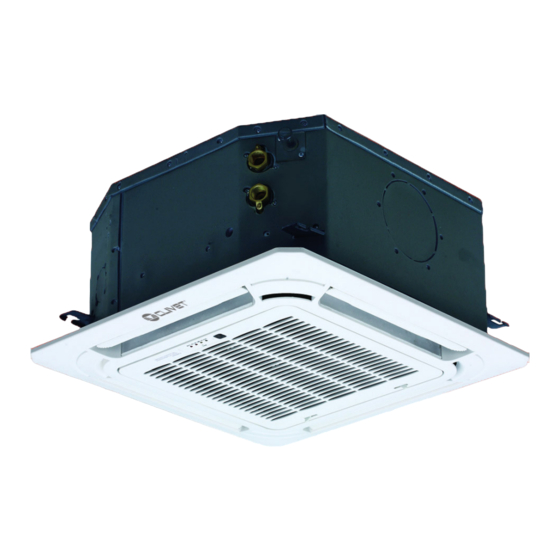
- Page 1 COMPACT 4-WAY CASSETTE Q4AN-2-XMi series D17÷D52 M0VX00002-02 - 04/2021...
- Page 2 MUST NOT be performed. WARRANTY The product CLIVET is covered by a conventional warranty, valid from the date of purchase of the appliance, the conditions of which are specified in the GENERAL CONDITIONS OF SALE available at www.clivet.com WARNING –...
- Page 3 INDEX General Details ..........4 6 Use ..............31 General warnings and safety rules 6.1 Description of system components 1.2 Description of system components 6.2 Operation 1.3 Accessories 6.2.1 Meaning of the display codes 1.4 Identification 6.3 Other functions 6.4 Airflow angle control 2 Installation ............
-
Page 4: General Details
WARNING – This manual is the property of CLIVET and reproduction or transfer to third parties of the contents of this document is prohibited. All rights reserved. It is an integral part of the product; make sure that it is always supplied with the appliance, even in case of sale/transfer to another owner, so that it can be consulted by the user or by personnel authorised to carry out maintenance and repairs. - Page 5 General Details – Always use the specified cables for all electrical work. Connect the cables securely and secure them in a stable manner to prevent the terminals from being damaged by external forces. Incorrect electrical connection may cause overheating conditions and may result in fire and electrocution. –...
- Page 6 General Details CAUTION DANGER – When connecting refrigerant piping,keep substances or gases other than the specified refrigerant from entering the unit. The presence of other gases or substances can reduce unit performance and cause an abnormal increase in pressure in the refrigeration cycle. This can lead to explosion hazards and resulting injuries. –...
- Page 7 General Details IT IS PROHIBITED TO – Make changes and/or repair attempts to the product. Any repairs must be carried out by a qualified technician. – Touch the appliance with wet, damp and/or barefoot body parts. If you notice current leakage that can be detected on contact with metal parts of the appliance, disconnect the switch, unplug it from the power supply socket and contact an authorised dealer.
-
Page 8: Description Of System Components
General Details Description of system components Fig. 1 1 Ventilation louver 4 Air outlet 2 Display LED 5 Air inlet 3 Front grille WARNING The images in this manual are provided for illustrative purposes only. The appearance of your appliance may differ slightly from the illustrations shown here. - Page 9 General Details Accessories Identification The air conditioning system is provided with the following The indoor unit can be identified by the serial number accessories. Use all specified installation components label that shows the technical and performance data of the and accessories to install it. appliance and what is required by the legislation in force.
-
Page 10: Installation
Installation 2 INSTALLATION Installation - preliminary warnings WARNING Product receiving Before installing the indoor unit, consult the label on the product package to check that the The appliance is supplied packed in several parcels. model number matches the model number of Handling must be carried out by appropriate means in the outdoor unit. -
Page 11: Installation Room
Installation Installation ATTENTION ELECTRIC DANGER – All electrical connections must be done by a 2.4.1 Installation room licensed electrician according to the provisions of national and local electrical codes. CAUTION – All electrical connections must be made The appliance must be placed in a well-ventilated according to the wiring diagram on the room, with a minimum surface area that varies panels of the indoor and outdoor units. - Page 12 Installation It is PROHIBITED to install the indoor It is PROHIBITED to install the indoor unit in the following locations: unit in the following locations: – in a bathroom or laundry room, because – oil extraction drilling or fracking areas; excess humidity can reduce its service life –...
- Page 13 Installation Electrical panel Ceiling Air outlet Air outlet Air inlet Floor Fig. 4 Based on the layout of the installation room, determine the direction of air flow. See “Fig. 5” for the air flow direction diagram. To lockout the air flow, a deflector must be inserted into the unit’s casing. Unit body Air deflector Fig.
- Page 14 Installation 2.4.2 Hang the indoor unit Size: 647 (Panel) 647 (Panel) 570 (Body) 570 (Body) 545 (Hook-location) 545 (Position of rods) Drainage side Drainage side Drainage pipe Drainage pipe Hook Gas pipe Gas pipe Body Body Refrigerant Liquid pipe pipe Panel Panel L=30~40...
- Page 15 Installation 1 Using the paper template provided, make a 640mm x – New concrete slab 640mm hole in the ceiling. Embed the anchor rods. 2 The midpoint of the ceiling opening must correspond to the centre of the indoor unit’s casing. Ceiling (Insert with wings) (Sliding insert)
- Page 16 Installation 8 Install the four anchor rods (M10). Wall 9 Determine the length of the rods based on the height of the ceiling. Remove the surplus part. 10-12mm False ceiling Main body Fig. 15 CAUTION DANGER Check that the unit is completely horizontal. Incorrect installation can cause the drain pipe to go back into the unit or possible water leaks.
- Page 17 Installation NOTE FOR INSTALLATION IN NEW BUILDS 2.4.3 Preparation for connection pipes It is necessary to make a hole in the wall where the refrigerant Main body piping, drainage pipe and electrical cables that will connect the indoor unit to the outdoor unit will pass through. 1 Determine hole position in the wall according to the position of the outdoor unit.
-
Page 18: Drainage Pipe
Installation 2.4.4 Drainage pipe The drainage pipe is used to drain the water from the 800 ~ unit. Incorrect installation can cause damage to the unit 1000mm and other material damage. CAUTION DANGER – Insulate all of the pipes to prevent condensate from forming, which could cause water damage. - Page 19 Installation Water drain pipes from multiple units are connected to the main drain pipe that flows into the waste water pipes. < 200 mm 50~100mm < 200 mm 50~100mm 50~100mm < 200 mm < 600 mm A Water drain pipe fittings C 1/100 slope or more B Main water drain pipe Fig.
-
Page 20: Electrical Connections
Electrical connections 3 ELECTRICAL CONNECTIONS Preliminary information ATTENTION ELECTRIC DANGER – All electrical connections must be done by a licensed electrician according to the provisions of national and local electrical codes. – Only use copper cables. – Air conditioners must use a dedicated power supply socket. -
Page 21: Power Cable Connection
Electrical connections Power cable connection If the insulated ring terminal cannot be used, make sure you: – Do not connect two power cables with different Use a dedicated power supply to the indoor unit that is diameters to the same terminal (this can cause the different from that to the outdoor unit. -
Page 22: Communication Wiring
Electrical connections Refer to the tables below for power cable specifications. Communication wiring Electrical characteristics of indoor units – Only use shielded cables for communication wiring. Any other type of cable can produce interference Power supply Capacity between signals, causing the units to malfunction. Volts MCA 1.7 kW 0.42... - Page 23 Electrical connections 3.3.1 Communication wiring between the 3.3.2 Communication wiring between the indoor and outdoor units indoor unit and the wired controller The wired controller and the indoor unit can be connected in – The indoor and outdoor units communicate via the different ways, depending on the forms of communication.
- Page 24 Electrical connections 2 For a one-way communication mode – Once the wiring has been laid and the connections have been made, fasten and secure the wiring – Use 1 wired controller to control 1 indoor unit properly to prevent an external force from pulling (See “Fig.
-
Page 25: Assembling The Panel
Electrical connections Assembling the panel IT IS PROHIBITED TO place the panel face down on the floor, against a wall or on an uneven surface. 1 Remove the air intake grille. – Push the two tongues towards the centre at the same time to unlock the grille catch Fig. - Page 26 Electrical connections Unscrew the top nut Space not allowed A Panel 3 sealing foam G Ceiling B Panel H Panel 2 sealing foam Adjust the C Foam panel 1 Body bottom nut D Air inlet Entering air Fig. 35 E Foam panel 2 M Leaving air F Panel 1 sealing foam –...
-
Page 27: Power Setting
Configuration 4 CONFIGURATION WARNING The power DIP switches have been configured Power setting before delivery. These settings must only be changed by qualified maintenance personnel. Set the board’s DIP switch on the internal electrical panel for different applications. Once it has been set, disconnect the main power switch and then reconnect it. - Page 28 Configuration DIP Switch settings on main board When the set temperature is reached SW1_1 in heating mode, the fan operates on a 4-minute off / 1-minute on cycle. [00] Cooling mode temperature compensation: 0°C When the set temperature is reached in [0_] heating mode, the fan operates on an 8-minute off / 1-minute on cycle.
- Page 29 Configuration Automatic restart function enabled Automatic restart function enabled SW7_1 Reserved [0_] SW7_2 Unit with 2.2 to 5.2 kW capacity [_0] Unit with 1.7 kW capacity [_1] CAUTION All DIP switches (including power DIP switches) have been configured before delivery. These settings should only be changed by qualified maintenance personnel.
-
Page 30: Running The Test
Running the test 5 RUNNING THE TEST Checks to perform before running the test – Indoor and outdoor units properly installed; – Correct pipes and wiring; – No seepage from the refrigerant piping system; – Correct water drain; – Full insulation; –... - Page 31 6 USE CAUTION DANGER – If an abnormal condition occurs (e.g. there is a Description of system components smell of burning), turn the unit off immediately and ask the dealer for assistance to avoid the risk of injury, fire or electrocution. –...
-
Page 32: Operation
Operation 6.2.1 Meaning of the display codes Display Description Operation indicator: during normal operation the light is on. If the unit is in stand-by, the light flashes. The light turns on if a timer has been set. The light turns on if the defrosting function is activated. - Page 33 Airflow angle control As hot air rises and cold air falls, the distribution of heated/cooled air in a closed room can be improved by positioning the unit’s louvers. The angle of the louvers can be adjusted by pressing the [SWING] button on the remote control. WARNING –...
-
Page 34: Maintenance
Maintenance 7 MAINTENANCE Cleaning the air filter The filter stops dust and other particles from entering the It is good practice to periodically clean both the internal indoor unit. A build-up of dust can reduce the efficiency and external parts of the appliance. This guarantees its of the air conditioner. - Page 35 Maintenance Extended periods of inactivity If you do not plan to use the air conditioner for an extended period of time, proceed as follows: Fig. 43 Clean all filters Activate the Ventilation mode until the unit is completely dry 4 Remove the air filter. (at least 12 hours) 5 Clean the air filter with a vacuum cleaner or wash it with warm water and a mild detergent.
-
Page 36: Troubleshooting
Maintenance Troubleshooting CAUTION DANGER If any of the following conditions occur, switch the unit off immediately. – The power cable is damaged or unusually hot. – You can smell burning. – The unit makes loud or abnormal noises. – A fuse blows or the circuit breaker trips frequently. –... - Page 37 Maintenance 7.5.2 Anomalies and remedies If problems occur, please check the following before contacting a service centre. Anomalies Possible causes Remedies The set temperature may be higher than Set a lower temperature the room temperature The heat exchanger of the indoor or Clean the heat exchanger (Service Centre) outdoor unit is dirty Remove the filter and clean it following...
-
Page 38: Indoor Unit Error Codes
Maintenance Indoor unit error codes Error code Description Possible causes – The operating mode of the indoor unit clashes Mode conflict with that of the outdoor units. – Communication cables between indoor and outdoor units are not connected properly. – Interference from high voltage wires or other Communication error between indoor and sources of electromagnetic radiation. - Page 39 Disposal 8 DISPOSAL The manufacturer is registered on the National EEE Register, Professional WEEE: all WEEE which comes from in compliance with implementation of Directive 2012/19/EU something other than private households. and pertinent national regulations on electrical and electronic This equipment may contain: equipment waste.
- Page 40 Attachments 9 ATTACHMENTS Indoor unit wiring diagrams...
-
Page 41: Conformance Statement
EGALE APPRESENTANTE CLIVET S.P.A. - Via Camp Lonc, 25 - Z.I. VILLAPAIERA - 32030 FELTRE (BL) – ITALIA Cap. Soc. Eur 20.000.000 i.v. – C.F. e reg.Impr. BL n°.00708410253 – R.E.A. n°.66577 –P.I./ VAT :IT 00708410253 Tel. +39 0439 3131 - Fax +39 0439 313300 – Sito Web : www.clivet.it... - Page 42 Attachments...
- Page 43 Attachments...
- Page 44 FOR 30 YEARS WE HAVE BEEN OFFERING SOLUTIONS FOR SUSTAINABLE COMFORT AND THE WELL-BEING OF PEOPLE AND THE ENVIRONMENT www.clivet.com sales and service CLIVET SPA Via Camp Lonc 25, Z.I. Villapaiera 32032 Feltre (BL) - Italy Tel. +39 0439 3131 - Fax +39 0439 313300 info@clivet.it...
Need help?
Do you have a question about the Q4AN-2-XMi Series and is the answer not in the manual?
Questions and answers