Table of Contents
Advertisement
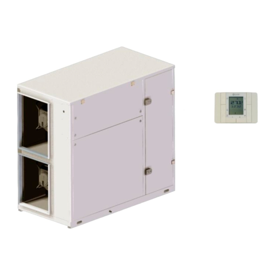
CPAN-XHE3
Make-up unit, full fresh air
With return/exhaust and thermodynamic heat recovery Reversible heat pump technology
Installation use and maintenance manual
M05G40L12-04
size1 - size6
17-11-16
Advertisement
Table of Contents

Subscribe to Our Youtube Channel
Related Manuals for CLIVET CPAN-XHE3


Summary of Contents for CLIVET CPAN-XHE3
- Page 1 CPAN-XHE3 size1 - size6 Make-up unit, full fresh air With return/exhaust and thermodynamic heat recovery Reversible heat pump technology Installation use and maintenance manual M05G40L12-04 17-11-16...
- Page 2 Dear Customer, Congratulations for having chosen this product. Clivet has been working for years to offer the market systems able to assure maxi- mum and long-lasting wellbeing with high reliability, efficiency, quality and safety. The company aim is that to offer its customers developed systems that assure the best comfort, reduce energy consumptions and installation and maintenance costs for the entire life-span of the system.
-
Page 3: Table Of Contents
TABLE OF CONTENTS Generality ......... Receipt ..........Positioning ........Hydraulic connections ....Aeraulic connections ...... Electric connections ....... Start-up ..........Control ........Maintenance ........Residue risks ........Disposal .......... Technical information ..... The data contained in this manual are not binding and can be changed by the manufacturer without prior notice. -
Page 4: Generality
1 - GENERALITY – 1.1 General warnings Fault Malfunctioning Disconnect the equipment in case of fault or Purpose of the manual malfunctioning. This manual has been realised to enable a correct installation, adjustment and maintenance of the unit. Repair Manual instructions For any repairs, only contact an after-sales technical It is of fundamental importance that the manual is carefully assistance centre authorised by the manufacturer and request... - Page 5 1 - GENERALITY MCHSX Steam-powered humidifying module 1.2 Machine identification Electronic filters std Matriculation plate ELECTRIC CIRCUIT The matriculation plate is found on the unit and indicates all Remote control with user interface std machine features. NCRC Remote control with user interface: not required The matriculation plate must never be removed.
-
Page 6: Receipt
2 - RECEIPT 2.1 Preliminary information 2.5 Handling Work respecting the current safety standards. Check the weight of the unit (TECHNICAL INFORMATION chapter) and capacity of the lifting mean. For detailed information (dimensions, weights, technical features, etc.) refer to the TECHNICAL INFORMATION chapter. Identify the critical points in the handling path (holy paths, ramps, steps, doors). -
Page 7: Positioning
3 - POSITIONING 3.1 Preliminary information difficulty of exchange Work respecting the current safety standards. leaves or other bodies that can obstruct the exchange For detailed information (dimensions, weights, technical coils features, etc.) refer to the TECHNICAL INFORMATION winds contrasting or favouring the air flow chapter. - Page 8 3 - POSITIONING Avoid snow and ice accumulating in front of the exhaust air 3.6 STEAM HUMIDIFICATION MODULE - OPTION ejection. IMMERSED ELECTRODE STEAM HUMIDIFICATION MODULE This accessory requires connection to a water supply network and discharge water circuit with adeguate frost protection. Requires its own power supply and have to be connected to the unit.
-
Page 9: Hydraulic Connections
4 - HYDRAULIC CONNECTIONS 4.2 Risk of freezing 4.1 Condensate drain The condensate must be disposed of in order to avoid Adopt measures to prevent risk of freezing if the unit or damaging things and persons. relative hydraulic connections can be subject to temperatures near 0°C. -
Page 10: Increases Humidifier Duration
4 - HYDRAULIC CONNECTIONS Limit values for the supply water with medium-high conductivity in an Immersed electrodes humidifier - option immersed electrode humidifier SUPPLY WATER The humidifier must be supplied with mains water having the Hydrogen ions following features: μS/cm Specific conductivity at 20°C 1250 ... -
Page 11: Aeraulic Connections
5 - AERAULIC CONNECTIONS 5.1 Generality 5.2 Treated air channelling The internal surface of the channel must be smooth, enable The dimensioning and correct execution of the aeraulic its washing and must not contaminate the air connections are fundamental to guarantee good unit operation and adequate level of silence in the room. - Page 12 5 - AERAULIC CONNECTIONS Remote supply air sensor (standard size 3, 4, 5, 6) 1. Probe kit position 2. Probe cable outlet...
-
Page 13: Electric Connections
6 - ELECTRIC CONNECTIONS 6.1 Preliminary information 6.4 Data-signal lines The features of the lines must be determined by personnel Do not exceed the maximum admitted distance, that varies enabled to the designing of electric systems, complying with based on the type of cable and signal. the standards in force. - Page 14 6 - ELECTRIC CONNECTIONS 6.6 Connections by the Customer - XC fire alarm remote ON-OFF selector remote SUMMER - WINTER selector HLC1 compressor status signal lamp supply fan status indicating light of the return and/or supply fan status remote alarm signal STEAM HUMIDIFICATION MODULE - OPTION...
- Page 15 6 - ELECTRIC CONNECTIONS 6.8 P.C. - not supplied 6.9 SERVICE KEYPAD - OPTION RJ45 : standard connection Shift RJ45 from T-IP to T-HI...
- Page 16 6 - ELECTRIC CONNECTIONS 6.10 Room keypad Distance up to 350 mt Connections Distance up to 700 mt user interface B = B1 KNX bus, max 350 mt twisted pair with shield, Ø 0,8 mm EIB/KNX cable marking recommended power supply unit N125/11 5WG1 125-1AB11 AC 120...230 V, 50...60 Hz...
-
Page 17: Start-Up
6 - ELECTRIC CONNECTIONS 6.11 MODBUS - RS485 Every RS485 serial line must be set up using the 'In/ Out' bus system. Other types of networks are not allowed, such as Star or Ring networks The difference in potential between the earth of the two RS485 devices that the cable shielding needs to be connected to must be lower than 7 V ... - Page 18 6 - ELECTRIC CONNECTIONS 6.12 BACNET 6.13 LONWORK LED BSP communication with AP1 module LED BSP communication with AP1 module green communication ok green communication ok yellow software ok but communication with AP1 yellow software ok but communication with AP1 down down flashing : software error...
-
Page 19: Control
7 - START-UP Preliminary checks Start-up sequence Checks with machine in OFF, before start-up . Machine start-up operations. For details refer to the various chapters in the manual. For details refer to the various chapters in the manual. √ √ unit ON power supply Unit OFF power supply ... - Page 20 7 - START-UP 7.1 Preliminary information 7.5 Electric circuit Check the unit is connected to the earth system. Check The indicated operations must be carried out by qualified fastening of the conductors: the vibrations caused by handling technicians and specifically trained on the product. and transport may cause loosening.
-
Page 21: Maintenance
7 - START-UP 7.7 Voltages 7.14 Start-up report Check the air and water temperatures are within the To detect the objective operational conditions is useful to operational limits. control the unit over time. Start the unit; refer to the "Adjustment" section for indications With the unit running, meaning in stable conditions and near on the control system. - Page 22 7 - START-UP 7.11 Maximum capacity available (MC) In this operating mode, the supply air temperature (T_SA) can vary in accordance with the temperature of the air extracted from the room (T_RA) and their deviation from the set value. Therefore, there is feedback from the room. In cooling mode the humidity control of the supply air is standard and a priority.
- Page 23 7 - START-UP The T_SA supply setpoint is calculated in relation to the SPR return setpoint. Set the values related to the T_SA supply air setpoint in relation to the T_RA return temperature: Main index \ Parameter machine \ Thermoregulator ...
- Page 24 7 - START-UP 7.12 Constant supply control (CS) In this operating mode the external air is treated based on the supply conditions set in accordance with one of the following two criteria: with two fixed seasonal setpoints, for operation in cooling and heating mode ...
- Page 25 7 - START-UP Temperature setpoint Set the values related to the T_SA supply air setpoint in relation to the T_OA external temperature: (Main index \ Parameter machine \ plant config) P0005 SetCool P0006 SetHeat P0010 CS_TExtCool P0011 CS_TExtHeat ...
- Page 26 7 - START-UP 7.13 High air flow (HA) In this operating mode the external air T_OA is treated until it reaches the value of the supply air temperature T_SA). There is no feedback from the room. The humidity control of the supply air is running only in heating mode. _Sa* solo con umidificatore Type of adjustment Main index \ Parameter machine \ Plant config...
- Page 27 7 - START-UP Humidity setpoint Main index \ Parameter machine \ Plant config set the specific return humidity setpoint in heating mode: P0018 SetXSR Confirm configuration Main index \ Parameter machine \ Plant config set P0020 ConfirmConf = Yes...
- Page 28 8 - CONTROL Keypad Keys and function change of status: OFF, ON, FAN ALARMS menu access (if available) set TIME and DATE set SCHEDULER (prolonged pressure) to browse through the menus to set values to browse through the menus to set values access to the STATUS menu to confirm your selection to access the PARAMETERS menu (password)
- Page 29 8 - CONTROL 8.1 PARAMETERS MENU press 16.3 C° the access by password is reserved to 17:00 qualified personnel, the parameters changes can cause malfunctions. enter password (0047) confirm scroll the parameters enable the parameter change P1 starts flashing change the value of the parameter confirm the new value select to enable the new value and exit...
- Page 30 8 - CONTROL 8.2 STATA MENU Press 16.3 C° 17:00 scroll the statuses 011.6 exit wait for 3 sec 16.3 C° when the time is displayed it is possible to carry out other 16.3 C° operations 17:00 Code Description Operating return temperature Outdoor temperature Supply temperature Return specific humidity...
- Page 31 8 - CONTROL 8.3 DATE AND HOUR 8.4 BUTTON LOCK Press Press for 4 sec. 16.3 C° 16.3 C° 17:00 17:00 HOUR digits start flashing enter password confirm edit _ _ _ _ 17:00 confirm MINUTE digits start flashing example: T0 = "-"...
- Page 32 8 - CONTROL 8.5 TO VISUALIZE ALARM IN PROGRESS Before resetting an alarm identify and remove its cause. Repeated resets can cause irreversible damage. press 16.3 C° only if the ALARM symbol is flashing 17:00 type of alarm (see table) generic alarm (1 circuit1 alarm, etc.) 0030...
- Page 33 8 - CONTROL Press 2 sec 8.6 SCHEDULER (only if the unit is not OFF) 16.3 C° Enable scheduler ( 8.1 menu parametres) 17:00 It is possible to set up to 7 schedules (1 for every day of the week) day 1 starts flashing It is possible to set up to 6 status changes for each day (On, Off, Eco, Fan).
- Page 34 8 - CONTROL Modify day 3 day scheduling - minutes of the event (ref. scheduling example) 05:30 Press 2 sec press 1 3 4 16.3 C° 17:00 - desired event 0 = null, 1 = OFF, 2 = ON, press 05:30 3 = Fan to schedule day 3 press (Wednesday)
- Page 35 8 - CONTROL 8.7 SERVICE KEYPAD Function keys Main menu Alarm display 27.03.2013 10:15:30 Supply T. Setpoint 22.0°C Exit Supply X. Setpoint 10.0 g/kg Previous level Keyboard settings StatoAttuale Increases value Cmp:23% Res: Off Battery:Off Down Decreases value Confirm Password 8.8 COMMON OPERATIONS main menu →...
- Page 36 8 - CONTROL 8.9 SCHEDULER 8.10 KEYBOARD SETTINGS It is possible to set 6 events (Off, Eco, On, Recirculating) for Press 3 sec each week day. Scheduler must be enabled: HMI settings Select display : actual value = On local connection : unit parameters service-maintenance, P0500=1 Confirm Select...
- Page 37 8 - CONTROL 8.11 ALARMS Before resetting an alarm identify and remove its cause. Repeated resets can cause irreversible damage. Press alarm log detail + eE001 : Phase monitor : Fault Last alarm Critico (A) 14.02.2012 11.30.10 Press Alarm list Acknowledge (*) alarm list + eE001 : Monitore fase : Fault...
- Page 38 8 - CONTROL Alarms encoding Alarms encoding Code Type Reset Code Type Reset Electrical From Auto to Man refr. circuit From Auto to Man Electrical Manual refr. circuit Manual Electrical Automatic refr. circuit Automatic Hydraulics From Auto to Man From Auto to Man Hydraulics Manual Manual...
- Page 39 8 - CONTROL ALARMS - Tab 2 Code Short description description ee101 TimeOutModCirc Circuit board not responding ee102 TimeOutDriver Expansion valve module not responding ee104 EEVBlockedOut Expansion valve blocked EE106 Comp 1 protections C1 compressor protection intervention EE107 Comp 2 protections C2 compressor protection intervention EE108 Comp 3 protections...
- Page 40 8 - CONTROL ALARMS - Tab 3 Code Short description description FF147 Alarm Envelop Comp1 - C1 Compressor 1 outside operating limits FF148 Alarm Envelop Comp2 - C1 Compressor 2 outside operating limits FF149 Alarm Envelop Comp3 - C1 Compressor 3 outside operating limits ff205 Min overheating Overheating too low...
- Page 41 8 - CONTROL P.C. CONNECTION connect P.C. and main module with LAN cable check in the taskbar that the connection is active Open Control panel and select Network and sharing center Select Modify board setting Select Local area connection (LAN) Select Internet protocol version 4 (TPC) IPV4 and enter Property Set the IP address 192.168.1.100 Set Subnet mask as 255.255.255.0...
- Page 42 9 - MAINTENANCE 9.1 Recommended periodical checks sheet Checks carried out on……………………..by……………………………...………….company…....……………………………………………. √ intervention frequency (months) □ presence corrosion □ panel fixing □ fans fixing □ coil cleaning □ bowl cleaning + sanitisation □ outflow test □ air filters cleaning/inspection □...
-
Page 43: Malfunctionings
9 - MAINTENANCE 9.2 Generality 9.7 G4 Folded air filters Maintenance must be carried out authorised after-sales It is very important for the air treatment coil to offer maximum assistance centres or by specialised personnel. thermal exchange: the unit must always work with clean and Maintenance allows: installed filters. - Page 44 To foresee a yearly replacement OF ALL WIRES avoids MATERIALS NECESSARY FOR MAINTENANCE unexpected breaks. 1. Acid detergent B01212 (code CLIVET C6460316) In case of break: : 2. plastic or steel tank (750x750x310 mm) with settling remove all wire pieces present in the cell and remove the bottom springs stretching the wire;...
- Page 45 9 - MAINTENANCE 9.9 Condensate collection bowl Dirt or scale can give rise to clogging. Also, microorganisms and mould can flourish in the bowl. It is very important to foresee periodical cleaning with suitable detergents and, eventually, disinfect with sanitising products. Once cleaning is completed, pour water inside the bowl to check the regular outflow.
- Page 46 9 - MAINTENANCE 9.11 Immerged electrodes humidifier- option check the seal gasket between the cylinder and the drain unit Do not use solvents or detergents to clean the plastic compo- remount the cylinder repeating the operations in reverse nents.
- Page 47 10 - RESIDUE RISKS Carry out all work on the electric system with reference to the wiring Generality diagram and this manual, assuring use of a dedicated system. The most common situations, as they cannot be controlled by the An incorrect fastening of the lid of the electric components can favour manufacturer, that may give rise to risk situations for things or persons entry of dust, water, etc.
- Page 48 11 - DISPOSAL 11.1 Disconnection The disconnection operations must be carried out by qualified technicians. Avoid pouring or leaking in room. Before disconnecting the unit recover, if present: : - the coolant gas - solutions to be cooled present inside the hydraulic circuits ...
-
Page 49: General Technical Data
General technical data General technical data - Performance Size Size 1 Size 2 SIZE 3 Size 4 Size 5 Size 6 Operation with constant supply temperature Standard air flow Nominal air flow 1278 2000 2638 3333 Nominal air flow m³/h 1300 2200 4600... - Page 50 General technical data - Construction Size Size 1 Size 2 SIZE 3 Size 4 Size 5 Size 6 Compressor Type of compressors Scroll Scroll Scroll Scroll Scroll No. of compressors Std Capacity control steps 20-100% 20-100% 10-100% 10-100% 8-100% 8-100% Refrigeration circuits Air Handling Section Fans (Supply) Type of supply fan...
-
Page 51: Sound Levels
Sound levels The sound pressure level refers to a distance of 1 meter from the outer surface of the unit operating in open field. Static pressure 50 Pa (UNI EN ISO 9614-2) For the standard air supply the total sound power levels for the diverse values of available static pressure are shown. Please note that when the unit is installed in conditions different from nominal test conditions (e.g. - Page 52 Operating ranges Operating range (Cooling) The limits are indicative and take into consideration: • general and non specific sizes • unit correctly installed and serviced Outdoor air 1 = Normal operating range T_OA = outdoor air temperature 2 = Operating range with capacity modulation T_RA = extracted air temperature 3 = With option RECH - “Hydronic recovery device”, with T_RA = 26°...
- Page 53 Operating range (Heating) The limits are indicative and take into consideration: • general and non specific sizes • unit correctly installed and serviced Outdoor air 1 = Normal operating range T_OA = outdoor air temperature 2 = Operating range with capacity modulation DB = dry bulb 3 = With “RECH - Hydronic recovery device”...
-
Page 54: Dimensional Drawings
Dimensional drawings SIZE 1 DAA5Gsize1_0 Date: 21/09/2012 (1) Capacity modulating compressor (2) Electrical panel (3) Power input (4) Condensation drain pipe Ø 20 mm (5) Standard outdoor air exchanger (below) (6) Exhaust air standard exchanger (above) (7) Capacity modulating post-heating with hot gas recovery (8) Hydronic recovery device for extended operating range (Optional) (9) Electrical heaters (10) Electronic filters... - Page 55 SIZE 2 DAA5Gsize2_0 Date: 21/09/2012 (1) Capacity modulating compressor (2) Electrical panel (3) Power input (4) Condensation drain pipe Ø 20 mm (5) Standard outdoor air exchanger (below) (6) Exhaust air standard exchanger (above) (7) Capacity modulating post-heating with hot gas recovery (8) Hydronic recovery device for extended operating range (Optional) (9) Electrical heaters (10) Electronic filters...
- Page 56 SIZE 3 DAA5Gsize3_0 Date: 21/09/2012 (1) Capacity modulating compressor (2) Electrical panel (3) Power input (4) Condensation drain pipe Ø 20 mm (5) Standard outdoor air exchanger (below) (6) Exhaust air standard exchanger (above) (7) Capacity modulating post-heating with hot gas recovery (8) Hydronic recovery device for extended operating range (Optional) (9) Electrical heaters (10) Electronic filters...
- Page 57 Size 4 DAA5Gsize4_0 Date: 21/09/2012 (1) Capacity modulating compressor (2) Electrical panel (3) Power input (4) Condensation drain pipe Ø 20 mm (5) Standard outdoor air exchanger (below) (6) Exhaust air standard exchanger (above) (7) Capacity modulating post-heating with hot gas recovery (8) Hydronic recovery device for extended operating range (Optional) (9) Electrical heaters (10) Electronic filters...
- Page 58 SIZE 5 DAA5Gsize5_0 Date: 21/09/2012 (1) Capacity modulating compressor (2) Electrical panel (3) Power input (4) Condensation drain pipe Ø 20 mm (5) Standard outdoor air exchanger (below) (6) Exhaust air standard exchanger (above) (7) Capacity modulating post-heating with hot gas recovery (8) Hydronic recovery device for extended operating range (Optional) (9) Electrical heaters (10) Electronic filters...
- Page 59 SIZE 6 DAA5Gsize6_0 Date: 21/09/2012 (1) Capacity modulating compressor (2) Electrical panel (3) Power input (4) Condensation drain pipe Ø 20 mm (5) Standard outdoor air exchanger (below) (6) Exhaust air standard exchanger (above) (7) Capacity modulating post-heating with hot gas recovery (8) Hydronic recovery device for extended operating range (Optional) (9) Electrical heaters (10) Electronic filters...
- Page 60 Tel. +34 91 6658280 - Fax +34 91 6657806 - info@clivet.es CLIVET GmbH Hummelsbütteler Steindamm 84, 22851 Norderstedt - Germany Tel. + 49 (0) 40 32 59 57-0 - Fax + 49 (0) 40 32 59 57-194 - info.de@clivet.com CLIVET RUSSIA Elektrozavodskaya st. 24, office 509 - 107023, Moscow, Russia Tel.
Need help?
Do you have a question about the CPAN-XHE3 and is the answer not in the manual?
Questions and answers