
Related Manuals for CLIVET WSAT-2


Summary of Contents for CLIVET WSAT-2
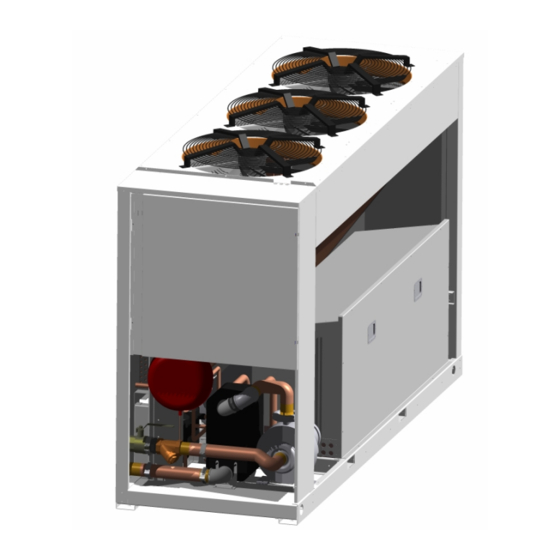
- Page 1 302-323-404 WSAT-2 464-524-564-614 (R-407C / R-22) OOLED HILLER CROLL OMPRESSORS WITH PROPELLER FANS Installation and Use Manual M91P44E5-05 ®...
-
Page 3: Table Of Contents
O N T E N T S DIMENSIONS ..................... 11 ENERAL NFORMATION WEIGHT DISTRIBUTION ................12 GENERAL WARNINGS ................2 POSITIONING .................... 12 CORRECTION FACTORS ................2 OPERATION LIMITS AND USE OF THE EXCHANGERS......2 ESIDUAL ISKS GENERAL SPECIFICATIONS ..............3 OPERATING LIMITS.................. -
Page 4: General Information
Dteo Dtei [kPa] [kPa] [°C] [°C] [°C] B (*) CLIVET 3450 2500 3450 3450 DPr = Maximum operating pressure at refrigerant side DPw = Maximum operating pressure at water side DTeo = Minimum water temperature at evaporator outlet DTei = Maximum water temperature at evaporator inlet... -
Page 5: General Specifications
GENERAL SPECIFICATIONS Version S / Configuration ST SIZE Cooling Cooling capacity [kW] 81.4 93.5 101.5 119.1 134.3 144.0 159.5 Compr.input power [kW] 26.3 28.6 33.1 37.3 42.0 46.7 54.5 Total input power [kW] 30.2 32.5 37.1 43.0 47.7 52.4 60.2 COMPRESSORS Compressors type scroll... - Page 6 Version S / Configuration LN SIZE Cooling Cooling capacity [kW] 79.2 89.6 98.4 115.9 129.1 137.4 153.3 Compr.input power [kW] 27.6 29.8 34.9 39.1 44.1 49.4 57.6 Total input power [kW] 30.1 32.2 37.4 42.6 47.8 52.9 61.2 COMPRESSORS Compressors type scroll scroll scroll...
-
Page 7: Operating Limits
OPERATING LIMITS The water flow-rate at the evaporator must be constant and fall within MIN-MAX limits shown in the diagram/diagrams under the section on "Water/Aeraulic Connections". Version S / Configuration ST SIZE Condenser Max. air inlet temperature [°C] 47.5 47.5 47.5 48.5 Max. -
Page 8: Sound Levels
SOUND LEVELS Version S / Configuration ST Sound Size SOUND POWER LEVEL (dB) Sound Pressure Power Level Level Octave Band (Hz) 1000 2000 4000 8000 dB(A) dB(A) Version S / Configuration LN Sound Size SOUND POWER LEVEL (dB) Sound Pressure Power Level Octave Band (Hz) Level... -
Page 9: Regulations And Certifications
CE MARK Clivet products bear the CE mark, in compliance with the requirements of the following EC directives, including the latest amendments, and with the corresponding national approximated legislation: - 98/37/CE... -
Page 10: Reception /Positioning
E C E P T I O N O S I T I O N I N G INSPECTION UPON RECEPTION The units are shipped in special protective packaging. Check upon receipt that the unit has not been damaged during transport, and that all the parts ordered are present. - Page 11 HOISTING USING A SELF-BALANCING FORK Insert the self-balancing fork in the special slits of the unit. A rigid protective structure should be placed on the upper edge of the unit, on the side facing the fork. Start hoisting the unit, making sure the load is in steady equilibrium. Reception/Positioning ®...
-
Page 12: Removing The Packing
Spring or rubber (depending on the type of unit) antivibration mounts can be supplied upon request; in this case flexible joints (not supplied by Clivet) are required for the hydraulic / aeraulic / refrigerant connections. The tables and the drawings show the instructions for the installation of the antivibration mounts, with the part numbers of the antivibration kits and their composition for correct installation. -
Page 13: Dimensions
ANTIVIBRATION MOUNTS CODES UNIT CODE POSITIONING W1 = cod. C6100080 K=21,2 W2 = cod. C6100080 K=21,2 PE581072 W3 = cod. C6100080 K=21,2 W4 = cod. C6100080 K=21,2 W1 = cod. C6100080 K=21,2 W2 = cod. C6100082 K=25,6 PE581051 W3 = cod. C6100080 K=21,2 W4 = cod. -
Page 14: Weight Distribution
Place a layer of rubber between the base of the unit and the support to prevent noise and vibrations. Depending on the place of installation (balconies or roofs), the unit should be placed on special antivibration mounts (in this case, flexible joints are required for the water/aeraulic connections - joints are not supplied by Clivet). Fasten the unit to the ground. -
Page 15: Esidual Isks Safety Instructions
E S I D U AL I S K S SAFETY INSTRUCTIONS CAUTION THIS BULLETIN DESCRIBES EVERY OPERATION THAT MAY CAUSE A SITUATION OF RISK, AS WELL AS THE PRECAUTIONARY MEASURES TO BE HEEDED IN EACH CASE DEFINITION OF DANGER AREA The figure below highlights the area in which only authorised personnel may operate. -
Page 16: Danger
- Check that there are no refrigerant gas leaks once installation has been completed. - In the case of anomalies (burning smell, smoke) stop the appliance and turn off the automatic switch. Continuing to operate the unit in abnormal conditions may cause fire, damage, etc. Contact the manufacturer’s authorised service centre. - Avoid accidental contact with the exchanger coils, by always using protective gloves and applying the special protective grilles. - Page 17 IDENTIFICATION OF RISK Greatest physical and chemical dangers: - Thermal decomposition in toxic and corrosive products FIRST-AID MEASURES General information: - Inhalation: Carry the victim into the open air. Resort to oxygen or artificial respiration if necessary. - Contact with skin: Frostbite must be treated in the same way as burns. - Contact with the eyes: Immediate rinsing in abundant water.
- Page 18 y (estimated). . Potential for destruction of ozone ODP (R-11 = 1)=0. Potential greenhouse effect (GWP): (HGWP) = 0,58. Low absorption in ground and sediments log Koc= 1,3-1,7 - Bioaccumulation: Practically non-absorbable by biological organisms log pow 1,48 Forane 134a - Mobility: Rapid evaporation t ½...
- Page 19 France 1989: VME = 1000 USA 1992: TWA = 1000 p.p.m. = 3500 mg/m3 - Individual protective equipment: Respiratory protection: In case of insufficient ventilation, carry suitable breathing apparatus. Protection for the hands: Gloves Protection for the eyes: Protective eyewear. - Specific hygiene measures: avoid contact with the skin, eyes and inhalation of the vapours.
-
Page 20: Ecommissioning Of The Unit Disconnecting The Unit
E C O M M I S S I O N I N G O F T H E U N I T DISCONNECTING THE UNIT - The units must be disconnected by authorised personnel, who before proceeding must first read the Residual Risks section in this manual. -
Page 21: Water/Aeraulic Connections
AT E R E R A U L I C O N N E C T I O N S GENERAL Install ON/OFF valves next to the parts that are subject to maintenance. This allows their replacement without having to empty the system. -
Page 22: Evaporator Pressure Drops (Water Side)
If the unit is not supplied with a pumping station, follow what outlined in the picture for the passage of the water inlet and outlet tubes. EVAPORATOR PRESSURE DROPS (WATER SIDE) The unit is not available with pressure drops lower than 20kPa. EVAPORATOR ANTIFREEZE SOLUTIONS % ETHYLENE GLYCOL BY WEIGHT Freezing point... -
Page 23: Water Flow Limits
302 UNIT 340 kPa 320 kPa 300 kPa 280 kPa 260 kPa 240 kPa 220 kPa 200 kPa 180 kPa 160 kPa 140 kPa 120 kPa 1 (std) 100 kPa 80 kPa 3.0l/s 3.5l/s 4.0l/s 4.5l/s 5.0l/s 5.5l/s 6.0l/s 323-404 UNIT 340 kPa 320 kPa 300 kPa... -
Page 24: Electrical Connections
N.B. For connection to a CLIVET pumping assembly, the water pump is controlled at 230V, therefore, in the event of maintenance, isolate both electrical panels. This is an important warning for the safety of the operator. -
Page 25: Enabling The Second Set Point From Digital Input
- REMOTE MACHINE ALARM SIGNAL The unit is fitted with a relay that is activated whenever a machine alarm condition arises. The contact of this relay, which is normally open when no alarm is present, is connected to the two terminals for the remote signal. Refer to the machine’s wiring diagram. - Page 26 Version S / Configuration LN SIZE F.L.A. Full load current at max admissible conditions Compressor 1 400/3/50 29.8 19.5 19.5 25.3 25.3 29.2 29.8 Compressor 2 400/3/50 29.8 29.2 19.5 19.5 25.3 25.3 29.8 Compressor 3 400/3/50 19.5 19.5 25.3 25.3 29.2 29.8...
-
Page 27: Start - Up
TAR T GENERAL ALL THE EQUIPMENT MUST BE COMMISSIONED BY AUTHORISED SERVICE CENTRES. THIS SERVICE IS LIMITED TO START-UP OF THE UNIT ONLY AND NOT THE CONNECTIONS OR INSTALLATION OF THE SYSTEM PRELIMINARY CHECKS BEFORE PERFORMING ANY TYPES OF CHECKS, MAKE SURE THAT THE UNIT IS PROPERLY INSTALLED AND CONNECTED PRELIMINARY CHECKS: ELECTRICAL SYSTEM CAUTION: Before performing the checks described below, make sure that the unit’s electrical power line is disconnected at the source. -
Page 28: Preliminary Checks: Water System
PRELIMINARY CHECKS: WATER SYSTEM NITROGEN CUSHION SETTING IN THE EXPANSION VESSEL ACCORDING TO THE CAPACITY OF THE GLOBAL INTALLATION 14 0 0 12 0 0 10 0 0 8 0 0 6 0 0 4 0 0 2 0 0 1. -
Page 29: Electrical Checks
Turn the unit ON using the ON-OFF button (or switch). Press the MODE button to select COOLING OPERATION. Press the MODE button again to select HEATING OPERATION (heat pump only). The control system will enable the compressor to start after the pre-set safety times. If the unit has more than one compressor, one will start after the pre-set safety times, and the others will start in sequence after the first. -
Page 30: Control
O N T R O L MAIN CONTROL MODULE KEYPAD The figure shows the user interface panel present on the unit, with the description of the main screen. 1 . D A Y DATE TIME 2. UNIT STATUS 3. OPERATING MODE 4. -
Page 31: Alarms
ALARMS TYPE OF ALARM ALARM DESCRIPTION RESET ACTION DISPLAYED E1 - BT1 ALL Probe BT1 alarm Automatic Signal E2 - BT2 ALL Probe BT2 alarm Automatic Complete shutdown – Pump on E3 - BT3 ALL Probe BT3 alarm Automatic Complete shutdown – Pump on E4 - BT4 ALL Probe BT4 alarm Automatic... -
Page 32: Selecting The Operating Mode
SELECTING THE OPERATING MODE In heat pump units the operating mode can be selected on the main interface module. The procedure for doing this is shown below. The procedure describes how to switch from COOLING to HEATING. To switch from HEATING to COOLING, perform the same procedure, but this time selecting COOLING. -
Page 33: Setting The Working Set Point
SETTING THE WORKING SET POINT The flow chart shown provides an example of the procedure for accessing the SET POINT parameters. This starts from the main screen and ends again at the main screen when the procedure is complete. The example assumes that the unit is a heat pump, and thus describes both the COOLING SET POINT and the HEATING SET POINT. -
Page 34: Setting The Second Set Point For Heating And Cooling
A second set point, for both COOLING and HEATING operation, can be enabled by digital input. This function, unless requested when ordering, must first be enabled by an authorised CLIVET service centre. If the function is enabled, the sequence shown illustrates the phases to be followed for entering the desired set point values. The closing of the remote contact is used to switch from the normal working set point to the second set point. -
Page 35: Setting The Maintenance Set Point
A maintenance SET POINT can be enabled for both COOLING and HEATING mode. This function, unless requested when ordering, must first be enabled by an authorised CLIVET service centre. If the function is enabled, the sequence shown illustrates the phases to be followed for entering the desired set point values. -
Page 36: Setting The Clock
SETTING THE CLOCK The control board is fitted as standard with the clock function. The sequence shown illustrates the phases to be followed for the correct setting of all the parameters (hours, minutes, seconds, weekday, day of the month, month, year). Important: remember to confirm the data entered by selecting the "MEM"... -
Page 37: Switching On And Off From Time Bands
SWITCHING ON AND OFF FROM TIME BANDS The microprocessor offers the possibility to enter time bands for switching the unit ON or OFF. A maximum of 14 events can be set for each weekday. The information that needs to be set is the time (time to start a new band and end the previous one) and the status (ON or OFF). To enable the Time band function, set the parameter EnableTZ to On. - Page 38 After having set all the time bands, confirm the data entered using the "MEM" parameter. The procedure described can be performed simply by following the flow chart shown. Mon 11-04-2002 10:12:37 Mon 11-04-2002 10:12:37 Mon 11-04-2002 10:12:37 TM SET STATUS Unit SET COOL Mode...
-
Page 39: Counter Display
COUNTER DISPLAY The operating hours and starts corresponding to each compressor installed on the unit can be checked. The operating hours of the pumps can be displayed. The procedure for accessing these values is described in the flow chart. 1. Configuration Menu 8. -
Page 40: Layout Of The Main Module
LAYOUT OF THE MAIN MODULE The layout of the main board is shown for easy identification of the inputs and outputs. DI DI DI DI DO11 +12V +12V +12V +12V AI10 AI11 Control ®... -
Page 41: Reading The Operating Status
READING THE OPERATING STATUS The status of the inputs and outputs on the main control module can be monitored. The sequence for accessing this menu is shown. The paragraph on "Digital inputs" provides a more detailed description of the last 5 items. Control ®... -
Page 42: Digital Inputs
1. Status menu 18. Outside air specific humidity 2. Date and time 19. Status of compressor 1 3. Current set point 20. Status of compressor 2 4. Outside Temperature Compensation Value 21. Status of compressor 3 5. Water Reset Compensation Value 22. -
Page 43: Demand Limit
This function must be enabled by an authorised Clivet service centre or by Clivet directly. UNITS WITH 4 COMPRESSORS: A. -
Page 44: Antifreeze Pre-Alarm Thermoregulator
ANTIFREEZE PRE-ALARM THERMOREGULATOR The antifreeze pre-alarm function is active in all operating modes. The purpose of the function is to prevent the evaporator outlet water temperature from falling too low, and thus causing the unit to shut-down due to the antifreeze alarm. The function acts as follows: if the evaporator outlet temperature is less than or equal to the pre-alarm threshold, one compressor capacity-control step is deactivated, according to the compressor rotation requirements. -
Page 45: Connecting The Unit To Supervisory Systems
CONNECTING THE UNIT TO SUPERVISORY SYSTEMS The H2OSYSTEM control module is fitted, as standard, with an RS485 serial communication port. It can thus communicate with the outside world using a standard MODBUS protocol. The RS485 serial port is located on the main board, and is made up of a series of three terminals marked 43(-), 44(+) and 45(GND). These can be connected in a network, up to a maximum of 127 units. - Page 46 SERIAL CONNECTION DIAGRAM TO THE SUPERVISORY SYSTEM RS485 RS485 RS485 RS485 1. System supervisor. Software to be provided by customer 2. RS485/RS232 converter 3. Shield 4. RS485 serial line. ModBus protocol. Twisted pair + shield 5. Insert Jumper JP1 as the line termination at both ends of the serial line. 6.
-
Page 47: Communication Protocol
COMMUNICATION PROTOCOL The ModBus communication protocol is used. All the data contained in the H2OSYSTEM control module are organised into words, where the significant part is only LO. Only the following functions are envisaged: - 04 (reading of single register at 16 bits) - 06 (writing of single register at 16 bits). - Page 48 LIST OF VARIABLES PASSWORD LOGICAL AREA (0xBB) WRITE Function Address Description 06(write) 0xBB 0x00 Level 1 password (Maintenance) 0x01 Level 2 password (Manufacturer) 0x02 Manual alarm reset password When writing the alarm reset password to the address 0xBB02, all the alarms on the unit, if the causes are no longer present, will be reset.
- Page 49 UNIT STATUS LOGICAL AREA (0x00) WRITE function DESCRIPTION VALUE Bit 0= 1: Test Bit 1= 1: Heat Bit 2= 1: On (remote) 0= Off Bit 3= 1: Cool 06(write) 0x13 Operating mode command Bit 4= 1: -- Bit 5= 1: -- Bit 6= 1: On (local) 0= Off Bit 7= 1: -- IMPORTANT: USING THE OPERATING MODE COMMAND.
- Page 50 DIGITAL OUT BIT MAP, PLUG-IN EXPANSION BOARD Bit no. Alarm description Fans, circuit 2 (DO14) Fans, circuit 1 (DO13) Pump 2 (DO12) Bit = 0: Relay de-energised - Bit = 1: Relay energised DIGITAL IN BIT MAP Bit no. Alarm description Compressor 1 protection devices Fan safety or water flow devices, circuit 1 High pressure circuit 2...
- Page 51 NOTE: any of the parameters relating to the software that controls the unit can be monitored and modified. If the variables that are accessible without requiring the password (password level "0") are insufficient, contact the Clivet service centre, which will provide all the necessary information. Control...
-
Page 52: Routine Maintenance
O U T I N E AI N T E N AN C E GENERAL IMPORTANT BEFORE STARTING ANY MAINTENANCE OR CLEANING OPERATIONS ON THE UNIT, MAKE SURE IT IS NOT POWERED Few operations performed carefully and regularly may avoid the need for special maintenance. IMPORTANT AUTHORISED PERSONNEL SHOULD BE PRESENT WHEN THE UNIT IS STARTED FOR THE FIRST TIME EACH SEASON, SO AS TO PERFORM THE CHECKS DESCRIBED ABOVE, AS WELL AS THE CHECKS ON THE REFRIGERANT CIRCUIT, AS... - Page 53 REFRIGERANT TABLES LBS - R.F. R-22 R-134a R-407C R-22 R-134a R-407C P (bar) Ts (°C) Ts (°C) Te (°C) Tc (°C) P (bar) Ts (°C) Ts (°C) Te (°C) Tc (°C) -40.89 -26.22 -39.43 -40.53 -36.97 -44.10 11.44 27.39 11.13 10.03 13.10 6.96...
- Page 54 REFRIGERANT TABLES LBS - R.F. R-22 R-134a R-407C R-22 R-134a R-407C P (bar) Ts (°C) Ts (°C) Te(°C) Ts (°C) P (bar) Ts (°C) Ts (°C) Te(°C) Ts (°C) 12.2 18.3 33.99 50.32 32.65 31.55 34.29 28.80 49.71 66.12 47.48 46.38 48.82 43.95...
-
Page 55: Troubleshooting
R O U B L E S H O O T I N G GENERAL The aim of the following sections is to provide possible solutions to a number of anomalies that may arise on the unit. The information provided does not cover the entire range of possible cases. The activation of a safety device indicates abnormal operation; before resetting it, check and eliminate the causes. -
Page 56: The Unit Is Noisy
THE UNIT IS NOISY - Check that the panelling is correctly fastened. - Check that the antivibration materials installed at the anchor points are in good condition. - Check, if present, the condition of the shock absorbers on the compressor. - Check the correct direction of rotation of the compressor/s. - Page 57 ®...
- Page 58 ® Clivet S.p.A. Clivet España S.A. Clivet UK Ltd Clivet Nederland B.V. Feltre (BL) - ITALY Madrid - SPAIN Sevenoaks (Kent) - U.K. Amersfoort - Netherlands Fareham (Hampshire) - U.K. tel. +39 0439 3131 tel. +34 916 852344 tel. +44 (0) 1732 464141 tel.
Need help?
Do you have a question about the WSAT-2 and is the answer not in the manual?
Questions and answers