CLIVET MC2-Y 53M Technical Manual
Light commercial r32. cassette 650x650 box-sl 2. outdoor unit-sl 2. only size 53m
Hide thumbs
Also See for MC2-Y 53M:
- Manual (144 pages) ,
- Technical manual (108 pages) ,
- Technical manual (90 pages)

Related Manuals for CLIVET MC2-Y 53M


Summary of Contents for CLIVET MC2-Y 53M
- Page 1 LIGHT COMMERCIAL R32 CASSETTE 650x650 Box-SL 2 Outdoor unit-SL 2 Only size 53M TECHNICAL MANUAL TM19A066GB-00 18/01/2019...
-
Page 2: Table Of Contents
Table of Contents Page 1. Specifications ....................3 Model Reference General Specifications Dimensional Drawings Centre of Gravity Electrical Wiring Diagrams Refrigerant Cycle Diagrams Capacity Tables Capacity Correction Factor for Height Difference Noise Criterion Curves Electrical Characteristics 2. Product Features ................... 28 Operation Modes and Functions Remote Controller Functions 3. -
Page 3: Specifications
Specifications Contents Model Reference ....................4 General Specifications ...................5 Dimensional Drawings ..................7 Centre of Gravity ....................9 Electrical Wiring Diagrams ..................10 Refrigerant Cycle Diagrams ................20 Capacity Tables ....................21 Capacity Correction Factor for Height Difference ..........24 Noise Criterion Curves ..................25 Electrical Characteristics ..................27... -
Page 4: Model Reference
Refer to the following table to determine the specific indoor and outdoor unit model number of your purchased equipment. Outdoor Unit Model indoor Unit Model Capacity (Btu/h) Power Supply 1 ɸ , 220~240V~, 50Hz MC2-Y 53M IB2-XY 53M Page 4 ... -
Page 5: General Specifications
2. General Specifications Indoor Model IB2-XY 53M Outdoor Model MC2-Y 53M Power supply (Indoor ) V- Ph-Hz 220~240-1-50 Power supply (Outdoor ) V- Ph-Hz 220~240-1-50 Max. Input consumption 2950 Max. Current 13.5 Model ZKFP-46-8-1 Indoor fan motor Input 45.0 Capacitor μF... - Page 6 Number of rows Tube pitch(a)x row pitch(b) 21x22 Fin spacing Condenser Fin type (code) Hydrophilic aluminum ɸ 7,Inner groove tube Tube outside dia. and type Coil length x height x width 860x504x44 Number of circuits Outdoor side air flow(Hi) m3/h 2000 Outdoor sound pressure level dB(A)
-
Page 7: Dimensional Drawings
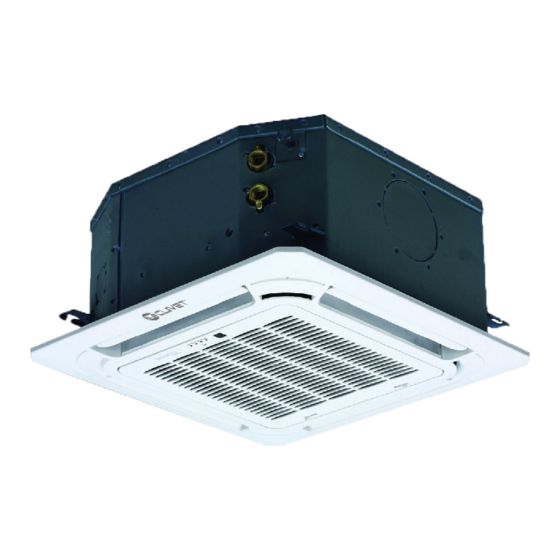
3. Dimensional Drawings Indoor Unit Cassette 650x650 BOX-SL 2 Page 7 ... - Page 8 Model Unit MC2-Y 53M inch 31.49 13.11 21.81 34.25 20.23 13.39 14.37 Page 8 ...
-
Page 9: Centre Of Gravity
4. Centre of gravity MC2-Y 53M Page 9 ... -
Page 10: Electrical Wiring Diagrams
5. Electrical Wiring Diagrams Indoor unit Abbreviation Paraphrase Yellow-Green Conductor CAP1 Indoor Fan Capacitor FAN1 Indoor Fan LIVE NEUTRAL TO CCM Comm.Bus Central Controller Indoor Room Temperature Coil Temperature of Indoor Heat Exchanger Super High Speed High Speed Page 10 ... - Page 11 IB2-XY 53M 16022500004023 NOTE: Inner Driver WIRING DIAGRAM FOR FAN MOTER Anti-cold air The wiring diagram TO WIRE SWITCH CONTROL THEN NO DC Motor NEWFAN Alarm Remote (INDOOR UNIT) POWER REQUEST. is for explanation CONTROLLER Output Control purpose only. The FAN MOTOR STOP-TEM FUNCTION OF SWITCH actual shape of the...
- Page 12 5.2 Some connectors introduce: A For remote control (ON-OFF) terminal port CN23 and short connector of JR6 1. Remove the short connector of JR6 when you use ON-OFF function; 2. When remote switch off (OPEN) ;the unit would be off; 3.
- Page 13 B For ALARM terminal port CN33 1. Provide the terminal port to connect ALARM ,but no voltage of the terminal port , the power from the ALARM system (not from the unit ) 2. Although design voltage can support higher voltage ,but we strongly ask you connect the power less than 24V, current less than 0.5A 3.
- Page 14 C. For new fresh motor terminal port CN8 1. Connect the fan motor to the port , no need care L/N of the motor ; 2. The output voltage is the power supply; 3. The fresh motor can not excess 200W or 1A , follow the smaller one ; 4.
- Page 15 5.3 Micro-Switch introduce: A. Micro-switch SW1 is for selection of indoor fan stop temperature (TEL0) when it is in anti-cold wind action in heating mode. Range: 24 C, 15 C, 8 C, According to EEROM setting (reserved for special customizing). B.Micro-switch SW2 is for selection of indoor FAN ACTION if room temperature reaches the setponit and the compressor stops.
- Page 16 C.Micro-switch SW3 is for selection of auto-restart function. Range: Active, inactive SWITCH FOR MODE-PRIOR SETTING STATE COOL MODE HEAT HEAT COOL Factory Setting D. Micro-switch SW5 is for setting mode priority of multi connection. Range: Heat, cool. E.Micro-switch SW6 is for selection of temperature compensation in heating mode. This helps to reduce the real temperature difference between ceiling and floor so that the unit could run properly.
- Page 17 G.Micro-switch S1 and dial-switch S2 are for address setting when you want to control this unit by a central controller. Range: 00-63 32~35 36~53 54~71 72~90 91~105 106~140 141~160 161~200 H. Dial-switch ENC1: The indoor PCB is universal designed for whole series units from 7K to 68K. This ENC1 setting will tell the main program what size the unit is.
- Page 18 Outdoor Unit Abbreviation Paraphrase CAP1, CAP2, CAP3,CAP4 Fan Motor Capacitor FM1,FM2 Outdoor DC Fan FAN1, FAN2 Outdoor AC Fan HEAT, HEAT_Y,HEAT_D CRANKCASE HEATING CT1, CT2 AC Current Detector COMP Compressor L-PRO Low Pressure Switch H-PRO High Pressure Switch PFC Inductor 4-Way Valve TRANS Power Transformer...
- Page 19 MC2-Y 53M Notes: This symbol indicates the YELLOW OR BLACK element is optional,the BLUE actual shape shall be prevail. BROWN 1(L) 2(N) CN 3 CN 1 CN 2 CN 16 CN 1A INDOOR UNIT OPTIONAL POWER SUPPLY CN 60 REACTOR...
-
Page 20: Refrigerant Cycle Diagrams
6. Refrigerant Cycle Diagrams Pipe Size (Diameter:ø) Piping length (m/ft) Elevation (m/ft) mm(inch) Model No. Additional Refrigerant Liquid Rated Max. Rated Max. MC2-Y 53M 12.7(1/2) 6.35(1/4) 5/16.4 30/98.4 20/65.6 12g/m (0.13oz/ft) Page 20 ... -
Page 21: Capacity Tables
7. Capacity Tables Cooling IB2-XY 53M+ MC2-Y 53M ID WB 16.0 18.0 19.0 22.0 INDOOR (℃) OUTDOOR AIRFLOW DB(℃) ID DB (CMH) 23.0 25.0 27.0 29.0 23.0 25.0 27.0 29.0 23.0 25.0 27.0 29.0 23.0 25.0 27.0 29.0 (℃) 5.50 5.50... - Page 22 5.62 5.62 5.62 5.68 5.90 5.90 5.90 5.90 6.06 6.06 6.06 6.06 6.43 6.43 6.43 6.43 0.68 0.75 0.98 1.00 0.55 0.63 0.70 0.76 0.49 0.56 0.63 0.70 0.36 0.42 0.48 0.55 1.11 1.11 1.11 1.11 1.10 1.10 1.10 1.10 1.10 1.10 1.10...
- Page 23 Heating IB2-XY 53M+ MC2-Y 53M [SI_Unit] HEATING PERFORMANCE AT INDOOR DRY BULB TEMPERATURE TC:TOTAL CAPACITY IN KILOWATTS (KW) PI:TOTAL POWER IN KILOWATTS (KW) INDOOR OUTDOOR AIRFLOW (CMH) Indoor Conditions (DB °C ) Indoor Conditions (DB °C ) DB(°C) 16.0 20.0 22.0...
-
Page 24: Capacity Correction Factor For Height Difference
8. Capacity Correction Factor for Height Difference Model Pipe Length (m) Cooling 0.928 0.912 Indoor Upper 0.969 0.937 0.921 than Outdoor 0.995 0.979 0.946 0.930 Height difference 1.000 0.984 0.951 0.935 H (m) 1.000 0.984 0.951 0.935 Outdoor Upper 0.984 0.951 0.935 than Indoor... -
Page 25: Noise Criterion Curves
9. Noise Criterion Curves Indoor Unit Notes: -Sound measured at 1.4m away from the noisiest location of the unit. -Data is valid at free field condition -Data is valid at nominal operation condition -Reference acoustic pressure OdB = 20μPa -Sound level will vary depending on a range of factors such as the construction -(acoustic absorption coefficient) of particular room in which the equipment is installed. - Page 26 -Reference acoustic pressure OdB=20μPa -Sound level will vary depending on arrange off actors such as the construction (acoustic absorption coefficient) of particular room in which the equipment is installed. -The operating conditions are assumed to be standard. MC2-Y 53M Cooling Heating NC-70...
-
Page 27: Electrical Characteristics
10. Electrical Characteristics Type Phase 1-phase Frequency and Voltage 220-240V, 50Hz Circuit Breaker/ Fuse (A) 25/20 Indoor Unit Power Wiring (mm Outdoor Unit Power Wiring (mm 3×2.5 Ground Wiring Indoor/Outdoor Connecting Wiring Strong Electric Signal 4×1.0(4x2.5 with auxiliary electric heater) Weak Electric Signal ... -
Page 28: Product Features
Product Features Contents Operation Modes and Functions ................29 Abbreviations ....................29 Safety Features ....................29 Digital Display ....................29 Fan ......................30 Cooling Mode .....................30 Heating Mode .....................30 Auto Mode ....................32 Drying Mode ....................32 Forced Operation Function ................32 1.10 Timer Function ....................32 1.11 ECO Function ....................32 1.12 Auto-Restart ....................32 1.13 Drain Pump Control ..................33 1.14 8°C Heating Control(optional) ..............33... -
Page 29: Operation Modes And Functions
1. Operation Modes and Functions Lack of phase DC voltage too low Abbreviation Communication fault Parameter fault Unit element abbreviations L3 Current limited Abbreviation Element L5 Voltage limited Indoor room temperature Target speed cannot be met Coil temperature of evaporator during the static pressure calculation process Coil temperature of condenser... -
Page 30: Fan
Fan Mode 1.5.2 Indoor Fan Control 1) In cooling mode, the indoor fan operates continuously. When fan mode is activated: The fan speed can be set to 1%-100%, or low, medium, high and auto. • The outdoor fan and compressor are stopped. •... - Page 31 minimum limit frequency(FminH). 2) Auto fan action in heating mode: • When protective time is more than or equal to ten • Rise curve minutes. • When T1-Tsc is higher than -1.5°C, fan speed • When T1 is higher than or equal to Tsc+ reduces to 80%;...
-
Page 32: Auto Mode
Auto Mode • fan speed • sleep mode • This mode can be selected with the remote controller • Follow me and the temperature setting can be adjusted between 16°C~30°C. 1.10 Timer Function • In auto mode, the machine selects cooling, heating, or fan-only mode on the basis of ∆T (∆T =T1-TS). -
Page 33: Drain Pump Control
1.13 Drain Pump Control(Standard for 1.17 Silence(Optional) cassette type) • Press “Silence” on the remote control to enable the SILENCE function. While this function is active, the • Use the water-level switch to control drain pump. compressor frequency is maintained at a lower level •... -
Page 34: Remote Controller Functions
2. Remote Controller Functions 2.1 LCD Wired Remote Controller KJR-120C1E(Optional) The KJR-120C1E wired remote controller is optional for all types. i) Buttons and Functions swing swing 1. POWER button 7. FOLLOW ME(PTC) button Turn on of turn off the unit. Allows the remote control to act as a remote thermostat and send temperature information from its current 2. - Page 35 ii) LCD Screen 8 PTC function indication 1 Operation mode indication 9 C° / F° indication 2 Fan speed indication 10 Temperature display 3 Left-right swing indication 11 Lock indication 4 Up-down swing indication 12 Room temperature indication 5 Faceplate function indication 13 Clock display 6 Main unit and secondary unit indication 14 On/Off timer...
- Page 36 i) Installation • Dimensions 18.5 • Wiring diagram Refer to the following diagram to wire the wall-mounted remote control to the indoor unit. Insert of the mainboard CN40 ----------------------------------- ----------------------------------- black black yellow ----------------------------------- yellow ----------------------------------- brown brown 4-Core Shield Cable, the length Wire controller Indoor unit mainboard is decided by installation...
- Page 37 Putty Trap Putty Putty Trap Trap Note: DO NOT allow water to enter the remote control. Use the trap and putty to seal the wires. • For exposed mounting, four outletting positions. There are three need cutting. Cutting place of right Cutting place of left Cutting place of top side wire outlet...
-
Page 38: Centralized Controller
2.2 Centralized Controller 1) Connection For Light commercial air conditioner with XYE port, it can be directly connected to Centralized Controller (CCM03, CCM09). 2) Address setting When setting the address, please make sure the unit is powered off. The address can be set from 0 to 63 by the switch. Turn on the unit, then the address will be effective. - Page 39 Installation Contents Accessories ........................40 Installation Overview ..................41 Location Selection ....................42 Indoor Unit Installation ..................43 Outdoor Unit Installation ..................44 Drainage Pipe Installation ...................45 Refrigerant Pipe Installation ................47 Vacuum Drying and Leakage Checking ..............49 Additional Refrigerant Charge ................50 Engineering of Insulation ...................50 Engineering of Electrical Wiring ................51 Panel Installation ....................52...
-
Page 40: Accessories
Accessories Name Shape Quantity Installation paper template Indoor unit installation (some models) Soundproof/insulation sheath Refrigeration Fittings (some models) Outlet pipe sheath(some models) Outlet pipe clasp(some models) Drainpipe Fittings Drain joint (some models) Seal ring (some models) Remote controller Fixing screw for remote controller holder ST2.9 x 10 Remote controller &... -
Page 41: Installation Overview
1. Installation Overview Install the indoor unit Install the outdoor unit Install the drainpipe Evacuate the refrigeration system Connect the wires Connect the refrigerant pipes Install the front panel Perform a test run Page 41 ... -
Page 42: Location Selection
2. Location selection 2.1 Unit location selection can refer to installation manual. 2.2 DO NOT install the unit in the following locations: • Where oil drilling or fracking is taking place. • Coastal areas with high salt content in the air. •... -
Page 43: Indoor Unit Installation
3. Indoor Unit Installation 3.1 Service space for indoor unit For Cassette 650x650 BOX-SL 2 Suspension bolt pitch dimensions Body dimensions Decoration panel dimensions Refrigerant piping Suspension bolt (×4) Ceiling opening dimensions Hanger bracket Ceiling board 2. Drill 4 holes 5cm (2”) deep at the ceiling hook positions in the internal ceiling. -
Page 44: Outdoor Unit Installation
The unit is equipped with a built-in drain pump and float switch. If the unit is tilted against the direction of Model Unit condensate flows (the drainpipe side is raised), the float MC2-Y 53M switch may malfunction and cause water to leak. inch 13.11 20.23 13.39... -
Page 45: Drainage Pipe Installation
Do not touch the fan with hands or other objects. 5. Drainage Pipe Installation Do not lean it more than 45, and do not lay it sidelong. Install the drainage pipe as shown below and take measures against condensation. Improperly installation Make concrete foundation according to the specifications could lead to leakage and eventually wet furniture and of the outdoor units. - Page 46 For Vertical drainage pipe (The following table is for reference) Reference Allowable value of inner maximum water Remark pipe diameter of flowrate (l/h) pipe (mm) • The correct installation will not cause converse PVC25 For branch water flow and the slope of the branch pipes can be pipe PVC32 adjusted freely...
-
Page 47: Refrigerant Pipe Installation
ing pipe. 6. Refrigerant Pipe Installation • Each indoor unit of the system should be installed it. • The installation should be considering the conve- 6.1 Maximum length and drop height nience for future cleaning. Ensure that the length of the refrigerant pipe, the number of bends, and the drop height between the indoor and outdoor units meets the requirements shown in the following table. - Page 48 Pipe diameter Flare dimension A (mm/inch) Flare shape (inch(mm)) 1/4" (6.35) 8.4/0.33 8.7/0.34 3/8" (9.52) 13.2/0.52 13.5/0.53 90 ° ± 4 1/2" (12.7) 16.2/0.64 16.5/0.65 5/8" (15.9) 19.2/0.76 19.7/0.78 R0.4~0.8 3/4" (19) 23.2/0.91 23.7/0.93 7/8" (22) 26.4/1.04 26.9/1.06 • After flared the pipe, the opening part must be seal by end cover or adhesive tape to avoid duct or exog- enous impurity come into the pipe.
-
Page 49: Vacuum Drying And Leakage Checking
7. Vacuum Drying and Leakage 4. Rain water might penetrate into pipeline during construction. Checking 7.1 Purpose of vacuum drying Procedures of special vacuum drying are as follows: • Eliminating moisture in system to prevent the phe- nomena of ice-blockage and copper oxidation. 1. -
Page 50: Additional Refrigerant Charge
8. Additional Refrigerant Charge 9. Engineering of Insulation • After the vacuum drying process is carried out, the 9.1 Insulation of refrigerant pipe additional refrigerant charge process need to be performed. 1. Operational procedure of refrigerant pipe • The outdoor unit is factory charged with refrigerant. insulation The additional refrigerant charge volume is decided Cut the suitable pipe →... -
Page 51: Engineering Of Electrical Wiring
10. Engineering of Electrical Wiring insulation and cause easy aging of the material. 9.2 Insulation of drainage pipe 1. Highlights of electrical wiring installation 1. Operational procedure of refrigerant pipe • All field wiring construction should be finished by insulation qualified electrician. -
Page 52: Panel Installation
3.After installing the panel, ensure that there is no space 11. Panel Installation between the unit body and decoration panel. Otherwise 11.1 air may leak through the gap and cause dewdrop. 11.2 Cassette 650x650 BOX-SL 2 Panel Installation 11.2.1 Remove the front grille 1. -
Page 53: Test Operation
following points. Indoor unit • Whether the switch on the remote controller works well. • Whether the buttons on the remote controller works well. • Whether the air flow louver moves normally. • Whether the room temperature is adjusted well. 11.2.6 Close the front grille, and close the •... - Page 56 Tel. +34 91 6658280 - Fax +34 91 6657806 - info@clivet.es CLIVET GmbH Hummelsbütteler Steindamm 84, 22851 Norderstedt - Germany Tel. + 49 (0) 40 32 59 57-0 - Fax + 49 (0) 40 32 59 57-194 - info.de@clivet.com CLIVET RUSSIA Elektrozavodskaya st. 24, office 509 - 107023, Moscow, Russia Tel.
Need help?
Do you have a question about the MC2-Y 53M and is the answer not in the manual?
Questions and answers