Table of Contents
Advertisement
Quick Links
Advertisement
Table of Contents

Subscribe to Our Youtube Channel
Related Manuals for CLIVET MSAN6-XMi 200T-335T Series


Summary of Contents for CLIVET MSAN6-XMi 200T-335T Series
- Page 1 MINI VRF OUTDOOR UNIT MSAN6-XMi 200T-335T series M0V600002-00 - 07-23...
- Page 2 MUST NOT be performed. WARRANTY The product CLIVET is covered by a conventional warranty, valid from the date of purchase of the appliance, the conditions of which are specified in the GENERAL CONDITIONS OF SALE available at www.clivet.com WARNING –...
- Page 3 INDEX General information ........4 6 Starting up the system ........38 General warnings and safety rules 6.1 Flushing the pipes 1.2 Description of system components 6.2 Gas leak test 1.3 Accessories 6.3 Vacuum operation 1.4 Identification 6.4 Charging with refrigerant 2 Preliminary indications .........
-
Page 4: General Information
WARNING – This manual is the property of CLIVET and reproduction or transfer to third parties of the contents of this document is prohibited. All rights reserved. It is an integral part of the product; make sure that it is always supplied with the appliance, even in case of sale/transfer to another owner, so that it can be consulted by the user or by personnel authorised to carry out maintenance and repairs. - Page 5 General information – The direction of the flow of liquid is indicated with words or symbols on the housing of the appliance. – Always use the specified cables for all electrical work. Connect the cables securely and secure them in a stable manner to prevent the terminals from being damaged by external forces. Incorrect electrical connection may cause overheating conditions and may result in fire and electrocution.
- Page 6 General information CAUTION DANGER – When connecting refrigerant piping, keep substances or gases other than the specified refrigerant from entering the unit. The presence of other gases or substances can reduce unit performance and cause an abnormal increase in pressure in the refrigeration cycle. This can lead to explosion hazards and resulting injuries.
- Page 7 General information IT IS PROHIBITED TO – Make changes and/or repair attempts to the product. Any repairs must be carried out by a qualified technician. – Touch the appliance with wet, damp and/or barefoot body parts. If you notice current leakage that can be detected on contact with metal parts of the appliance, disconnect the switch, unplug it from the power supply socket and contact an authorised dealer.
-
Page 8: Description Of System Components
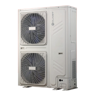
General information Description of system components Fig. 1 1 Air outlet 3 Refrigerant pipe connector (internal fitting) 2 Air inlets 4 Fixed stand WARNING The images in this manual are provided for illustrative purposes only. The appearance of your appliance may differ slightly from the illustrations shown here. - Page 9 General information Accessories The accessories are located at the top of the unit (e.g. the installation manual) or inside the unit, above the compressor (e.g. connecting pipe). The accessories in the unit are as follows: Description Aspect Quantity Drain fitting 120 Ohm termination heater Gasket Connection pipe (26/28/33.5kW)
- Page 10 Preliminary indications 2 PRELIMINARY INDICATIONS Combinations of outdoor/indoor units Indicated in the table are: – the maximum power obtainable (total power); – the maximum quantity of indoor units that can be installed in relation to the power of the outdoor unit installed (Max indoor units).
-
Page 11: Unit Dimensions
Preliminary indications Unit dimensions Operating range 200T - 224T - 252T - 260T - 335T The system is designed to function properly under the following climatic conditions: Relative indoor Outdoor Indoor Mode ambient temp. °C temp. °C humidity Cooling -5 to +55 * 17 to 32 <... - Page 12 Preliminary indications Length of refrigerant piping Installation with Outdoor units at the bottom In order to function correctly the system must take into account: – the total length of the pipes (1); – the maximum difference in height between the outdoor and indoor units (2) (3);...
-
Page 13: Installation
Installation 3 INSTALLATION Receiving the product The appliance is supplied packed. Handling must be carried out by appropriate means in view of the overall weight of the package. Preliminary warnings Upon receiving the appliance, check the perfect integrity of all parts. CAUTION Check that the model, specifications and quantity All installation operations must be carried out... - Page 14 Installation Handling Transport, lifting and handling must be carried out with all due care. Improper use and failure to comply with the instructions will void the warranty. WARNING As the unit’s centre of gravity is not the same as its physical centre, proceed with caution when lifting with straps.
- Page 15 Installation WARNING During all handling operations, use the > 300 mm appropriate PPE such as hard hat, gloves and > 600 > 600 safety shoes. > 3000 mm WARNING Before use, remove the pieces of PE foam in the Fig. 12 back of the unit that protect the condenser.
- Page 16 Installation In places with strong winds, provide windbreaks. > 600 mm Fig. 15 If the unit is installed in a place regularly exposed to Fig. 17 strong winds, such as on a building roof, make sure that the air outlet faces the wall. CAUTION Keep the unit at least 3000 mm away from the wall.
-
Page 17: Water Outlet
Installation Outlets for the connection pipes and (D) Depth of appliance (E) Location of holes on short side for the power supply line Water outlet Various possibilities are available for the passage of pipes and electrical cables: – Fit the gaskets (1) into the spaces in the frame (2). -
Page 18: Refrigerant Piping
Refrigerant piping 4 REFRIGERANT PIPING Keep the ends of the pipes sealed until installation to prevent the ingress of polluting agents such as dust, water and dirt. Installation of the refrigerant piping Below are the guidelines for compliant installation of the refrigerant piping ‰... - Page 19 Refrigerant piping Eliminate residual moisture lines. Welding must be done in a neutral atmosphere (nitrogen). Copper plating, formation of acid sludge, freezing of An inert atmosphere (free of moisture and oxygen) must the laminating devices, formation of acids that corrode be created inside the pipeline.
-
Page 20: Refrigerant Piping Connection
Refrigerant piping WARNING After connecting the pipes to the indoor and outdoor units, charge with pressurised nitrogen to perform a tightness test. 4.1.2 Connect the shut-off valves Stop valve The stop valves are closed when the unit is shipped from the factory. - Page 21 Refrigerant piping Use of the stop valve Closing of the stop valve 1 Remove the cover of the stop valve. 1 Remove the cover of the stop valve. 2 Insert the hexagonal wrench in the shut-off valve and 2 Insert the hexagonal wrench in the shut-off valve and turn the shut-off valve anti-clockwise.
- Page 22 Refrigerant piping 4.1.3 Sizing of the refrigerant piping Allowed value Piping Total length of pipes (Total extended length) 150 m +a+b+c+d+e+f Effective length ≤ 100 m Maximum pipe (first connection method) length (L) +f (second connection method) Equivalent length ≤ 110 m Pipe length Pipe length (between the furthest indoor unit +f (first connection method)
- Page 23 Refrigerant piping First connection method Outdoor unit first joint Indoor unit Fig. 31 Ref. Pipe length Value Ref. Description Maximum difference in height between Main pipe outdoor units (located at the top) and ..L Internal main pipes indoor units a ..
- Page 24 Refrigerant piping Second connection method Outdoor unit first joint Indoor unit Fig. 32 Ref. Pipe length Value Ref. Description Maximum difference in height between Main pipe outdoor units (located at the top) and ..L Internal main pipes indoor units a ..
- Page 25 Refrigerant piping The maximum length of the connection pipes between – Each internal auxiliary pipe must not be more than the branch joint and the furthest indoor unit must not 15m away from the internal branch joint (e.g. L and f) exceed 40m.
- Page 26 Refrigerant piping Selection of kits with main pipe (L1), internal main Selection of internal auxiliary pipes pipes (L2 to L5) and internal branch joint The internal auxiliary pipes (a...f) must respect the The dimensions of the main pipe and of the internal diameter indicated in the table, based on the overall main pipes are indicated in the following table.
- Page 27 Refrigerant piping EXAMPLE OF SIZING OF REFRIGERANT PIPING The example below illustrates the piping selection procedure for a system consisting of one outdoor unit (28kW) and 6 indoor units. The equivalent length of all the liquid pipes is greater than 90m; the pipe between the furthest indoor unit and the first junction of the indoor joints is less than 40m;...
- Page 28 Refrigerant piping Thermal insulation of the pipes Do not insulate the electrical cables (6) Insulate the refrigerant and gas piping separately with insulating polyethylene foam materials. Incorrect or missing insulation causes condensation and subsequent dripping. For the connection parts of the indoor unit piping, use heat-insulating materials that stick to the surfaces without leaving gaps.
- Page 29 Refrigerant piping Concealed internal wall Roof pipe Fig. 44 Fig. 40 Protections of parts that penetrate an area with External wall combustible material or a partition wall Fig. 41 External wall (exposed) Fig. 45 Insulating sheath 2 Insulating material 3 Coating 4 Grouting material 5 Tape 6 Waterproof layer...
-
Page 30: Electrical Connections
Electrical connections 5 ELECTRICAL CONNECTIONS CAUTION In order to remove the entire electrical panel: Preliminary information – empty the refrigeration circuit, taking care to recover the refrigerant; – desolder the pipe connected to the heat ATTENTION ELECTRIC DANGER sink which cools the electrical panel –... -
Page 31: Power Supply Line
Electrical connections The lower part of the clip (1) is fixed on the electrical panel, under the terminals. The upper part (2) is supplied CAUTION together with the other accessories. Secure the top with Equip each outdoor unit with an electrical the screws (3) supplied. - Page 32 Electrical connections Outdoor unit connections CAUTION Appliances in compliance with IEC 61000-3-12. The fixed wiring must incorporate an omnipolar switch where all active conductors have the minimum contact spacing required by national wiring regulations. ⏚ CAUTION Seal the electrical connections with insulating material to prevent condensate from forming.
- Page 33 Electrical connections How to connect the indoor unit – The cable used must be of a type suitable for data transmission with RS 485. If not suitable for such use it can cause interference and difficulties in the transmission of packets. –...
- Page 34 Electrical connections Outdoor unit connections Indoor unit connections 20 - 28 kW P Q (E) K1 K2 E P Q E ⏚ ⏚ ⏚ ⏚ Fig. 51 A Reserved B To the kilowatt/hour meter C To the main control board D Indoor unit communication bus Segnale (BUS) Signal (BUS)
-
Page 35: Wiring Method
Electrical connections Connect the various indoor and outdoor units as shown Do not connect two chains from a single outdoor unit. in the diagram below. P Q E P Q E P Q E P Q E P Q E P Q E P Q E P Q E... - Page 36 Electrical connections 230V~50Hz L2 L3 N K2 E O Y E P L N PE K1 K2 E 230V~50Hz L N PE X Y E L N PE O A E 230V~50Hz P Q E P Q E P Q E P Q E Fig.
- Page 37 Electrical connections Controller connection P Q E P Q E P Q E P Q E P Q E Fig. 59 A Outdoor unit B Indoor unit C Wired controller D Remote controller E Resistor - Add a resistor only at the P / Q end of the last indoor unit. CAUTION CAUTION Select the power supply source for the indoor...
-
Page 38: Starting Up The System
Starting up the system 6 STARTING UP THE SYSTEM Flushing the pipes The refrigerant piping must be flushed with nitrogen to remove dust, moisture and other particles that could cause the compressor to malfunction if not eliminated before the system is put into operation. Flushing should be carried out after completing connection of the piping, with the exception of final Fig. -
Page 39: Vacuum Operation
Starting up the system Vacuum operation Example: Initial room temperature (Ti) after charging with N2: 26°C Perform drying to remove moisture and non-condensable Nitrogen pressure (Pi) in the system at 26°C: 4.0 MPa (40bar) gases from the system. The elimination of moisture Final room temperature (Tf) after 24 hours: 18°C prevents the formation of ice and the oxidation of copper Nitrogen pressure (expected) at final room temperature (Tf) -
Page 40: Charging With Refrigerant
Starting up the system Charging with refrigerant CAUTION Charge the refrigerant only after having done “6.2 Gas leak test” page 38 and “6.3 Vacuum operation” page 39. CAUTION Do not charge more refrigerant than necessary because to do so can seriously compromise the correct functioning of the refrigeration circuit. - Page 41 Starting up the system The outdoor unit is supplied with a basic refrigerant charge. Factory pre-charge equivalent Model (kW) (kg) (tons) 20-28 13.57 33.5 16.71 An additional charge is required based on the length and diameter of the refrigerant line connecting the outdoor unit to the indoor units.
- Page 42 Starting up the system In case the refrigerant tank is insufficient for a complete Therefore, in the event of small leaks of refrigerant, R410A charge, close the three valves on the pressure gauge, can be treated in the same way as pure refrigerant R22, start the outdoor unit in cooling mode, then open (C) and (B).
- Page 43 Starting up the system Frequency of refrigerant leakage checks: – For appliances containing fluorinated greenhouse gases of 5 tons or more of equivalent CO2 but less than 50 tons of equivalent CO2, at least every 12 months or, where a leak detection system is installed, at least every 24 months.
-
Page 44: Special Functions
Special functions 7 SPECIAL FUNCTIONS 33.5 kW Mod. Configuration of the dip-switches CAUTION Disconnect power supply before configuring the dip switch The dip-switches can be configured in various ways at the switches on the main control board of the outdoor unit Dip-switch ON (1) Dip-switch OFF (0) 20/28.5 kW mod. - Page 45 Special functions 7.1.1 Error codes Code Description Phase protection Communication error between the indoor units and the master unit Temp.sensor T3 /room temp.sensor T4 error Voltage error DC fan motor error Drain temperature probe error TL sensor fault Error E6 twice in 10 minutes Communication error between the main control chip and the module chip Inverter module error...
-
Page 46: Start-Up Preparations
Start-up 8 START-UP 8.1.1 Checklist before running the test After installing the unit, first check the following points. After carrying out all the checks below, turn off the unit. Start-up preparations This is the only way to restart the unit. Carry out the following checks: After installation and configuration of the settings, the personnel must check that these have been carried... - Page 47 Start-up 8.1.2 Information on performing the test ‰ Installation data and field settings Make sure that the date of installation is recorded The following procedures relate to testing of the entire on the label of the electrical appliance and the system.
- Page 48 Start-up Commissioning Automatic addressing procedure for indoor units WARNING 1. Power off the ODU; It is necessary to fill in the commissioning report as a record the of operating status of 2. Leave power supplied all the IDUs; the system once the procedure is completed. 3.
-
Page 49: Maintenance
Maintenance 9 MAINTENANCE CAUTION It is good practice to periodically clean both the internal Do not insert fingers, sticks or other objects and external parts of the appliance. This guarantees its into the air inlet or outlet. Do not remove the proper operation and durability. - Page 50 Maintenance – The air conditioner does not switch on immediately Insufficient cooling or heating capacity. It can be after pressing the ON/OFF button on the remote caused: control; – by dirt in the heat exchanger; – If the operation light is on, the system is operating –...
- Page 51 Maintenance Maintenance after shutting the unit down for a long period For example, at the beginning of summer or winter. – Check and remove all the objects that could obstruct the air inlets and outlets of the indoor and outdoor units. –...
-
Page 52: Troubleshooting
Troubleshooting 10 TROUBLESHOOTING 10.1 Operating problems and possible causes If one of the malfunctions described below is encountered, switch off the air conditioner, disconnect it from the mains and contact an authorised technical service centre. – The operation light flashes quickly (twice per second). It continues flashing even if the unit is switched off and back on again. - Page 53 Troubleshooting 10.2 Remote control operating problems and possible causes Symptoms Causes Solution If automatic mode is selected, the air Check if the mode shown on the display conditioner automatically adjusts the fan is “AUTO”. speed. The fan speed cannot be If dry (dehumidification) mode is selected, adjusted.
- Page 54 Disposal 11 DISPOSAL The manufacturer is registered on the National EEE Professional WEEE: all WEEE which comes from Register, in compliance with implementation of Directive something other than private households. 2012/19/EU and pertinent national regulations on This equipment may contain: electrical and electronic equipment waste.
- Page 55 Disposal...
- Page 56 FOR 30 YEARS WE HAVE BEEN OFFERING SOLUTIONS FOR SUSTAINABLE COMFORT THE WELL-BEING OF PEOPLE AND THE ENVIRONMENT sales and service Info & Contacts: www.clivet.com...
Need help?
Do you have a question about the MSAN6-XMi 200T-335T Series and is the answer not in the manual?
Questions and answers