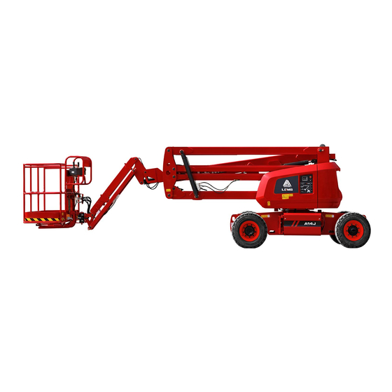
LGMG AR14J Service Manual
Articulated boom mobile elevating work platform
Hide thumbs
Also See for AR14J:
- Operation manual (73 pages) ,
- Maintenance manual (42 pages) ,
- Operation and safety manual (89 pages)
Table of Contents
Advertisement
Quick Links
Service Manual
AR14J/AR16J
Articulated Boom Mobile
Elevating Work Platform
△
WARNING
!
Before operation and maintenance, the
drivers and maintenance personnel are
required to read this manual thoroughly.
Otherwise, fatal accident may occur. This
manual shall be kept properly for future
reference by the personnel concerned.
LINGONG HEAVY MACHINERY CO., LTD.
Advertisement
Table of Contents

Related Manuals for LGMG AR14J


Summary of Contents for LGMG AR14J
- Page 1 Service Manual AR14J/AR16J Articulated Boom Mobile Elevating Work Platform △ WARNING Before operation and maintenance, the drivers and maintenance personnel are required to read this manual thoroughly. Otherwise, fatal accident may occur. This manual shall be kept properly for future reference by the personnel concerned.
- Page 2 L I N G O N G H E A V Y M A C H I N E R Y C O . , L T D . Add: F12,Building 3 LushangGuoao Plaza, 9777 Jingshi Road,Lixia District, Jinan, Shandong, 250000,China Tel: 86-0531-67605017 Technical service: 86-4009666569 Web: www.LGMG.com.cn Sales of accessories:86-0531-67605016...
-
Page 3: Table Of Contents
Chapter 2 Product Introduction ..............7 2.1 Parameters of machine ................. 9 2.1.1 Parameters of AR14J (A0014JNDCH20) articulated lifting platform ..... 9 2.1.2 Parameters of AR16J (A0016JNDCH20) articulated lifting platform ....13 2.2 Pressure parameters of filters and valves ........... 15 2.3 Tightening torque of joints and plugs ........... - Page 4 Service Manual of Articulated Boom Mobile Elevating Work Platform 3.3 Jib assembly ..................33 3.3.1 Disassembling the swing cylinder, the fly jib cylinder and the jib ......33 3.3.2 Assembling the swing cylinder, the fly jib cylinder and the jib ......35 3.4 Engine assembly .................
- Page 5 Service Manual of Articulated Boom Mobile Elevating Work Platform 3.10 Folding jib assembly ................70 3.10.1 Removing folding jib ..................71 3.10.2 Assembling folding jib assembly ............... 75 3.10.3 Removing folding jib lift cylinder ............... 77 3.10.4 Assembling folding jib lift cylinder ..............78 3.11 Rotary table swing assembly .............
- Page 6 6.2 Schematic diagram ................144 6.2.1 AR14J/AR16J hydraulic schematic diagram (Rexroth) ........144 6.2.2 AR14J/AR16J hydraulic schematic diagram (Sant main valve) ......145 6.2.3 AR14J/AR16J electrical schematic diagram (Rexroth) ........146 6.2.4 AR14J/AR16J electrical schematic diagram (Sant main valve) ......147 6.3 Diagram of common hydraulic part symbols ........
- Page 7 Mobile Elevating Work Platform Chapter 7 Kubota EU5 Engine Content ............. 176 7.1 Parameters of machine ..............178 7.1.1Parameters of AR14J(A0014JNKCH21)articulated lifting platform ....178 7.1.2 Parameters of AR16J(A0016JNKCH21) articulated lifting platform ....180 7.2 Kubota EUⅤ Engine assembly ............183 7.2.1 Subassembling the engine ................
-
Page 8: Foreword
Service Manual of Articulated Boom Mobile Elevating Work Platform Foreword Thanks for purchasing the product produced by Lingong Heavy Machinery Co., Ltd. This manual introduces the technical parameters and maintenance & adjustment data of the Articulated Boom Mobile Elevating Work Platform, and also the troubleshooting and maintenance process for reference by qualified professional maintenance personnel. -
Page 9: Safety Notices
Service Manual of Articulated Boom Mobile Elevating Work Platform Safety Notices The operator shall understand and abide by the current national and local safety regulations. If such regulations are not available, the safety instructions in this manual shall prevail. Most accidents are caused by failure to obey operation and maintenance specifications of the machine. - Page 10 Service Manual of Articulated Boom Mobile Elevating Work Platform...
-
Page 11: Chapter 1 Safety And Environment
Service Manual of Articulated Boom Mobile Elevating Work Platform Chapter 1 Safety and Environment... - Page 12 Service Manual of Articulated Boom Mobile Elevating Work Platform...
-
Page 13: Terms And Definitions
Service Manual of Articulated Boom Mobile Elevating Work Platform 1.1 Terms and definitions Administrator: the entity or individual that directly controls the use and application of the lifting platform, which usually refers to the owner, the renter or the authorized personnel of owner who obtains the control right of the lifting platform;... -
Page 14: Workplace Requirements
Service Manual of Articulated Boom Mobile Elevating Work Platform 1.4 Workplace requirements Unless specially specified, the machine shall be able to operate safely under the following conditions: Altitude ≤ 1000m; Ambient humidity ≤ 90% (at +25℃). The machine shall be able to operate normally under the following safe conditions: Ambient temperature of -20℃... - Page 15 Service Manual of Articulated Boom Mobile Elevating Work Platform Training of maintenance personnel: Maintenance personnel are required to be trained by qualified personnel, and then check and maintain the machine according to the requirements of this machine. 3. Replacement of parts The genuine parts of our company must be used for replacement;...
-
Page 16: Intended Use
Service Manual of Articulated Boom Mobile Elevating Work Platform 1.6 Intended use This machine is only intended for lifting people and their tools and materials to a high-altitude workplace. 1.7 Instructions Most maintenance processes can only be performed by professionally trained maintenance personnel in a properly equipped workshop. -
Page 17: Chapter 2 Product Introduction
Service Manual of Articulated Boom Mobile Elevating Work Platform Chapter 2 Product Introduction... - Page 18 Service Manual of Articulated Boom Mobile Elevating Work Platform...
-
Page 19: Parameters Of Machine
3. Turbo-worm slewing drive 4. 315/55 D20 filled off-road tire 4. 315/55 D20 filled off-road tire 5. COBO electronic control system 5. COBO electronic control system 2.1.1 Parameters of AR14J (A0014JNDCH20) articulated lifting platform 1) Parameters of machine Item Parameter Item... - Page 20 Service Manual of Articulated Boom Mobile Elevating Work Platform drive Along the boom 4.5° Front wheel Max. allowed inclination steering chassis Orthogonal 4.5° boom 2) Main dimensions Item Parameter Item Parameter Overall length (mm) 6766 Track width (mm) 1981.5 Overall width (mm) 2310 Wheelbase (front/rear) (mm) 2059...
- Page 21 Service Manual of Articulated Boom Mobile Elevating Work Platform Max. working pressure (MPa) Slewing system Motor displacement (ml/r) Steering Max. working pressure system (MPa) Φ90×Φ45-595-1135 Boom luffing cylinder (mm) Φ50×Φ32-1828-2122 Boom telescopic cylinder (mm) Φ75×Φ40-345-645 Up-and-down leveling cylinder (mm) Φ63×Φ45-670-924 Folding jib luffing cylinder (mm) Φ55×Φ35-436-789 Fly jib cylinder (mm)
- Page 22 Service Manual of Articulated Boom Mobile Elevating Work Platform -40℃< Min. temperature ≤-25℃: L-HS 32 ultra-low temperature hydraulic oil; Min. temperature ≤-40℃: 10# aviation hydraulic oil. Ambient temperature ≥ 4℃: 0# diesel; ambient temperature ≥ -5℃: -10# diesel; ambient temperature ≥- 14℃: -20 # diesel;...
-
Page 23: Parameters Of Ar16J (A0016Jndch20) Articulated Lifting Platform
Service Manual of Articulated Boom Mobile Elevating Work Platform 2.1.2 Parameters of AR16J (A0016JNDCH20) articulated lifting platform 1) Parameters of machine Item Parameter Item Parameter Rotary table rotation time per 82-92 circle (stowed) (s) Rated load (kg) Rotary table rotation time per 82-92 circle (extended) (s) Total weight (kg) - Page 24 Service Manual of Articulated Boom Mobile Elevating Work Platform Overall height (mm) 2170 Min. ground clearance (mm) Dimension of working platform 1830×760 Tire specification 315/55D20 (length × width) (mm) 3) Engine system Item Parameter Item Parameter Model Deutz D2.9L4 Number of cylinders In-line, water-cooled, Type Bore/stroke (mm)
-
Page 25: Pressure Parameters Of Filters And Valves
Service Manual of Articulated Boom Mobile Elevating Work Platform Φ50×Φ30-260-500 Steering cylinder (mm) Φ88.9-96-380 Floating cylinder (mm) 5) Transmission system Item Parameter Rated output torque 3500 (Nm) Walking reducer Speed ratio 57.49:1 Rated output torque 8729 Slewing reducer (Nm) Speed ratio 86:1 6) Electronic control system Item... -
Page 26: Tightening Torque Of Joints And Plugs
Service Manual of Articulated Boom Mobile Elevating Work Platform 4120704727 Check valve SY-RV-L15-M22*1.5-0.5 4120705965 Multi-way valve AR16JEDC-5 4120704690 Relief valve block 4120704392 6/2 electromagnetic switching valve 4120706178 Solenoid valve ST0010-AB0F 4120703874 Ball valve Q11F-16P-1'' 4120703386 Floating valve DCV20/1-0145 4120705600 Floating balance valve 4120707095 Platform swing control valve ST4277-AB00 4120704705... - Page 27 Service Manual of Articulated Boom Mobile Elevating Work Platform M16X1.5 G3/8A M18X1.5 G3/8A M20X1.5 G1/2A M22X1.5 G1/2A M27X2.0 G3/4A M33X2.0 M42X2.0 G11/4A M48X2.0 G11/2A Table 2: Tightening torque of UN-threaded joints and plugs (unit: N.m) Product series Thread UN/UNF Assembly torque with Assembly torque with direction unadjustable (N.m) direction unadjustable (N.m)
-
Page 28: Tightening Torque Of Nuts And Bolts
Service Manual of Articulated Boom Mobile Elevating Work Platform made of steel, and for connected part made of aluminum, the tightening torque equal to 60% of the corresponding torque in Table 2 and Table 3 shall apply and shall be rounded to the nearest integer after calculation;... - Page 29 Service Manual of Articulated Boom Mobile Elevating Work Platform Note: 1. For torques given in Table 2, an error of +10% is allowed; 2. The torque values given in Table 3 are based on the condition that the connected part is made of steel, and for connected part made of aluminum, the tightening torque equal to 60% of the corresponding torque in Table 1 shall apply and shall be rounded to the nearest integer after calculation;...
- Page 30 Service Manual of Articulated Boom Mobile Elevating Work Platform 12.9 1080 16~21 38~51 75~100 131~175 209~278 Nominal diameter of bolt, mm Bolt strength Yield strength, grade N/MM Tightening torque, N· m 90~110 120~150 170~210 230~290 300~377 110~140 150~190 210~270 290~350 370~450 145~193 199~264...
-
Page 31: Chapter 3 Maintenance
Service Manual of Articulated Boom Mobile Elevating Work Platform Chapter 3 Service... - Page 32 Service Manual of Articulated Boom Mobile Elevating Work Platform...
-
Page 33: Platform Assembly
Service Manual of Articulated Boom Mobile Elevating Work Platform 3.1 Platform assembly 3.1.2 Assembling the foot switch 3.1.1 Assembling the file box 1. Foot switch 2. Screw 3. Screw 4. Washer 1) Assemble part 1 with parts 2/3/4 to the assembling position at the bottom of the platform frame, and tighten the screws. -
Page 34: Assembling The Platform Support
Service Manual of Articulated Boom Mobile Elevating Work Platform platform in the same way as part 1. 3.1.5 Assembling the load cell Reference tightening torque of part 6: 12± 1N.m Tools: open-end wrench 13-16 3.1.4 Assembling the platform support 1. Load cell 2. Bolt 3. Washer 4. Nut 5. Triangular bracket assembly 6. -
Page 35: Assembling The Swing Motor Mounting Bracket
Service Manual of Articulated Boom Mobile Elevating Work Platform wrench 13-16 Tightening torque of part 5: 52± 5N.m Socket wrench 1/2-18mm, QSP100N4, S6 Tools: QSP100N4/socket wrench 1/2-16mm/ Allen wrench open-end wrench 13-16 3.1.6 Assembling the swing motor 3.1.7 Assembling the platform control mounting bracket unit (PCU) 1) Connect the triangular bracket assembly to... -
Page 36: Assembling The Platform
Service Manual of Articulated Boom Mobile Elevating Work Platform Reference tightening torque of part 2: QSP100N4 28± 3N.m 2) Connect the platform harness to PCU and Tools: 9-piece Allen wrench set/open-end connectors of load cell and platform valve block, wrench 13-16 and connect the corresponding oil pipes to the 3.1.9 Assembling the platform platform. -
Page 37: Assembling The Front Axle Assembly
Service Manual of Articulated Boom Mobile Elevating Work Platform supported, the chassis may fall. slowly to reduce the oil pressure gradually. Do not spray or eject the oil. 5) Unscrew the wheel nuts and remove the tires. 6) Remove the pipe clamp. 11) Remove the securing fastener of center shaft 7) Mark, disconnect and plug the hoses and for connecting the front axle to the chassis, and... - Page 38 Service Manual of Articulated Boom Mobile Elevating Work Platform be connected to the reducer in the same way. wrench S14 3) Lift the subassembled connecting plate to the assembly position of the front axle, and install part 1 to the upper and lower contact surfaces between the connecting plate and the front axle weldment.
- Page 39 Service Manual of Articulated Boom Mobile Elevating Work Platform with the non-rod piston chamber pulled out in the middle of front axle weldment. Then install washers (2504000277:4) on both upper and lower surfaces of the cylinder pin mounting hole, and install part 2 from top to bottom. Next, fix the 1.
-
Page 40: Disassembling The Rear Axle Assembly
Service Manual of Articulated Boom Mobile Elevating Work Platform 1. Axle connecting pin 2. Adjusting washer 3. 1. Lower pin of floating cylinder 2. Latch 3. Bolt Bolt 4. Washer 5. Latch 4. Washer Tightening torque of part 3: 52± 5N.m Tightening torque of part 3: 52±... -
Page 41: Assembling The Rear Axle Assembly
Service Manual of Articulated Boom Mobile Elevating Work Platform axle securely. supported correctly by the sling, the front axle may fall. 5) Mark, disconnect and plug the hoses and 3.2.4 Assembling the rear axle fittings connected to the rear axle walking motor, assembly as shown below: 1) Lift the rear axle weldment onto the... - Page 42 Service Manual of Articulated Boom Mobile Elevating Work Platform 2) Remove the plug (indicated by the illustrated 4 and 5 tightened to specified torque. See the yellow circle) of the subassembled rear axle figure below: motor, and lift the motor to the assembly position of the rear axle reducer.
-
Page 43: Disassembling The Wheel
Service Manual of Articulated Boom Mobile Elevating Work Platform washer 4. Bolt 5. Washer 3) Tighten all nuts to specified torque Tightening torque of part 4: 52± 5N.m diagonally. Tool: QSP100N4/ socket wrench 16 3.2.5 Disassembling the wheel 1) Unscrew the wheel nuts, but do not remove them . - Page 44 Service Manual of Articulated Boom Mobile Elevating Work Platform must be replaced. During installation, all the swing cylinder for the purpose of connections must be tightened to supporting. specified torque. Please refer to the 6) Remove the fastener of dowel pin from the specification for selection of tightening cylinder mounting shaft at the fly jib cylinder torque of the lifting platform.
-
Page 45: Assembling The Swing Cylinder, The Fly Jib Cylinder And The Jib
Service Manual of Articulated Boom Mobile Elevating Work Platform △ 12) Attach the sling from the overhead crane to WARNING: Risk of crushing the fly jib. If not properly supported by the crane, the 13) Use a suitable lifting device to support the jib may fall due to loss of balance during fly jib cylinder barrel end. - Page 46 Service Manual of Articulated Boom Mobile Elevating Work Platform 2) Connect the upper/lower connector (part 4). Then remove the attached plugs at assembly to the upper link with part 1, and then ports V1 and V2 of the balance valve, install the fix them with part 2/3/4/5, as shown below: straight fitting (part 3) to the two ports and tighten them to specified torque.
- Page 47 Service Manual of Articulated Boom Mobile Elevating Work Platform 1. Shaft 2. Latch 3. Bolt 4. Washer 5. Nut 6. Shaft 1. Shaft 2. Latch 3. Bolt 4. Washer 5. Nut 6. Shaft 7. Bolt 8) Install part 2/3 (coated with sealant)/ 4/5 for Tightening torque of part 3/7: 52±...
-
Page 48: Engine Assembly
Service Manual of Articulated Boom Mobile Elevating Work Platform Tools: Open-end wrench 13, ratchet wrench 10) Bundle up the platform control connecting wire and the fly jib valve block pipe at the illustrated position with the strap, and fix the pipe at the fly jib with part 1/2/3, as shown 1. - Page 49 Service Manual of Articulated Boom Mobile Elevating Work Platform 1. Flywheel coupling 2. Bolt 3. Washer 4. Pump 1. Right front outrigger 2. Left front outrigger 3. cover 5. Screw Intake steel pipe mounting bracket 4. Bolt 5. Tightening torque of part 2/5: 52± 5N.m Washer Tools: QSP100N4, socket wrench 16 Tightening torque of part 4: 90±...
- Page 50 Service Manual of Articulated Boom Mobile Elevating Work Platform Washer 5. Nut 6. Hoop 7. Electronic differential pressure alarm Tightening torque of part 2: 5-5.5N.m; Tightening torque of part 3: 28± 3N.m; Reference tightening torque of part 6: 15- 20N.m; Tools: 13mm socket wrench, 7mm socket 1.
-
Page 51: Assembling The Engine Cooling System
Service Manual of Articulated Boom Mobile Elevating Work Platform direction parallel to the axis of the engine to the radiator bracket. Note that part 7 needs muffler, as shown by the yellow arrows, with the to be added for the fixing bolt on the right rear U-bolt mount on the side away from the engine side of the radiator. -
Page 52: Assembling The Engine Fuel Pipeline
Service Manual of Articulated Boom Mobile Elevating Work Platform (part 2) and the washer (part 3). Install the flitch weldment onto the battery tray with the bolt (part 4), the washer for bolt (part 5), the washer for nut (part 6), and the nut (part 7). 1. - Page 53 Service Manual of Articulated Boom Mobile Elevating Work Platform 1. EFP mounting plate 2. Bolt 3. Nut 4. Washer the engine housing, and fasten the secondary 5. EFP 6. Bolt 7. Nut 8. Washer filter and the secondary filter cushion block with Tightening torque of part 6: 6±...
-
Page 54: Cable Carrier Assembly
Service Manual of Articulated Boom Mobile Elevating Work Platform Bolt 7. Washer Engine inlet pipe 4. Hose clamp 5. Bolt 6. Tightening torque of part 3/6: 32± 3N.m Washer Reference tightening torque of part 5: 2.5- Tightening torque of part 5: 32± 3N.m 3N.m Reference tightening torque of part 4: 2.5- Tools: QSP100N4, socket wrench 8/20/22,... - Page 55 Service Manual of Articulated Boom Mobile Elevating Work Platform 4) Remove the hose clamp on the boom head gradually. Do not spray or eject the oil. connecting plate. 9) Lift the boom to a horizontal position. 5) Pull out all cable harnesses from the cable 10) Place the cushion block between the upper carrier.
-
Page 56: Assembling The Cable Carrier
Service Manual of Articulated Boom Mobile Elevating Work Platform cylinder rod end with the copper hammer. unbalanced and fall. △ △ WARNING: Risk of crushing CAUTION: Risk of part damage If not properly supported by the lifting If being kinked or squeezed, the cable device, the boom luffing cylinder may harness and hose may be damaged. - Page 57 Service Manual of Articulated Boom Mobile Elevating Work Platform harnesses with 100mm long PVC (PVC ends 15± 2N.m Tool: 13mm open-end ratchet wrench are wrapped with black insulating tape) for 2) Arrange the oil pipes and harnesses under protection, as shown in the figure below: the support plate, then install clip rubber strips (with applied adhesive) at both ends of part 1, then fix part 1 with parts 2/3/4 (the insertion...
-
Page 58: Boom/Extension Jib Assembly
Service Manual of Articulated Boom Mobile Elevating Work Platform 3.6 Boom/extension jib assembly 3) Remove the cable carrier. Refer to "Disassembling the cable carrier". 3.6.1 Disassembling the boom △ 4) Lift the boom to a horizontal position. WARNING: Risk of personal injury 5) Remove the hose and cable cover from This procedure... -
Page 59: Assembling The Boom Assembly
Service Manual of Articulated Boom Mobile Elevating Work Platform extension pipe and move it away. cylinder to the support block. Protect the 12) Mark, disconnect and plug the hydraulic cylinder rod from damage. hose of the boom extension cylinder. And cover 19) Remove the fastener of dowel pin from the the fittings on the cylinder. - Page 60 Service Manual of Articulated Boom Mobile Elevating Work Platform gap between the inner surface of the latch Fig. 2 Fig. 1 Support pipe Support and the plate surface. beam 2) Install the travel switch (part 4) (1 piece) at Fig. 3 Fig.
-
Page 61: Disassembling The Extension Jib Assembly
Service Manual of Articulated Boom Mobile Elevating Work Platform 4. Travel switch 5. Screw 6. Nut 7. Washer 8. 2) Place the cushion block under the barrel end Boom luffing limit packing plate of the boom telescopic cylinder for support. Note: 3) Remove the fastener of dowel pin from the ①... -
Page 62: Assembling The Extension Jib Assembly
Service Manual of Articulated Boom Mobile Elevating Work Platform platform end of the telescopic boom. Knock out Washer the cylinder mounting shaft with a copper Tightening torque of part 4: 23± 2N.m; hammer. Tool: QSP50N3/socket wrench 16# 7) Support and slide the telescopic cylinder out Note: Ensure the balance of the workpiece of the bottom of the telescopic boom. - Page 63 Service Manual of Articulated Boom Mobile Elevating Work Platform As shown in the figure below, install the fixed end shown in the figure below: of the upper leveling cylinder from the front end of the extension jib: Part 1 Part 4/5 Part 3 Part 2 The assembled oil...
-
Page 64: Assembling The Telescopic Boom Assembly
Service Manual of Articulated Boom Mobile Elevating Work Platform 11) Adjust the shaft hole at the front end of the Note: After installation, the rear end of the cylinder, make it coaxial with the second group telescopic cylinder should go beyond the stop of holes at the front end of the extension jib block inside the rear end of the boom. -
Page 65: Hydraulic Tank/Fuel Tank
Service Manual of Articulated Boom Mobile Elevating Work Platform Screw Tool: QSP50N3/socket wrench 16# 3) Clamp the rear end of the telescopic cylinder 5) Install the telescopic balance valve assembly inside the stop block, and install the cylinder onto the fixed end of the telescopic cylinder pressure plate (part 1) onto the limit plate at the with part 3. - Page 66 Service Manual of Articulated Boom Mobile Elevating Work Platform 1. Air cleaner 2. Hydraulic tank weldment Tightening torque of part 4: 12± 1N.m; 3. Oil return filter element assembly 4. O- Tightening torque of part 5: 135± 14N.m; ring 5. Oil return flange assembly 6. Bolt Tightening torque of part 2: 220±...
-
Page 67: Disassembling The Hydraulic Tank
Service Manual of Articulated Boom Mobile Elevating Work Platform figure). hydraulic tank. △ CAUTION: Risk of part damage. The engine shall not be started when the valve of the hydraulic tank is closed, otherwise parts may be damaged. If the valve is closed, remove the key from the key switch and put a label on the machine to 1. -
Page 68: Assembling The Fuel Tank
Service Manual of Articulated Boom Mobile Elevating Work Platform machine. with parts 1/2. △ WARNING: Risk of crushing. If not properly supported and fixed on the lifting equipment during removal from the machine, the hydraulic tank may become unbalanced and fall. 1. -
Page 69: Cylinder Assembly
Service Manual of Articulated Boom Mobile Elevating Work Platform and return hoses. a suitable workshop. Carrying out this process without these skills and tools (2) Remove the fuel filler cap from the fuel tank. may result in death or serious injury, as (3) Remove the drain plug at the bottom of the well as serious component damage. -
Page 70: Assembling The Boom Luffing Cylinder
Service Manual of Articulated Boom Mobile Elevating Work Platform △ 6) Mark, disconnect and plug the hydraulic ! WARNING: Risk of crushing hose of the boom luffing cylinder. And cover the If not properly supported by the lifting fittings on the cylinder. device, the boom luffing cylinder may △... -
Page 71: Disassembling The Boom Telescopic Cylinder
Service Manual of Articulated Boom Mobile Elevating Work Platform Fig. 2 Fig. Left side Part Right 2. Shaft 3. Latch 4. Bolt 5. Washer side Tightening torque of part 20: 90± 9N.m; 1. Boom luffing cylinder Tool: QSP100N4/ socket wrench 18 Hoist the middle position of the cylinder, and pay 3.8.3 Disassembling the boom attention to the balance of the cylinder. - Page 72 Service Manual of Articulated Boom Mobile Elevating Work Platform fitting and/or hose assembly must be copper hammer. replaced. During installation, all 6) Remove the fastener of dowel pin of the connections must be tightened to cylinder mounting shaft at the barrel end. specified torque.
-
Page 73: Disassembling The Lower Leveling Cylinder
Service Manual of Articulated Boom Mobile Elevating Work Platform boom telescopic cylinder, refer to specification for selection of tightening Assembling the extension jib assembly. torque of the lifting platform. 3.8.4 Disassembling the lower leveling 1) Lift the folding jib until it can come into cylinder contact with the link end and barrel end pivots The lower leveling cylinder are in the same... -
Page 74: Assembling The Lower Leveling Cylinder
Service Manual of Articulated Boom Mobile Elevating Work Platform machine. leveling cylinder onto the upper pivot, with the oil △ port of the cylinder barrel facing down without WARNING: Risk of crushing reverse orientation; If not properly connected to the overhead ②... - Page 75 Service Manual of Articulated Boom Mobile Elevating Work Platform △ 2. The O-ring (if any) of the removed fitting or ! WARNING Risk of personal injury During hose assembly must be replaced. Sprayed hydraulic oil can penetrate and installation, all connections must be burn the skin.
-
Page 76: Bleeding Cylinder
Service Manual of Articulated Boom Mobile Elevating Work Platform △ ! CAUTION: Risk of part damage If the lifting equipment does not provide proper support and causes the slave leveling cylinder to fall, the cylinder may be damaged. Bleeding function pump 10) Knock out the pin at the barrel end with a 3.9.2 Bleeding slewing motor copper hammer;... -
Page 77: Bleeding Folding Jib Luffing Cylinder
Service Manual of Articulated Boom Mobile Elevating Work Platform cylinder can be divided into three parts, as 2) Activate the folding jib lifting button, and shown. The extension and retraction of piston operate the machine to retract and extend the rod should count as one cycle. -
Page 78: Bleeding Main Boom Telescopic Cylinder
Service Manual of Articulated Boom Mobile Elevating Work Platform reference, it can be divided into three parts, as 3.9.8 Bleeding fly jib luffing cylinder shown. Refer to "Bleeding folding jib luffing and upper leveling cylinder cylinder” for the bleeding steps and 1) Activate the fly jib luffing lifting button to bleed requirements. - Page 79 Service Manual of Articulated Boom Mobile Elevating Work Platform Bleeding platform swing cylinder...
-
Page 80: Folding Jib Assembly
Service Manual of Articulated Boom Mobile Elevating Work Platform 3.10 Folding jib assembly (1) Upper 2nd jib assembly (#1 (6) Folding jib cylinder jib) (7) Lower 2nd jib assembly (#4 (2) Upper 1st jib assembly (#2 jib) jib) (8) Rotary table assembly (3) Lower 1st jib assembly (#3 (9) Upper pivot jib) -
Page 81: Removing Folding Jib
Service Manual of Articulated Boom Mobile Elevating Work Platform △ 3.10.1 Removing folding jib ! WARNING: Risk of personal injury △ CAUTION: Risk of personal injury Spilled hydraulic oil can penetrate and This procedure requires specific service burn skin. Release the hydraulic device skills, lifting equipment and a suitable slowly to reduce the oil pressure workshop. - Page 82 Service Manual of Articulated Boom Mobile Elevating Work Platform pivot at the barrel end of the folding jib lift upper pivot for support. Do not lift it. cylinder. But do not remove the pin. 16) Connect the sling of another overhead 11) Tie the sling from the crane to the crane to the #1 jib midway between the connecting rod end of the folding jib lift cylinder...
- Page 83 Service Manual of Articulated Boom Mobile Elevating Work Platform Without proper support from 10×10×28cm cushion block. 10×10×28cm cushion block, the folding jib 29) Lower the #2 jib to the boom support pad. may fall. 22) Pull out all cables and hoses through the 30) Insert a 10×10×22cm cushion block at the upper pivot.
- Page 84 Service Manual of Articulated Boom Mobile Elevating Work Platform with a copper hammer. side. 38) Support the link with appropriate lifting 44) Remove the fuel tank filler cap. equipment. 45) Use an approved manual pump to drain 39) Remove the upper link shaft from the #2 jib the fuel in the fuel tank into a container with with a copper hammer.
-
Page 85: Assembling Folding Jib Assembly
Service Manual of Articulated Boom Mobile Elevating Work Platform tank and check for cracks and other 56) Remove the mounting fasteners of folding damage. jib drive speed limit switch from the #4 jib at the 48) Remove the securing fasteners from the middle shaft end. - Page 86 Service Manual of Articulated Boom Mobile Elevating Work Platform ② During lifting, no one shall stand in front of Fig. 2 the boom, the boom shall not pass directly above any personnel, and the operator shall stand at the oblique rear; The sling should be in 5) Lift the boom assembly to the rotary table, so...
-
Page 87: Removing Folding Jib Lift Cylinder
Service Manual of Articulated Boom Mobile Elevating Work Platform specification for selection of tightening in the following table. torque of the lifting platform. 6) Wrap the oil pipe arranged above the lower 1st jib assembly with the canvas (part 1), and 1) Lower the folding jib to the retracted position. -
Page 88: Assembling Folding Jib Lift Cylinder
Service Manual of Articulated Boom Mobile Elevating Work Platform Without proper connection to the overhead protrude from the right side of upper 2nd jib crane, the folding jib lift cylinder may fall due to assembly at this time; loss of balance during removal from the machine. △... -
Page 89: Rotary Table Swing Assembly
Service Manual of Articulated Boom Mobile Elevating Work Platform Tightening torque of part 6: 32± 3N.m; tightening torque of parts 7, 8 and 9: 75± 8N.m; Part 6 Tools: QSP50N3 / socket wrench 13/ socket Part 5 wrench 22 QSP100N4/SP120N*22 3.11 Rotary table swing assembly 5. -
Page 90: Assembling Slewing Drive Assembly
Service Manual of Articulated Boom Mobile Elevating Work Platform 2) Mark, disconnect and plug the hydraulic hose assembly tooling, and assemble the slewing of the rotary table slewing drive assembly. Plug drive assembly to the rotary table with parts 2 the fitting. -
Page 91: Assembling Tilt Sensor
Service Manual of Articulated Boom Mobile Elevating Work Platform threaded rod (part 3), washer (part 4) and nut switch. The tilt switch X is in the direction of the (part 5), and then tighten the nut. boom. Note: The removal is carried out in reverse order of assembly, and just corresponding fasteners need to be removed, which is not described in detail here. -
Page 92: Assembling Slewing Ring Grease Filler Hose
Service Manual of Articulated Boom Mobile Elevating Work Platform 3.12.4 Assembling slewing ring grease the grease filling machine until the grease filler hose overflows from the oil bowl slightly. Note: The removal is carried out in reverse order of assembly, and just corresponding fasteners need to be removed, which is not described in detail here. -
Page 93: Assembling Hydraulic Oil Radiator
Service Manual of Articulated Boom Mobile Elevating Work Platform not tighten the part 7. 2) Assemble part 1 to the ground control unit 3) Install the parts 5/6/8 (4120002548 fitting 2C- bracket weldment on the right side of the rotary 22-30 1) at the lower port and do not tighten the parts 6/8. -
Page 94: Valve Group
Service Manual of Articulated Boom Mobile Elevating Work Platform 3.13 Valve group 3.13.1 Multi-way valve assembly AR16JEDC-5 Name Function Oil inlet valve Oil inlet and return; connecting the valve block, pump and tank Luffing valve For luffing Coil Sandwich plate relief valve Secondary relief valve to protect oil cylinder Hexagon socket screw... -
Page 95: Platform Swing Control Valve St4277-Ab00
Service Manual of Articulated Boom Mobile Elevating Work Platform 3.13.2 Platform swing control valve ST4277-AB00 Mounting Name Code torque (N.M) Valve block ST4277-A000M 4120001998001 Solenoid valve SV08-31-0-N-0 4120001998002 Coil 4303612 4120001571010... -
Page 96: St5093-Ab0C Walking Control Valve Group
Service Manual of Articulated Boom Mobile Elevating Work Platform 3.13.3 ST5093-AB0C walking control valve group Name Code Spool function Valve block 4120704576003 Carrier of spool and ST5093-A000M oil passage Flow 4120001571002 Flow diversion and divider/combiner combination, FD56-45-0-P-66 increasing or decreasing fluid trend Flow 4120001571003... - Page 97 Service Manual of Articulated Boom Mobile Elevating Work Platform Check valve 4120704190002 Unidirectional oil CVC0.S10.0Y.000 flow Flush valve HS50- 4120001571007 Closed system flush 43-0-P valve Relief valve 4120001571008 Restricting flushing RVC0.S08.0Y.000 pressure Check valve 4120001490007 Unidirectional oil STCV08-0-000A flow Solenoid valve 4120001998002 2-speed, braking SV08-31-0-N-0...
- Page 98 Service Manual of Articulated Boom Mobile Elevating Work Platform...
-
Page 99: Chapter 4 Maintenance
Service Manual of Articulated Boom Mobile Elevating Work Platform Chapter 4 Maintenance... - Page 100 Service Manual of Articulated Boom Mobile Elevating Work Platform...
-
Page 101: Observing The Regulations
Service Manual of Articulated Boom Mobile Elevating Work Platform 4.1 Observing the regulations 4.2 Checking the battery The operator can only check the △ regular maintenance items specified in this ! Danger: Risk of explosion! Risk of manual. electric shock! Risk of burns! As required by the manufacturer, the Stay away from the fireworks, and remove regular maintenance and inspection shall be... -
Page 102: Checking The Hydraulic Filter
Check the color of the battery hydrometer: ! CAUTION: If an external power supply is required to charge the battery, only the charger approved by LGMG can be used. It is necessary to add the terminal Battery hydrometer protector and corrosion-resistant sealant... - Page 103 Service Manual of Articulated Boom Mobile Elevating Work Platform ⑤ Use a marker to write down the severe burns. △ replacement time and date on the filter element ! This step shall be implemented replacement record. when the engine is shut down. ⑥...
-
Page 104: Replacing The Air Filter Of The Hydraulic Tank
Service Manual of Articulated Boom Mobile Elevating Work Platform △ 4.4 Replacing the air filter of the ! If the hydraulic oil isn’t changed hydraulic tank during inspection in two years, it shall be The air filter of the hydraulic tank shall be checked on a quarterly basis. -
Page 105: Changing The Reducer Gear Oil
Service Manual of Articulated Boom Mobile Elevating Work Platform If the oil level of the reducer is incorrect, the to achieve superior performance and long performance of the machine will be service life of the equipment. If the reducer gear oil isn’t changed every year, the performance of deteriorated, and the parts will be damaged after continuous use. -
Page 106: Maintenance Of Worm-Type Slewing Drive
Grease grade: 3# grease Maintenance before delivery Position 2. Lubrication at the mesh between (Remarks: This refers to the lubrication of LGMG worm and slewing bearing. mobile elevating work platform before delivery) Lubrication amount: Appropriate Position 1. -
Page 107: Maintenance Of Deutz Engine
Service Manual of Articulated Boom Mobile Elevating Work Platform △ months or every 150h whichever comes first. ! No working on a running engine! No Lubrication method: While rotating smoking or open flames! Be careful when the slewing reducer, continuously add handling high temperature engine oil. -
Page 108: Changing Engine Oil And Replacing Oil Filter
Service Manual of Articulated Boom Mobile Elevating Work Platform is cold, check the oil level immediately. involved. Dry the wet parts with compressed air. △ ! Please abide by the oil safety provisions and local regulations. Dispose of spilled oil and filter elements as specified. - Page 109 Service Manual of Articulated Boom Mobile Elevating Work Platform into contact with high temperature engine oil and/or engine parts can cause serious burns. △ ! Perform this function after the engine warms up to normal operating temperature. Changing engine oil 1) Warm up the engine (oil temperature >...
-
Page 110: Checking Fuel Leaks
Service Manual of Articulated Boom Mobile Elevating Work Platform The leak shall be repaired immediately. 7) Secure the clamp of torsion stop (optional). 4.9.3 Checking fuel leaks 4.9.4 Bleeding or replacing the fuel △ filter ! Engine must be shut down! No △... - Page 111 Service Manual of Articulated Boom Mobile Elevating Work Platform △ 4. Drain the liquid until pure diesel flows out. ! Risk of explosion and fire. Fuel is 5. Install the drain plug and the electrical combustible. Check the location of the interface.
-
Page 112: Checking The Air Cleaner Of The Engine
Service Manual of Articulated Boom Mobile Elevating Work Platform 2. To ensure that no error message is sent, do cleaner element. not attempt to start the engine during bleeding. 3) Clean the air cleaner every 250h or quarterly, Perform the bleeding operation as follows: and replace the air cleaner every 1000h or 1. -
Page 113: Checking The Coolant Level
Service Manual of Articulated Boom Mobile Elevating Work Platform cleaning); replace the cleaner element Never run the engine without coolant, even when it is seriously contaminated. for a very short time. Replacing the air cleaner inner element 1) Carefully open the cover of the cooling △... -
Page 114: Checking The Engine Belt
Service Manual of Articulated Boom Mobile Elevating Work Platform 3) Check the radiator water pipe for scale. 2) Position the container under the coolant port. 4.9.9 Checking the engine belt Check the belt every 8h or everyday. 3) Drain the coolant. △... -
Page 115: Scheduled Maintenance
Service Manual of Articulated Boom Mobile Elevating Work Platform 1) Use a socket wrench to press the tensioner one. 4) Move the engine in the direction of (A) as arrowed until the locating pin can be fixed in the mounting hole. Then handle the until the correct belt tension is reached. -
Page 116: Fault Diagnosis Of Engine
Service Manual of Articulated Boom Mobile Elevating Work Platform 4.11 Fault diagnosis of engine Symptom Cause Action Coupling failure (if possible) Check the coupling No fuel in fuel tank Fuel tank The fuel inlet pipe is blocked Check Below the limit starting temperature Check Cold starter Check/replace... - Page 117 Service Manual of Articulated Boom Mobile Elevating Work Platform runs unstably or is Low compression force Check the compression force interrupted Cold starter Check/replace Air in the fuel system Bleed The primary fuel filter is dirty Clean The fuel quality is not as specified in the operation manual Change the fuel The injector is damaged...
- Page 118 Service Manual of Articulated Boom Mobile Elevating Work Platform The fan/viscous coupler is damaged, or the belt is torn or loosened Check/replace/tension The turbocharger air pipe is not tightly sealed Check the turbocharger air pipe The turbocharger air cooler is dirty Check/clean The air cleaner is dirty / the exhaust turbocharger is damaged...
- Page 119 Service Manual of Articulated Boom Mobile Elevating Work Platform necessary The turbocharger air pipe is not tightly sealed Check the turbocharger air pipe The turbocharger air cooler is dirty Clean The nozzle tube is not sealed Check the nozzle tube The injector is damaged Replace The throttle valve damaged...
- Page 120 Service Manual of Articulated Boom Mobile Elevating Work Platform The oil suction pipe is blocked Check/clean Check the oil level and drain the oil if The oil level is too high necessary Excessive engine oil Check engine mount / lower the tilt consumption The engine is tilted too a great extent position...
-
Page 121: Maintenance Schedule
Service Manual of Articulated Boom Mobile Elevating Work Platform The regeneration air cleaner is dirty / the exhaust turbocharger is damaged Check/replace The turbocharger air pipe is not tightly sealed Check the turbocharger air pipe The injector is damaged Replace The differential pressure flowmeter is damaged Replace Frequent stop... - Page 122 Service Manual of Articulated Boom Mobile Elevating Work Platform filter element walking pump 4120001427 Air cleaner EF2-32 Piece Hydraulic tank Return filter 4120000304 SJXHL-250*10 Piece element 5301000007 Gear oil SAE 85W/90 GL-5 Liter 2.72 Walking reducer: 0.68L×4 Cleaner outer Engine intake system (clean 4110001498004 P822768 Piece...
- Page 123 Service Manual of Articulated Boom Mobile Elevating Work Platform △ Note: The working hours are based on the engine working time, and the operation cycle is calculated from the date of production. Maintenance period Routine Level 5 Maintenance Level 2 Level 3 Level 4 inspectio...
- Page 124 Service Manual of Articulated Boom Mobile Elevating Work Platform fuel filter element (DeutzD2.9L4) or every six months, whichever comes first. Check the water level in the water separator, ● and drain the water regularly It can be Clean or replace the cleaned for air cleaner outer Clean the air cleaner outer element every 250h or when the indicator alarms,...
- Page 125 Service Manual of Articulated Boom Mobile Elevating Work Platform calibration Check if the system ● ● ● ● ● pressure is normal Check if the steering ● ● ● ● ● system pressure is normal Check if the traveling ● ●...
- Page 126 Service Manual of Articulated Boom Mobile Elevating Work Platform Check the machine bolts, nuts and other fasteners for Daily looseness or abnormal noise Check the structural parts of the machine Daily for cracks and if there is any open weld Check if the machine paint for falling off, Daily...
-
Page 127: Chapter 5 Commissioning
Service Manual of Articulated Boom Mobile Elevating Work Platform Chapter 5 Commissioning... - Page 128 Service Manual of Articulated Boom Mobile Elevating Work Platform...
-
Page 129: Safety Instructions
Service Manual of Articulated Boom Mobile Elevating Work Platform 5.1 Safety instructions people are not allowed to operate the machine during commissioning; Before commissioning, please make sure to 5) This machine is not insulated, and does not refer to the Operation and Maintenance Manual, provide protection against electric shock when familiarize yourself with the relevant safety it is in contact with or near wires, power... -
Page 130: Commissioning Process
Service Manual of Articulated Boom Mobile Elevating Work Platform 10. Do not sit, stand or climb on the protective 13.72 m 750V~1000KV guard of the platform. Stand steadily on the If the machine comes into contact with a live wire, platform base plate at all times. -
Page 131: Machine Inspection
Service Manual of Articulated Boom Mobile Elevating Work Platform button, ground control system switch, platform Drive enable function control switch, foot switch; Tilt sensor test Inspection criteria: effective in use. Gradeability test Visual inspection Curb test Check the appearance of the vehicle as follows: Pothole test 1) The top coat has no bumps, scratches, or Emergency function test... -
Page 132: Basic Test
Service Manual of Articulated Boom Mobile Elevating Work Platform criteria: 4≤A≤5mm upper and lower gaps of the boom Control criteria: F/G<1mm. Rear axle gap 2) Check the gap between the left and right covers and the counterweight Use a feeler to measure the gap between the left Gap between the slider and the boom 5.4 Basic test and right covers and the counterweight, and the... - Page 133 Service Manual of Articulated Boom Mobile Elevating Work Platform Ground control The engine cannot be started smoothly Emergency system panel stop switch without abnormal noise after the emergency stop Display Key switch switch of the ground control system is pressed Enable button Engine start...
-
Page 134: Basic Operation Test Of Ground Control Unit
Service Manual of Articulated Boom Mobile Elevating Work Platform and platform functions should not operate after level will drop if the platform leveling switch is each boom and platform function toggle switch moved downwards. is turned on. With the enable button held, all arm rods and Platform leveling platform functions should operate for a complete test... - Page 135 Service Manual of Articulated Boom Mobile Elevating Work Platform Short arm First arm rod lifting/lowering test lifting/lowering test 6) First arm rod extension and retraction 8) Second arm rod lift switch switch The second arm rod will rise if the second arm The arm rod will extend if the first arm rod rod lift switch is moved upwards;...
-
Page 136: Basic Operation Test Of Platform Control System
Service Manual of Articulated Boom Mobile Elevating Work Platform △ (2) The drive function shall not work with CAUTION: the auxiliary power supply. 1. Commissioning shall be done by a 5.4.3 Basic operation test of platform dedicated person, during control system commissioning period, no one else is 1) Start the machine and turn the key to the allowed to operate the machine. - Page 137 Service Manual of Articulated Boom Mobile Elevating Work Platform commissioning is visible to the naked eye, and it should be stopped when it is effective; 4) After the all commissioning operations are completed, the buttons and switches Foot switch shall be returned to their positions. 5) Press down the foot switch, and test the control lever or button of each function of the 8) Turn the key switch to the platform control...
- Page 138 Service Manual of Articulated Boom Mobile Elevating Work Platform Second arm rod lifting/lowering test 13) Control the rotation of the rotary table via the 11) Short arm lift switch left control lever. Control criteria: The short arm will rise if the short Control criteria: The rotary table will rotate to the arm lift switch is moved upwards;...
-
Page 139: Hydraulic Oil Level Test
Service Manual of Articulated Boom Mobile Elevating Work Platform the first arm rod extension and retraction switch modes, and the speed of the fly jib and platform is moved upwards. does not change. 16) Control the drive travel of the machine via 19) Drive speed selector switch the right control lever. -
Page 140: Load Test (1.1 Times Rated Load)
Service Manual of Articulated Boom Mobile Elevating Work Platform 2) After parking for 5 min, observe the oil level of the hydraulic tank. 5.4.6 Travel speed (high speed) test Control criteria: The amount of oil in the hydraulic 1) Press down the foot switch in the platform tank is higher than 1/3 of the scale of the level control mode;... -
Page 141: Braking Distance Test
Service Manual of Articulated Boom Mobile Elevating Work Platform record the time. Control criteria: 6.1± 0.5km/h, i.e. time: 10.9<t< 12.8 S Boom lifted 5.4.7 Braking distance test 90cm 1) Follow the travel speed test closely; 2) When the center of the front wheel of the 2) Adjust the traveling direction of the machine machine passes the 20m test line, turn off the to ensure that the machine is straightened and... -
Page 142: Braking Distance Test (At Slow Speed)
Service Manual of Articulated Boom Mobile Elevating Work Platform rods are retracted; 3. Pay attention to driving safety. 5.4.9 Braking distance test (at slow speed) Drive enable system test 1) Follow the travel speed (low speed) test 2) Adjust the arm rod to the retraction position, closely;... -
Page 143: Tilt Sensor Test
Service Manual of Articulated Boom Mobile Elevating Work Platform lever movement; functions are normal. 2. Pay attention to safety during the 5) In the platform control mode, depress the foot rotation test. switch, retract the boom, and repeat the above 5.4.11 Tilt sensor test 4.5°... -
Page 144: Gradeability Test (25%)
Service Manual of Articulated Boom Mobile Elevating Work Platform machine to the 25% slope. Control criteria: the machine climbs to the top normally, the tires do not slip and the machine does not tip over. 45% slope 5.4.14 Floating test 3) Adjust the platform height, and drive the 1) Start the machine, drive it to the front of 10cm machine to the 45% slope. - Page 145 Service Manual of Articulated Boom Mobile Elevating Work Platform is lifted to the highest position, stop lifting and Enable switch timing. Control criteria: 35s-45s. Rotary table rotary switch Ground control system panel 2) Press the enable button and rotary table rotary switch (to the left) at the same time, move First arm rod lifting/lowering test...
- Page 146 Service Manual of Articulated Boom Mobile Elevating Work Platform arm is lifted to the highest position, stop lifting and timing. Control criteria: 30S-50S. Short arm Second arm rod lifting/lowering test lifting/lowering test 7) Press the enable button and the first arm rod extension switch (leftward) at the same time to extend the boom and start timing simultaneously;...
-
Page 147: Lifting Height Test
Test target value of AR16J: 15.70 ± 0.16 (m); and platform controllers to “ON” position, turn the Test target value of AR14J: 14.09 ± 0.14 (m); key switch to “Ground control” position, and 3) Instructions for use of the laser range finder: operate the machine on the ground;... -
Page 148: Rated Load Calibration
Service Manual of Articulated Boom Mobile Elevating Work Platform harness incurs squeezing, wear, etc. 3) Hang the rated load of 230kg at the platform Control criteria: the machine has no oil leakage end, and calibrate the rated load. 5.5 Pressure test or structural interference, and the oil pipe harness is free of squeezing, wear, etc.;... - Page 149 Service Manual of Articulated Boom Mobile Elevating Work Platform counterclockwise with the Allen wrench to increase decrease pressure appropriate until the pressure is consistent with the target value; 5) Keep the position of the Allen wrench unchanged, and tighten the fastening nut of the relief valve;...
- Page 150 Service Manual of Articulated Boom Mobile Elevating Work Platform...
-
Page 151: Chapter 6 Appendix
Service Manual of Articulated Boom Mobile Elevating Work Platform Chapter 6 Appendix... - Page 152 Service Manual of Articulated Boom Mobile Elevating Work Platform...
-
Page 153: Dtcs Of Cobo System
Service Manual of Articulated Boom Mobile Elevating Work Platform 6.1 DTCs of COBO system Description Open circuit in control unit output power supply 1 Open circuit in control unit output power supply 2 Open circuit in control unit output power supply 34 Platform electric box extension module bus off Carrier electric box display bus off Weighing failure... -
Page 154: Schematic Diagram
Service Manual of Articulated Boom Mobile Elevating Work Platform 6.2 Schematic diagram 6.2.1 AR14J/AR16J hydraulic schematic diagram (Rexroth) -
Page 155: Ar14J/Ar16J Hydraulic Schematic Diagram (Sant Main Valve)
Service Manual of Articulated Boom Mobile Elevating Work Platform 6.2.2 AR14J/AR16J hydraulic schematic diagram (Sant main valve) -
Page 156: Ar14J/Ar16J Electrical Schematic Diagram (Rexroth)
Service Manual of Articulated Boom Mobile Elevating Work Platform 6.2.3 AR14J/AR16J electrical schematic diagram (Rexroth) -
Page 157: Ar14J/Ar16J Electrical Schematic Diagram (Sant Main Valve)
Service Manual of Articulated Boom Mobile Elevating Work Platform 6.2.4 AR14J/AR16J electrical schematic diagram (Sant main valve) -
Page 158: Diagram Of Common Hydraulic Part Symbols
Service Manual of Articulated Boom Mobile Elevating Work Platform 6.3 Diagram of common hydraulic part symbols Graphic symbols of common hydraulic parts (taken from GB/T786.1-1993) (1) Hydraulic pump, hydraulic motor and hydraulic cylinder Descripti Symbol Description Name Symbol Hydraulic General Detailed pump symbol... - Page 159 Service Manual of Articulated Boom Mobile Elevating Work Platform Hydraulic General Simplified motor symbol symbol One-way Unidirection fixed al flow, Detailed displaceme unidirection symbol nt hydraulic al rotation motor Adjustabl e two- Bidirectional bounce Two-way flow, cylinder fixed bidirectional Simplified displaceme rotation, symbol...
- Page 160 Service Manual of Articulated Boom Mobile Elevating Work Platform Unidirectio Fixed nal flow, displacem unidirection One-way al rotation, hydraulic action fixed pump - displaceme motor Pressur Turbochar Bidirection transduc Variable al flow, displacem bidirectiona l rotation, Continuo hydraulic variable us action pump - displaceme motor...
- Page 161 Service Manual of Articulated Boom Mobile Elevating Work Platform Detailed General symbol source symbol Single piston cylinder Simplified Energy Motor symbol source Double- acting cylinder Detailed Prime Except symbol motor motor Double piston cylinder Simplified symbol (2) Mechanical control devices and control methods Descriptio Descriptio Name...
- Page 162 Service Manual of Articulated Boom Mobile Elevating Work Platform Internal Ejector pressure control, type internal oil Hydraulic drain pilot depressuriza External tion control Variabl pressure e travel control control (with type remote relief outlet) Electromag net control, Spring- Electro- external Pilot controll hydraulic...
- Page 163 Service Manual of Articulated Boom Mobile Elevating Work Platform Electric al leads can be omitted, Manu Gener Single-acting and the electromagne oblique control symbol line can also face the lower right Double- Button acting type electromagne Single-acting Electric adjustable Manual electromagne control Draw...
- Page 164 Service Manual of Articulated Boom Mobile Elevating Work Platform One-way Feedbac General pedal type k control symbol Position detection by potentiomet Two-way Electrical Feedba ers, pedal type feedback differential control transformers method , etc. Follower Pressurizatio Internal valve n or mechani profiling depressurizat...
- Page 165 Service Manual of Articulated Boom Mobile Elevating Work Platform (3) Pressure control valve Descripti Descriptio Name Symbol Name Symbol General Pilot symbol proportion or spring Relief valve loaded solenoid type pressure relief reducing valve valve Proportio Pressur Pressure Pilot relief pressure reducing reducin...
- Page 166 Service Manual of Articulated Boom Mobile Elevating Work Platform General Direct- symbol Two- acting, Unloading externa direct- valve relief l oil acting valve drain unloadin g valve Genera Unloadi ng valve symbol Pressur Pilot direct- electromagne p1>p2 reducin acting tic unloading g valve pressur valve...
- Page 167 Service Manual of Articulated Boom Mobile Elevating Work Platform (4) Directional control valves Descriptio Descriptio Name Symbol Name Symbol Two- position Detailed five-way symbol hydraulic valve Check Check valve valve Simplified Two- symbol position (springs four-way can be motorize omitted) d valve Detailed Three-...
- Page 168 Service Manual of Articulated Boom Mobile Elevating Work Platform Simplifi Three- position symbol five-way (springs solenoid can be valve omitted) External control Double Three- hydraulica position internal four-way leakage controlled electro- (with check hydraulic manual valve valve emergenc y control device) Three- Throttle...
- Page 169 Service Manual of Articulated Boom Mobile Elevating Work Platform (5) Flow control valves Descripti Descripti Name Symbol Name Symbol Flow Detailed Simplifie regulating symbol d symbol valve Adjustab throttle valve Bypass Simplifie flow Simplifie d symbol d symbol regulating valve Flow regulati Temperatur...
- Page 170 Service Manual of Articulated Boom Mobile Elevating Work Platform Roller- controlled Flow throttle combiner valve valve (decelerati on valves) Synchroniz ation valve Flow Flow Flow Detailed regulatin regulating diverter/comb symbol g valve valve iner valve (6) Oil tanks Descript Descripti Name Symbol Name...
- Page 171 Service Manual of Articulated Boom Mobile Elevating Work Platform p1: Oil Gener Duplex inlet p2: Heater filter symb return Descripti Descripti Name Symbol Name Symbol Flow Pressure detector indicator (liquid flow indicator) Pressure gauge Flowmeter Flow detect (meter) Pressur Electric contact detecto pressure...
- Page 172 Service Manual of Articulated Boom Mobile Elevating Work Platform (9) Other auxiliary components Descriptio Descriptio Name Symbol Name Symbol Detailed Differential pressure symbol switch Pressure relay (pressure switch) General General Sensor symbol symbol Senso Detailed Pressure symbol sensor Travel switch General Temperatu symbol...
- Page 173 Service Manual of Articulated Boom Mobile Elevating Work Platform One- It can Control indicate a bleeder line drain line (pressur e tap) Quick Single- connecto r without rotary check connect valve Quick Rotary connect connect Quick Three- connecto r with rotary check connect...
-
Page 174: Diagram Of Common Electrical Part Symbols
Service Manual of Articulated Boom Mobile Elevating Work Platform 6.4 Diagram of common electrical part symbols Full list of graphic symbols: Graphic symbols Description Electrical graphic symbol of switch (mechanical) General symbol of multiple-pole switch in single-line representation General symbol of multiple-pole switch in multi-line representation Contactor (contact open at non-operating position) Contactor (contact closed at non-operating position) - Page 175 Service Manual of Articulated Boom Mobile Elevating Work Platform Drop-out fuse Fuse-switch Fuse-switch-disconnector Fuse type load switch Make contact, delayed closing when the operating device is actuated Make contact, delayed closing when the operating device is released Graphic symbol for electrical diagram of break contact, delayed closing when the operating device is released...
- Page 176 Service Manual of Articulated Boom Mobile Elevating Work Platform Break contact, delayed closing when the operating device is actuated Make contact, delayed closing when the operating device is actuated and delayed opening when the operating device is released Push button switch (unlocked) Knob switch, rotary switch (locked) Position switch, make contact Limit switch, make contact...
- Page 177 Service Manual of Articulated Boom Mobile Elevating Work Platform Make (normally open) contact Note: This symbol can also be used as a general symbol of switches Break (normally closed) contact Change-over break before make contact Passing make contact temporarily closed when the operating device is actuated or released Socket (female) or one pole of socket Plug (raised head) or one pole of plug...
- Page 178 Service Manual of Articulated Boom Mobile Elevating Work Platform Double winding transformer Three-winding transformer Autotransformer Reactor choke diagram Current transformer Pulse transformer Current transformer with two cores and two secondary windings Current transformer with two secondary windings on one core Three-phase, three-winding transformer with on-load tap-changer and star-delta connection of neutral lead Three-phase, three-winding transformer, in which two windings have...
- Page 179 Service Manual of Articulated Boom Mobile Elevating Work Platform Combined representation of operating device with two windings Operating device of thermal relay...
- Page 180 Service Manual of Articulated Boom Mobile Elevating Work Platform Gas relay Device for auto-reclosing General symbol of resistor Variable resistor Adjustable resistor Potentiometer with movable contact Preset potentiometer General symbol of capacitor Variable capacitor Adjustable capacitor Duplex homological variable capacitor Indicating instrument (the asterisk must have the specified meaning) Voltmeter...
- Page 181 Service Manual of Articulated Boom Mobile Elevating Work Platform Electrical graphic symbol of reactive-current meter Maximum demand indicator (operated by one integrating meter) Varmeter Power factor meter Frequency meter Thermometer, pyrometer (θ can be replaced by t) Tachometer Integrating meter, energy meter (the asterisk must be replaced as specified) Ampere-hour meter Energy meter (watt-hour meter)
- Page 182 Service Manual of Articulated Boom Mobile Elevating Work Platform Var-hour-meter Energy meter with transmitter Telemeter operated by energy meter (transponder) Telemeter with printing apparatus and operated by energy meter General symbols of screen, disk and rack Note: The equipment name can be indicated by equipment or models General symbol of column rack General symbols of manual switchboard, relay station, measurement console, business station, etc.
- Page 183 Service Manual of Articulated Boom Mobile Elevating Work Platform Primary cell pack or battery pack Tapped primary cell pack or battery pack General symbol of grounding Connected to housing or base plate Noiseless grounding Protective grounding Equipotential Cable terminal Straight junction box of power cable Connection box and distribution box of power cable...
- Page 184 Service Manual of Articulated Boom Mobile Elevating Work Platform Control and indicating equipment Alarm activation device (point type - manual or automatic) Line detector Fire alarm device Heat Smoke Explosive gas Manual start...
- Page 185 Service Manual of Articulated Boom Mobile Elevating Work Platform...
-
Page 186: Chapter 7 Kubota Eu5 Engine Content
Service Manual of Articulated Boom Mobile Elevating Work Platform Chapter 7 Kubota EU5 Engine Content... - Page 187 Service Manual of Articulated Boom Mobile Elevating Work Platform...
-
Page 188: Parameters Of Machine
Mobile Elevating Work Platform Notice: Chapter 7 is the differentiation content of Kubota EUⅤ engine and Deutz EUⅤ engine in AR14J\AR16J service manual.For other content of Kubota EUⅤ engine,please refer to the content of Deutz EUⅤ engine in the front of this manual. - Page 189 Service Manual of Articulated Boom Mobile Elevating Work Platform Climbing speed (stowed) >1.5 Max. allowed wind speed (m/s) 12.5 (km/h) Climbing speed Four-wheel ≤0.8 (extended) (km/h) drive Drive mode Maximum Along Front wheel 4.5° boom steering allowable inclination Boom 4.5° of chassis orthogonal Main dimensions...
-
Page 190: Parameters Of Ar16J(A0016Jnkch21) Articulated Lifting Platform
Service Manual of Articulated Boom Mobile Elevating Work Platform Steering Max. working pressure 23.5 system (MPa) Electronic control system Item Parameter Output voltage (V) Battery 120(20HR discharge rate) Capacity (Ah) Control system Voltage (V) Refilling capacity Item Parameter Item Parameter Hydraulic oil (L) Engine oil (L) 0.68*4... - Page 191 Service Manual of Articulated Boom Mobile Elevating Work Platform 2) Main dimensions Item Parameter Item Parameter 7560 1981.5 Overall length (mm) Wheelbase (mm) 2310 2059 Overall width (mm) Track width (mm) 2170 Overall height (mm) Min. ground clearance (mm) Dimension of working platform 1830×760 315/55D20 Tire specification...
- Page 192 Service Manual of Articulated Boom Mobile Elevating Work Platform Rated output torque Walking reducer (Nm) 120(20 小时放电率) Speed ratio Rated output torque Slewing reducer (Nm) Speed ratio 7) Refilling capacity Item Parameter Item Parameter Hydraulic oil (L) Engine oil (L) 0.68*4 Gearbox oil (L) Engine antifreeze (L)
-
Page 193: Kubota Euⅴ Engine Assembly
Service Manual of Articulated Boom Mobile Elevating Work Platform Tightening torque of part 2: 90± 9N.m 7.2 Kubota EUⅤ Engine assembly Tools: QSP100N4, socket wrench 21 7.2.1 Subassembling the engine 4)Assemble piece 1 to engine front right 1) Install part 1 to the engine with part 2 side with piece 3/4, Assemble piece 1 to (coated with sealant)/ 3, apply the sealant engine front left side with piece 3/4. -
Page 194: Assembling The Engine Cooling System
Service Manual of Articulated Boom Mobile Elevating Work Platform 7.2.2 Assembling the engine cooling with the engine air inlet hose and air filter; system Place a piece 8 rubber plate on the radiator bracket,place the piece 9 mounting plate on the rubber plate,place the piece 1 radiator assembly on the piece 9,connect the radiator assembly to the radiator bracket with the piece 5/10.One end... -
Page 195: Assembling The Engine Fuel Pipeline
Service Manual of Articulated Boom Mobile Elevating Work Platform 3) Install part 1 onto the engine tray with part end of the guard net in the front and rear directions should be within 18.5± 3mm. 2/3/4. Install the radiator flitch weldment (part 1) Fix part 5 onto part 1 with part 6/7/8. - Page 196 Service Manual of Articulated Boom Mobile Elevating Work Platform 10) One end of the fine filter inlet pipe is connected to the oil outlet of the fuel pump, and fixed with a collar.The other end is connected to the oil inlet of the fine filter and fixed.
-
Page 197: Kubota Euⅴengine Maintenance
Service Manual of Articulated Boom Mobile Elevating Work Platform Ⅴ required for machines with sealed or Kubota engine maintenance-free batteries. maintenance △ Warning: danger of electric shock. 7.3.1 Compliance and Obedience The operator is only allowed to perform Contact with an electrical circuit may routine maintenance items as specified in result in death or serious personal this manual. -
Page 198: Check Hydraulic Oil Level
△ Notice: It refers to the lubrication Model of the lubricating grease: 3# lubricating grease of the LGMG platform for working at Position III: Lubrication of the tapered roller heights before delivery. bearing: Position 1: Lubrication of the roller path: The... -
Page 199: Check For The Oil Level In The Reducer
Service Manual of Articulated Boom Mobile Elevating Work Platform hydraulic components may be damaged. Through daily inspections, the inspector can determine changes in the hydraulic oil level which can indicate problems with the hydraulic system. Make sure the boom is in the telescoped position and then visually check the hydraulic tank. -
Page 200: Replacement Of Engine Oil And Filter
Service Manual of Articulated Boom Mobile Elevating Work Platform other is at the top. △ Perform the function after engine Refill oil from the hole of reducer at the high point until the liquid level is the same as the warm up to normal operation side hole at the bottom. -
Page 201: Check For Fuel Leakage
Service Manual of Articulated Boom Mobile Elevating Work Platform necessary. Visually check for fuel leakage every 8 hours or every day. Replacement of the Engine Oil Filter △ The engine oil filter element must also be There is danger of explosion and replaced every time the engine oil is replaced. -
Page 202: Replacement Of The Fuel Filter
Service Manual of Articulated Boom Mobile Elevating Work Platform No smoking and open fires! Be careful when contacting high temperature fuel! △ Do not release the injection pipeline or the high-pressure oil pipeline when the engine is running. Figure 1-6 △... -
Page 203: Changing Of Oil Separator Element
Service Manual of Articulated Boom Mobile Elevating Work Platform easily accessible place. Fit a new oil separator element and gasket into position 7.3.12 Cleaning or Replacement of Air Filter Clean it every 250 hours or quarterly and replaced for every 1000 hours. △... -
Page 204: Check For Coolant Liquid Level
Service Manual of Articulated Boom Mobile Elevating Work Platform only if it is to be replaced. 2) Install the new Secondary element. To protect the engine, do not remove the 3) Install the filter element (4), place the outer secondary element in servicing the primary cover (2) and fix it with the hooking clip. -
Page 205: Check For Engine Belt
Service Manual of Articulated Boom Mobile Elevating Work Platform hot. When cool to the touch, rotate cap to the first 3) Reinstall the protector if necessary. stop to allow excess pressure to escape. 4) When it is a new belt, check whether the Then remove cap completely. -
Page 206: Kubota Euⅴ Engine Fault Table
Service Manual of Articulated Boom Mobile Elevating Work Platform 7.3.17 Kubota EUⅤ Engine fault table Fault Cause Measures Check the fuel tank, and remove water, dirt and other impurities. Fuel is thick and doesn't flow. Check the fuel filter cartridge and replace it if necessary. - Page 207 Service Manual of Articulated Boom Mobile Elevating Work Platform clearances within factory specs. Check the function of the relieve valve in the lubricating system. Check pressure switch. Check filter base gasket Engine warning lamp lights up. Consult your KUBOTA Dealer DPF service lamps light up Consult your KUBOTA Dealer Check oil level.
-
Page 208: Engine Fault Codes
Service Manual of Articulated Boom Mobile Elevating Work Platform 7.3.18 Engine fault codes DTC Description Inspection Item DTC Set Parameter Large phase shift between Phase difference (crankshaft position between NE pulse and NE-G Phase Shift sensor) pulse G pulse within +30 ~- (camshaft position sensor) 20°... - Page 209 Service Manual of Articulated Boom Mobile Elevating Work Platform Sensor: Low ground sensor voltage: below 0.176 V Coolant temperature Coolant Temperature Sensor/harness open sensor voltage: above Sensor: High shorted to +B 4.870 V Sensor/harness shorted to Rail pressure sensor Rail Pressure Sensor: Low ground;...
- Page 210 Service Manual of Articulated Boom Mobile Elevating Work Platform Glow plug relay coil Glow Heater Relay Drive Glow plug drive circuit resistance load Circuit Overheat overheat above specified value in ECU actuator open- 52357 EGR Actuator Open Circuit EGR actuator open circuit circuit error signal...
- Page 211 Service Manual of Articulated Boom Mobile Elevating Work Platform Error Injector charge voltage: Injector Charge Voltage: 52352 Injector charge voltage: low ECU charge circuit failure charge circuit failure SCV (MPROP) Open Circuit 1347 SCV open circuit SCV open circuit (MPROP) Drive SCV open or shorted to SCV open or shorted to...
- Page 212 Service Manual of Articulated Boom Mobile Elevating Work Platform 2: High outside sensor/harness sensor 2 voltage below 4.8V Accelerator position sensor Accelerator position Accelerator Position Sensor 52354 error signal (sensor/harness sensor error signal Error (CAN) open or shorted to ground, received via CAN etc.) Deviation...
- Page 213 Service Manual of Articulated Boom Mobile Elevating Work Platform DPF outlet temperature Exhaust Gas Temperature Sensor/harness shorted to 3246 sensor (T2) voltage: Sensor 2: Low ground below 0.08 V DPF outlet temperature Exhaust Gas Temperature Sensor/harness open 3246 sensor (T2) voltage: Sensor 2: High shorted to +B...
- Page 214 Service Manual of Articulated Boom Mobile Elevating Work Platform Simultaneous failure of all Simultaneous failure of Exhaust Temperature 52359 exhaust temperature all exhaust temperature Sensors Failure sensors sensors (sensor low) exhaust Emergency High temperatures (T0, T1 Temperature: 52360 Outputs exhaust and T2) reduced to Downstream Exhaust Gas temperature sensors 0, 1, 2...
-
Page 215: Kubota Euⅴ Schematic Diagram
Service Manual of Articulated Boom Mobile Elevating Work Platform 7.4 Kubota EUⅤ Schematic Diagram Electrical schematic diagram Hydraulic schematic diagram... - Page 216 Service Manual of Articulated Boom Mobile Elevating Work Platform...
Need help?
Do you have a question about the AR14J and is the answer not in the manual?
Questions and answers