Yamaha F150 Owner's Manual
Hide thumbs
Also See for F150:
- Owner's manual (234 pages) ,
- Maintenance manual (36 pages) ,
- Owner's manual (120 pages)

Related Manuals for Yamaha F150


Summary of Contents for Yamaha F150
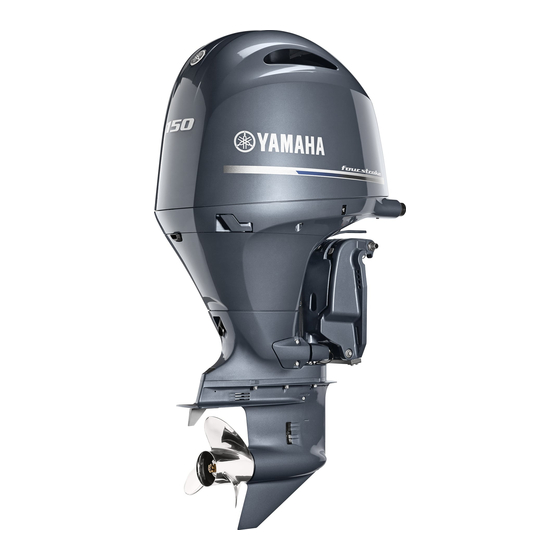
- Page 1 F150 LF150 F200 LF200 OWNER’S MANUAL Read this manual carefully before operating this outboard motor. 6LH-28199-70-E0...
- Page 2 Read this manual carefully before operating this outboard motor. Keep this manual onboard in a waterproof bag when boating. This manual should stay with the outboard motor if it is sold.
- Page 3 If EMU25108 To the owner there is any question concerning this manual, Thank you for selecting a Yamaha outboard please consult your Yamaha dealer. motor. This Owner’s Manual contains infor- To ensure long product life, Yamaha recom-...
-
Page 4: Table Of Contents
Warning labels ........7 Engine shut-off cord (lanyard) and Engine data recording..... 9 clip ..........29 6X6 switch ........29 Specifications and requirements... 11 Yamaha Security System Specifications........ 11 (Y-COP/Optional) ......29 Installation requirements....12 Main switch ........30 Boat horsepower rating....12 Start/Stop switch panel.... - Page 5 Table of contents All Start/Stop switch panel Installing top cowling ....... 49 (optional) ........31 Power trim and tilt system....51 Engine shut-off cord (lanyard) and Battery ..........51 clip ..........31 Filling fuel ........51 Outboard motor equipment ..32 Operating engine ......
- Page 6 Table of contents Cleaning the outboard motor ... 72 Checking painted surface of outboard motor......72 Periodic maintenance ....72 Replacement parts ......73 Severe operating conditions .... 73 Maintenance chart 1 ......74 Maintenance chart 2 ......77 Greasing ........... 78 Inspecting spark plug.......
-
Page 7: Safety Information
Safety information EMU33623 EMU33662 Outboard motor safety Power trim and tilt Body parts can be crushed between the mo- Observe these precautions at all times. tor and the clamp bracket when the motor is trimmed or tilted. Keep body parts out of this EMU36502 Propeller area at all times. -
Page 8: Gasoline
Have an approved PFD on board for every Gasoline exposure and spills Take care not to spill gasoline. If gasoline occupant. Yamaha recommends that you spills, wipe it up immediately with dry rags. must wear a PFD whenever boating. At a mi- Dispose of rags properly. -
Page 9: Overloading
Avoid sharp turns or other maneuvers that speed and have a Yamaha dealer inspect the make it hard for others to avoid you or un- outboard motor. derstand where you are going. -
Page 10: Weather
Safety information EMU33791 Weather Stay informed about the weather. Check weather forecasts before boating. Avoid boating in hazardous weather. EMU33881 Passenger training Make sure at least one other passenger is trained to operate the boat in the event of an emergency. -
Page 11: General Information
Record your outboard motor serial number in the spaces provided to assist you in ordering spare parts from your Yamaha dealer or for reference in case your outboard motor is sto- len. 1. Key number... -
Page 12: Compliance Mark Label
General information 1. Compliance mark label location 1. CE marking location Regulatory Compliance Mark (RCM) Engines affixed with this mark conform to certain portion(s) of the Australian Radio Communications Act. 0026 1521 6EE-43394-90 CE marking Outboard motors affixed with this “CE” mark- ZMU08190 conform with... -
Page 13: Read Manuals And Labels
Read any manuals supplied with the boat. Read all labels on the outboard motor and the boat. If you need any additional information, contact your Yamaha dealer. EMU33836 Warning labels If these labels are damaged or missing, contact your Yamaha dealer for replacements. - Page 14 General information 6EE-H1994-40 6EE-G2794-40 6EE-H1994-50 6EE-G2794-50 Attach engine shut-off cord (lanyard) to EMU34652 Contents of labels your PFD, arm, or leg so the engine The above warning labels mean as follows. stops if you accidentally leave the helm, which could prevent a runaway boat. EWM01682 EMU33851 Other labels...
-
Page 15: Engine Data Recording
Privacy Policy. Privacy Policy https://www.yamaha-motor.eu/eu/ privacy/privacy-policy.aspx Yamaha will not disclose this data to a third party except in the following cases. In addi- tion, Yamaha may provide engine data to a contractor in order to outsource services re- lated to the handling of the engine data. - Page 16 General information For use by Yamaha in litigation For general Yamaha-conducted research purposes when the data is not related to an individual engine or owner...
-
Page 17: Specifications And Requirements
Specifications and requirements Bore × stroke: EMU40501 Specifications 96.0 × 96.2 mm (3.78 × 3.79 in) TIP: Ignition system: “(SUS)” indicates that the specification is for the outboard motor when it is equipped with Spark plug (NGK): a stainless steel propeller. LFR6A-11 Spark plug gap: EMU48361... -
Page 18: Installation Requirements
Specifications and requirements Fuel and oil: Noise and vibration level: Operator sound pressure level (ICOMIA Recommended fuel: Premium unleaded gasoline (F200SA, 39/94): LF200SA) 78.8 dB(A) Regular unleaded gasoline (F150SA, EMU33556 Installation requirements LF150SA) Min. pump octane number (PON): EMU33566 86 (F150SA, LF150SA) Boat horsepower rating 89 (F200SA, LF200SA) EWM01561... -
Page 19: Battery Requirements
Perform setting of the outboard motor and The battery cable size and length are critical. the digital electronic control unit in the follow- Consult your Yamaha dealer about the bat- ing cases. tery cable size and length. If a used outboard motor is installed ... -
Page 20: Counter Rotation Models
Yamaha outboard motor and Standard outboard motors rotate clockwise. every application. Counter rotation models rotate counterclock- Your Yamaha dealer can help you select the wise and are typically used in multiple motor right propeller for your boating needs. Select setups. -
Page 21: Electro Hydraulic Steering Fluid Requirements
Specifications and requirements EMU49550 Recommended engine oil: Electro hydraulic steering fluid YAMALUBE 4 or 4-stroke outboard requirements motor oil Recommended engine oil grade 1: For the electro hydraulic steering fluid, use SAE 10W-30/10W-40/5W-30 the following recommended fluids. API SG/SH/SJ/SL Recommended engine oil grade 2: Recommended hydraulic steering SAE 15W-40/20W-40/20W-50 fluid 1:... -
Page 22: Muddy Or Acidic Water
Specifications and requirements EMU36881 Muddy or acidic water Yamaha strongly recommends that you have your dealer install the optional chromium- plated water pump kit if you use the outboard motor in muddy or acidic water conditions. However, depending on the model it might not be required. -
Page 23: Emission Control Information
MARINE ENGINES. REFER TO OWNER’S MANUAL FOR plugs. MAINTENANCE SPECIFICATIONS AND ADJUSTMENTS. FAMILY : EPA FEL : HC+NOx g/kW-h Consult your Yamaha dealer for details. MAX POWER : kW CA FEL : HC+NOx g/kW-h EMU39001 DISPLACEMENT: liters Emission control information... - Page 24 Specifications and requirements ZMU01702 ZMU01704 EMU40341 EMU33862 Two Stars—Very Low Emission Four Stars—Super Ultra Low Emission The two-star label identifies engines that The four-star label identifies engines that meet the Air Resources Board’s Personal meet the Air Resources Board’s Sterndrive Watercraft and Outboard marine engine 2004 and Inboard marine engine 2009 exhaust exhaust emission standards.
-
Page 25: Components
Components EMU48680 Components diagram TIP: * May not be exactly as shown; also may not be included as standard equipment on all models (order from dealer). 1. Top cowling 2. Cowling lock lever 3. Anti-cavitation plate 4. Cooling water inlet 5. - Page 26 Components 1. Oil dipstick 2. Fuel filter 3. Oil level plug 4. Gear oil drain screw 5. Oil filler cap 6. Fuse box 7. Power trim and tilt switch 8. Oil filter 9. Ignition coil...
-
Page 27: Optional Items
Components EMU46733 Optional items The following items are available from your Yamaha dealer. For details, consult your Yamaha dealer. MODE MODE 1. 6Y8 Multifunction tachometer 4. Yamaha Security System (Y-COP) 2. 6Y8 Multifunction speed & fuel meter 3. CL5 Display For single-engine boats (6X6 switch) 1. - Page 28 Components For single-engine boats (EKS) 1. Digital electronic control 4. Engine shut-off switch panel 2. POWER panel 3. Key fob For twin-engine boats (6X6 switch) 1. Digital electronic control (twin type) 4. All Start/Stop switch panel 2. Switch panel 3. Start/Stop switch panel For twin-engine boats (EKS) 1.
-
Page 29: Helm Master™ Ex (Upgradable)
TIP: control-alert indicator lights in blue and that For further information about the Helm Mas- the digital electronic control unit is correctly ter EX, consult your Yamaha dealer. connected to the outboard motor. Joystick TIP: Because the joystick allows you to move the ... -
Page 30: Control Lever
Components 6. Speed control switch 7. Power trim and tilt switch Twin engines 1. Power trim and tilt switch (starboard side engine) 2. Power trim and tilt switch (center engine) 3. Power trim and tilt switch (port side engine) TIP: The power trim and tilt switch of the center engine can be used to control triple engines. -
Page 31: Power Trim And Tilt Switches
A beep also sounds (repeated- ly on and off) to alert the operator. For more information, consult your Yamaha dealer. 1. Power trim and tilt switch... -
Page 32: Speed Control Switch
Components Single engine Twin engines 1. DEC alert indicator 1. Speed control switch Twin engines EMU48512 Neutral hold switch When the “NEUTRAL HOLD” switch is pressed, the buzzer will sound and the LED will come on. You will be able to open or close the throttle with the shift control in neu- tral. -
Page 33: Single Lever Switch
Components Twin engines EMU49271 Trim Assist switch This function automatically sets the outboard motor trim angle according to the engine speed. Enabling the trim assist switch allows the trim assist function to operate. TIP: For more information on the “Trim Assist” function, see the 6X9 DIGITAL ELECTRONIC CONTROL operation manual. -
Page 34: Electronic Key Switch (Eks)
Components Twin engines EMU48562 Electronic Key Switch (EKS) The EKS consists of the Electronic Key Switch panel and key fobs. TIP: This manual mainly covers basic operation. For more information, see the 6X9 DIGITAL ELECTRONIC CONTROL operation manual. EMU48572 Electronic Key Switch panel Pushing the “POWER”... -
Page 35: Engine Shut-Off Cord (Lanyard) And Clip
This will prevent the boat from ECM02461 running away under power. EWM01791 The Yamaha Security System is sold in conformity with the relevant laws and reg- Attach the engine shut-off cord to a se- ulations regarding radio wave transmis- cure place on your clothing, or your arm sion. -
Page 36: Main Switch
The Yamaha Security System, which pro- Single engine tects against theft, consists of the receiver and key fobs. The Yamaha Security System START is available from your Yamaha dealer. For de- tails, consult your Yamaha dealer. ZMU07145 Twin engines 1. Key fob 2. -
Page 37: All Start/Stop Switch Panel (Optional)
Components EWM01791 Attach the engine shut-off cord to a se- cure place on your clothing, or your arm or leg while operating. Do not attach the cord to clothing that could tear loose. Do not route the cord where it could become entangled, pre- venting it from functioning. -
Page 38: Outboard Motor Equipment
Components 1. Engine shut-off switch 1. Power trim and tilt switch 2. Clip 3. Engine shut-off cord (lanyard) EMU26246 Trim tab with anode EMU48651 Outboard motor equipment EWM00841 EMU26156 An improperly adjusted trim tab could Power trim and tilt switch on bottom cause difficult steering. -
Page 39: Tilt Support Lever For Power Trim And Tilt Model
Components 1. Cap 2. Bolt 3. Trim tab 1. Tilt support lever ECM00661 Do not use the tilt support lever or knob when trailering the boat. The outboard motor could shake loose from the tilt sup- ZMU07743 port and fall. If the motor cannot be Bolt tightening torque: trailered in the normal running position, 42 N·m (4.2 kgf·m, 31 lb·ft) -
Page 40: Flushing Device
Components EMU41312 Fuel filter The fuel filter functions to remove foreign ma- terial and separate water from the fuel. If wa- ter separated from the fuel exceeds a specific volume, the alert system will activate. For fur- ther information, see page 43. 1. -
Page 41: Instruments And Indicators
Engine condition icons If a warning message appears on the CL5 Orange icons indicate engine conditions. Display, follow the instructions on the dis- Yamaha Security System indicator “ ” play. (optional) TIP: This indicator appears when the Yamaha ... - Page 42 Stop the engine immedi- alert device has activated. Consult your ately and see page 97 of this manual to Yamaha dealer if the problem cannot be drain the water from the fuel filter. Consult located and corrected.
-
Page 43: 6Y8 Multifunction Meters
6Y8 Multifunction speed & fuel meter Alert “ ” If a malfunction occurs in the system, the system alert will be activated. Return to port immediately and contact your Yamaha dealer. EMU46654 6Y8 Multifunction meters There are two types of 6Y8 Multifunction me- MODE ters. - Page 44 Gasoline mixed with water could cause Yamaha Security System indicator (op- damage to the engine. tional) This indicator appears, when the Yamaha Se- Engine trouble-alert indicator curity System is in lock mode. If the engine malfunctions while cruising, the Lock mode engine trouble-alert indicator will start to blink.
- Page 45 Do not continue to operate the engine if an alert device has activated. Consult your Yamaha dealer if the problem can- not be located and corrected. Low oil pressure-alert indicator If the engine oil pressure drops too low, the...
-
Page 46: Engine Control System
DEC alert indicator will change from blue to orange. Even if there is no symp- tom of trouble with shifting or throttle, get back to port soon and have a Yamaha dealer inspect or repair the outboard motor. ZMU05422 ... - Page 47 Engine control system Illustration showing an example of the possible buzzer location START 1. Main switch If the alert system has activated, stop the en- gine and check the cooling water inlets. Check the trim angle to be sure that the cooling water inlets are submerged.
-
Page 48: Low Oil Pressure Alert
Check the oil level and add oil as needed. If the oil level is correct and the alert system does not turn ZMU05431 off, consult your Yamaha dealer. The pop-up window will appear on the Multiple-engine users Multi-Display. -
Page 49: Water Separator Alert
If the alert system has activated Stop the engine and see page 99 of this man- ual to drain the water from the fuel filter. Re- turn to port and consult a Yamaha dealer immediately. ECM02471 Although the buzzer will stop when the en- 1. -
Page 50: Installation
For twin engine boats, mount the outboard low, water resistance (drag) will increase, motors equidistant from the centerline. thereby reducing engine efficiency and per- Consult your Yamaha dealer or boat manu- formance. facturer for further information on determin- Most commonly, an outboard motor should ing the proper mounting location. - Page 51 Installation optimum mounting height. Consult your Yamaha dealer or boat manufacturer for fur- ther information on determining the proper mounting height. 1. Idle hole ECM01635 Make sure that the idle hole is high enough to prevent water from entering the engine even if the boat is stationary with the maximum load.
-
Page 52: Operation
Correct break-in will help en- The outboard motor is shipped from the fac- sure proper performance and longer engine tory without engine oil. If your Yamaha dealer life. NOTICE: Failure to follow the break-in did not fill the engine with engine oil, you procedure could result in reduced engine must fill the engine before starting it. -
Page 53: Checks Before Starting Engine
Operation EMU36414 2. Bottom cowling Checks before starting engine 3. Top cowling EWM01922 If any item in “Checks before starting en- gine” is not working properly, have it in- spected and repaired before operating the outboard motor. Otherwise, an accident could occur. -
Page 54: Controls
If any water is found in the fuel, or if a significant amount of debris is found, the fuel tank should be checked and cleaned by a Yamaha dealer. 1. DEC alert indicator (2) Turn the steering wheel fully to the left... -
Page 55: Outboard Motor
(4) Check that the oil level on the oil dipstick is between the upper and lower marks. Consult your Yamaha dealer if the oil lev- el is not at the proper level or if it appears 1. Fitting milky or dirty. - Page 56 Operation (3) Check that all of the cowling lock levers are pulled outward. (4) Align the 3 protrusions on the top cowl- ing with the corresponding holders on the bottom cowling, and then place the top cowling on the bottom cowling. 1.
-
Page 57: Power Trim And Tilt System
Body parts can be crushed between the If the battery needs charging, consult your motor and the clamp bracket when the Yamaha dealer or the battery manufacturer’s motor is trimmed or tilted. instructions. Be sure no one is near the outboard mo- EMU30028 tor before performing this check. -
Page 58: Operating Engine
If the buzzer sounds and the water EMU31814 separator-alert indicator blinks, consult a Sending fuel Yamaha dealer immediately. (1) If there is a fuel joint or a fuel valve on the EMU48603 boat, firmly connect the fuel line to the Procedure for single station models (EKS) joint or open the fuel valve. - Page 59 Operation Avoid accidentally pulling the cord dur- ing normal operation. Loss of engine power means the loss of most steering control. Also, without engine power, the boat could slow rapidly. This could cau- se people and objects in the boat to be thrown forward.
- Page 60 Yamaha dealer. (3) Attach the engine shut-off cord to a se- (5) The lock indicator turn off, and the cure place on your clothing, or your arm “POWER”...
- Page 61 Operation EMU48763 Procedure for single station models (6X6 switch) EWM01842 Failure to attach the engine shut-off cord could result in a runaway boat if operator is ejected. Attach the engine shut-off cord to a secure place on your clothing, or your arm or leg while oper- ating.
-
Page 62: Checks After Starting Engine
Operation (4) Turn the main switch to “ ” (start), When starting the engine using the All and hold it for a maximum of 5 seconds. Start/Stop button on the All Start/Stop NOTICE: Never turn the main switch switch panel, press the button to start to “... -
Page 63: Warming Up Engine
Stop the engine and check whether the cooling water inlet on the lower case or the cooling water pilot hole is blocked. Consult your Yamaha dealer if the problem cannot be located 1. Engine warm-up indicator and corrected. -
Page 64: Neutral Hold Switch Operation
Operation Warm up the engine before shifting into gear. (2) After the engine is at idle speed in gear, Until the engine is warm, the idle speed may move the remote control lever to the be higher than normal. The control lever of neutral position. -
Page 65: Single Lever Switch Operation
Operation (3) You can perform normal forward or re- 3. Starboard side engine verse operation To release EMU48720 (1) Place the control lever in “ ” (neutral). Single lever switch operation (2) When the “SINGLE LEVER” switch is TIP: pressed, a beep will sound and the LED ... -
Page 66: Procedure For Stopping Engine (6X6 Switch)
Operation (3) The lock indicator on the “POWER” switch turns on, and the system locks. 1. “START/STOP” switch (2) Press the “POWER” switch to turn off the 1. Lock indicator power. TIP: Only operates when the “POWER” switch is off. ... -
Page 67: Trimming Outboard Motor
Operation 1. Start/Stop button 1. Trim operating angle TIP: EMU27889 The engine can also be stopped by pulling Adjusting trim angle (Power trim and the cord and removing the clip from the en- tilt) gine shut-off switch, then turning the main EWM00754 switch to “... -
Page 68: Adjusting Boat Trim
Operation EMU27913 Adjusting boat trim When the boat is on plane, a bow-up attitude results in less drag, greater stability and effi- ciency. This is generally when the keel line of the boat is up about 3 to 5 degrees. With the bow up, the boat may have a greater tenden- cy to steer to one side or the other. -
Page 69: Tilting Up And Down
Operation Bow Down ECM00993 Too much trim-in causes the boat to “plow” Before tilting the outboard motor, follow through the water, decreasing fuel economy and making it hard to increase speed. Oper- the procedure under “Stopping engine” ating with excessive trim-in at higher speeds in this chapter. - Page 70 Operation (3) Set the tilt support lever to support the engine. WARNING! After tilting the out- board motor, be sure to support it with the tilt support knob or tilt support le- ver. Otherwise the outboard motor could fall back down suddenly if oil in the power trim and tilt unit or in the power tilt unit loses pressure.
-
Page 71: Procedure For Tilting Down
Operation EMU42703 Procedure for tilting down (1) Push the power trim and tilt switch “ ” (up) until the outboard motor is support- ed by the tilt rod and the tilt support lever becomes free. (2) Release the tilt support lever. 1. - Page 72 Operation Activating and deactivating the PTT To- talTilt function This function is deactivated by default. You can activate and deactivate it by yourself. EWM01544 Make sure that all people are clear of the outboard motor when tilting the outboard motor up and down. Body parts can be crushed between the outboard motor and the clamp bracket when the outboard mo- (5) Operate the trim zero set while keeping...
-
Page 73: Shallow Water
(2) Push the “ ” (up) side of the PTT switch If you suspect a malfunction, consult your twice quickly. Yamaha dealer. TIP: The PTT unit is stuck, or foreign matter is This operation causes the outboard motor preventing the tilting operation. -
Page 74: Cruising In Other Conditions
Cruising in muddy, turbid, or acidic water Yamaha strongly recommends that you use the optional chromium-plated water pump kit (see page 16) if you use the outboard motor in acidic water or water with a lot of sediment in it, such as muddy or turbid (cloudy) water. -
Page 75: Maintenance
It is advisable to have your outboard motor falls. serviced by an authorized Yamaha dealer pri- Do not use the tilt support lever or knob or to storage. However, you, the owner, with when trailering the boat. -
Page 76: Procedure
TIP: ler to prevent the propeller from turning. A flushing attachment is available from your Yamaha dealer. Cooling system flushing is essential to pre- (5) Run the engine at a fast idle for a few mi- vent the cooling system from clogging up nutes in neutral while supplying fresh wa- with salt, sand, or dirt. -
Page 77: Lubrication
Maintenance ing, return the main switch to “ ” Seal replacement should be performed (on), wait 10 seconds, then crank the by an authorized Yamaha dealer prior to engine again. use. [ECM00193] (2) Lubricate all grease fittings. For further TIP: details, see page 78. -
Page 78: Cleaning The Outboard Motor
When flushing the cooling water passages perform a maintenance procedure, have a with the boat in the water, tilting the outboard Yamaha dealer or other qualified mechan- motor up until it is completely out of the water ic do the work. -
Page 79: Replacement Parts
Yamaha marine dealership. EMU28512 Replacement parts If replacement parts are necessary, use only genuine Yamaha parts or parts of equivalent design and quality. Any part of inferior quality may malfunction, and the resulting loss of control could endanger the operator and pas- sengers. -
Page 80: Maintenance Chart 1
When operating in salt water, muddy, other turbid (cloudy), acidic water, the engine should be flushed with clean water after each use. The “ ” symbol indicates the check-ups which you may carry out yourself. The “ ” symbol indicates work to be carried out by your Yamaha dealer. Initial Every... - Page 81 Maintenance Initial Every 20 hours Item Actions Page 100 hours 300 hours 500 hours (1 year) (3 years) (5 years) months) Inspection or re- Fuel filter (can be placement as nec- disassembled) essary Fuel line (High Inspection — pressure) Inspection or re- Fuel line (High placement as nec- —...
- Page 82 — switch essary Wire harness con- Inspection or re- nections/wire cou- placement as nec- — pler connections essary (Yamaha) Me- Inspection — ter/gauge Inspection or re- Electro-Hydraulic placement as nec- — Steering system essary EMU46050 *1 exhaust cover...
-
Page 83: Maintenance Chart 2
Maintenance EMU46083 Maintenance chart 2 Every Item Actions Page 1000 hours Inspection or re- Exhaust guide/ex- placement as nec- — haust manifold essary Timing belt Replacement — Inspection or re- Electro-Hydraulic placement as nec- — Steering system essary... -
Page 84: Greasing
Maintenance EMU28946 Greasing Yamalube grease A (water resistant grease) Yamaha grease D (corrosion resistant grease; for propeller shaft) - Page 85 Maintenance...
-
Page 86: Inspecting Spark Plug
Do not attempt to diagnose any problems yourself. Instead, take the out- board motor to a Yamaha dealer. You should periodically remove and check the spark plug because heat and deposits will cause the spark plug to slowly break down and erode. -
Page 87: Inspecting Engine Idle Speed
(2) Inspect the engine idle speed. If the en- 2. Spark plug part number gine idle speed is out of specification, 3. Spark plug I.D. mark (NGK) consult a Yamaha dealer or other quali- fied mechanic. Spark plug gap: 1.0–1.1 mm (0.039–0.043 in) Idle speed (in neutral): 650–750 r/min... - Page 88 If you are not familiar with the proce- dure for changing the engine oil, consult your Yamaha dealer. Changing the engine oil using an oil changer (recommended) 1. Oil filler cap (1) Put the outboard motor in an upright po- sition (not tilted).
- Page 89 For more information on the disposal of (10) Remove the oil dipstick and wipe it used oil, consult your Yamaha dealer. clean. Change the oil more often when operating (11) Insert the dipstick and remove it again.
- Page 90 Maintenance 1. Oil filler cap (2) Start the engine. Warm it up and keep (7) Prepare a suitable container that holds a the idle speed for 5-10 minutes. larger amount than the engine oil capac- (3) Stop the engine and leave it for 5-10 mi- ity.
- Page 91 (8) Put a new gasket on the drain screw. Ap- and lower marks. Consult your Yamaha ply a light coat of oil to the gasket and in- dealer if the oil level is out of specified stall the drain screw.
-
Page 92: Replacing The Engine Oil Filter
(5) Turn the engine oil filter clockwise and tighten it to the specified torque. stand. Yamaha recommends you to have a Yamaha dealer replace the engine oil filter. If you perform replacement yourself, follow the procedure below. If you have any ques- tions, please consult a Yamaha dealer. -
Page 93: Inspecting Wiring And Connectors
” (off) position, into oil since the 1960’s helps make remove the key, and remove the clip from Yamalube the best choice for your Yamaha the engine shut-off switch. Turn off the engine. battery cut-off switch if your boat has one. -
Page 94: Removing Propeller
Maintenance EMU41963 Installing propeller EWM00771 On counter rotation models, be sure to use a propeller intended for counterclock- wise rotation. These propellers are identi- fied with the letter “L” after the size indication on the propeller. Otherwise the boat could move in the opposite direction from that expected. -
Page 95: Changing Gear Oil
Have a fastened to the transom or a stable Yamaha dealer check and repair the stand. You could be severely injured if outboard motor. the outboard motor falls on you. -
Page 96: Inspecting And Replacing Anode(S)
EMU29318 5 / SAE 90 API GL-5 Inspecting and replacing anode(s) Gear oil quantity: Yamaha outboard motors are protected from 0.980 L (1.036 US qt, 0.862 Imp.qt) corrosion by sacrificial anodes. Inspect the external anodes periodically. Remove scales from the surfaces of the anodes. Consult a Yamaha dealer for replacement of external anodes. -
Page 97: Checking Battery (For Electric Start Models)
Consult a functions will help you monitor the bat- Yamaha dealer for inspection and replace- tery’s charge. If the battery needs charg- ment of internal anodes attached to the pow- ing, consult your Yamaha dealer. - Page 98 6. Battery for starting If connecting an accessory battery, consult 7. Negative connecting cable your Yamaha dealer about correct wiring. It is recommendable to install the fuse to the iso- lator lead as shown in the illustration. For the fuse size, be sure to follow local regulations.
-
Page 99: Disconnecting The Battery
EMU38661 Storing the battery When storing your Yamaha outboard motor for prolonged periods of time (2 months or longer), remove the battery and store it in a cool, dry place. Check the battery and charge it if necessary. -
Page 100: Trouble Recovery
If the engine trouble-alert indicator is blinking, consult your Yamaha dealer. Q. Is fuel pump malfunctioning? A. Have serviced by a Yamaha dealer. Starter will not operate. Q. Does the DEC alert indicator come on in Q. Are spark plugs fouled or of incorrect ty- orange? A. - Page 101 Q. Is low oil pressure-alert indicator on or blinking? Q. Are ignition parts malfunctioning? A. Have serviced by a Yamaha dealer. A. Have serviced by a Yamaha dealer. Q. Is heat range of spark plugs incorrect? Q. Has alert system activated? A.
- Page 102 Yamaha dealer. Q. Is outboard motor mounted at incorrect Q. Are electrical parts malfunctioning? height on transom? A. Have serviced by a Yamaha dealer. A. Have outboard motor adjusted to proper transom height. Q. Is specified fuel not being used? A.
-
Page 103: Temporary Action In Emergency
Trouble Recovery Q. Are weeds or other foreign material tan- (4) Have a Yamaha dealer check the out- gled on propeller? board motor before operating it again. A. Remove and clean propeller. EMU29454 Running single engine (twin engines) Q. Are outboard motor mounting bolts loose? When using only one engine in an emergen- A. -
Page 104: Power Trim And Tilt Will Not Operate
Install a spare fuse of the proper amperage, and then tighten the screws. ZMU04337 1. Fuse puller Consult your Yamaha dealer if the new fuse 1. Fuse box cover immediately blows again. 2. Spare fuse (10 A, 15 A, 20 A, 30 A, 60 A, 70 3. -
Page 105: Electro-Hydraulic Steering System Will Not Operate
Trouble Recovery 1. Manual valve screw 1. Manual valve screw (3) Steer the outboard motor manually. (3) Adjust the outboard motor to a navigable (4) Tighten the manual valve screw until it angle, tighten the manual valve screw stops. clockwise, and secure the outboard mo- tor. -
Page 106: Treatment Of Submerged Motor
2. O-ring If the outboard motor is submerged, immedi- 3. Filter cup ately take it to a Yamaha dealer. Otherwise 4. Water detection switch lead some corrosion may begin almost immedi- (5) Drain the water in the filter cup by soak- ately. -
Page 107: Index
INDEX 6X6 switch ..........29 6Y8 Multifunction meters...... 37 DEC alert indicator........ 25 Digital electronic control ....... 23 Digital electronic control alert ....40 Digital electronic control Alcohol and drugs........2 requirements ........12 Alert system.......... 40 All Start/Stop switch panel (optional) ... 31 Anode(s), inspecting and replacing .. - Page 108 INDEX Outboard motor (painted surface), checking ..........72 Gasoline..........2, 15 Outboard motor safety ......1 Gasoline exposure and spills....2 Outboard motor serial number ....5 Gear oil, changing......... 89 Overheat alert ........40 Greasing ..........78 Overloading ..........3 Helm Master EX (upgradable)....
- Page 109 Troubleshooting........94 Warming up engine ......57 Warning labels ........7 Water separator alert ......43 Water separator-alert is activated after leaving port ........ 99 Weather ..........4 Wiring and connectors, inspecting..87 Yamaha Security System (Y-COP/Optional) ....... 29 Yamalube..........86...
- Page 110 Printed in Japan December 2022–0.3 × 1 CR...
Need help?
Do you have a question about the F150 and is the answer not in the manual?
Questions and answers