Sony PCS-11 Operating Instructions Manual
Hide thumbs
Also See for PCS-11:
- Operation manual (156 pages) ,
- Operation manual (13 pages) ,
- Operation manual (2 pages)

Related Manuals for Sony PCS-11


Summary of Contents for Sony PCS-11
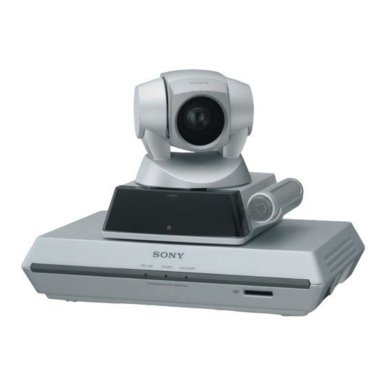
- Page 1 3-826-978-18 (1) Video Communication System Operating Instructions (Version 3.2) Before operating the unit, please read this manual thoroughly and retain it for future reference. PCS-11/11P © 2004 Sony Corporation...
- Page 2 This manual focuses on using ISDN lines to conduct a videoconference, but it also covers non-ISDN lines. If you use ISDN lines, consult your Sony dealer for more information. • The ISDN service may not be available in some areas.
- Page 3 In the case that interference should occur, consult your nearest authorized Sony service facility. Voor de klanten in Nederland Dit apparaat bevat een vast ingebouwde batterij die niet vervangen hoeft te worden tijdens de levensduur van het apparaat.
-
Page 4: Table Of Contents
Table of Contents Chapter 1: Installation and Preparation Using This Manual ....................10 Features ........................11 System Components ....................13 Basic System Components .................13 Optional Equipment ...................14 System Configuration ....................16 System Configuration via a LAN ...............16 System Configuration via an ISDN ..............17 System Connections ....................18 System Connection via a LAN ................18 System Connection via an ISDN ................19 Preparing the System ....................20... - Page 5 Chapter 2: Registration and Setup for System Administrators Registering Local Information ................35 Opening the Setup Menu for the Administrator ..........35 Dial Setup Menu ....................36 Answer Setup Menu ..................39 General Setup Menu ..................41 Audio Setup Menu ..................... 44 LAN Setup Menu ....................
- Page 6 Calling a Remote Party ..................76 Receiving a Call from a Remote Party ..............83 Answering a Call from a Remote Party .............83 Ending the Conference ..................85 Adjusting the Sound ....................86 Adjusting the Volume ..................86 Cutting Off the Sound Momentarily – Muting Function ........86 Cutting Off the Sound On Answering –...
- Page 7 Preparing for an Encrypted Videoconference ............136 Starting an Encrypted Videoconference ............... 138 Chapter 6: Multipoint Videoconference Connecting Other Sony Video Communication System With the MCU Software Installed ......................... 140 Switching the Broadcast Mode ................ 141 Connecting the External MCU ................142...
- Page 8 Select a Tool ......................160 How to Use “Controller” ..................161 To Control the PCS-11/11P from the On-screen Controller ......161 To Control the PCS-11/11P from the On-screen Remote Commander ...162 How to Use “Dial/Disconnect” ................163 How to Use “Phone Book” ..................164 “Phone Book-Edit” Page ..................165 “Phone Book-New”...
- Page 9 PCSA-B768S/PCS-B768 ISDN Unit (Optional) ..........197 Pin Assignment ....................197 Pin Assignment on Optional Board Connectors ..........198 List of Port Numbers Used on the PCS-11/11P ..........199 Videoconferencing Room Layout ................. 200 Camera Range ....................200 Installing the Communication Terminal and Camera ........202 Glossary ........................
-
Page 10: Chapter 1: Installation And Preparation
This chapter shows you how to control the use your Video Communication System for PCS-11/11P or set it up via a Web browser. the first time. It shows you how to install and connect your Video Communication... -
Page 11: Features
ISDN unit. encrypted videoconference between two points is available via ISDN and/or LAN. Wide range of video/audio When using Sony encryption, an encrypted compression formats selectable videoconference between two points is The Video Communication System supports available via LAN or SIP. - Page 12 During a conference using SIP, you can put a call on hold or transfer it to another remote party following procedures similar to those of an IP phone. Features...
-
Page 13: System Components
The PCS-11/11P Video Communication System is composed of basic system components for a basic videoconference, and optional equipment for an enhanced videoconference. Basic System Components The PCS-11/11P Video Communication System is the basic system of the PCS-11/11P Videoconferencing System. It contains the following components: Unit... -
Page 14: Optional Equipment
Unit Description TV, Projector, etc. Used as a monitor and speakers. Optional equipment especially designed for use with the PCS-11/11P The following optional devices are used to enhance your videoconference. Unit Description ISDN Unit Used to connect to an ISDN line. Up to three ISDN PCSA-B384S lines;... - Page 15 PCSA-SP1 SIP Software Allows conduct of a videoconference using SIP. Connecting cables Use the following connecting cables to connect devices in this system. PCS-11/11P Video Communication System Cable Part No. Number Camera cable (0.25 m (0.8 feet)) 1-827-376-11 S-video connecting cable (1.5 m (4.9 feet))
-
Page 16: System Configuration
System Configuration The PCS-11/11P Video Communication System has the following system configuration capabilities using the basic components and optional equipment. System Configuration via a LAN This allows you: • To hold a point-to-point videoconference over LAN. • To show still images stored in a “Memory Stick”. -
Page 17: System Configuration Via An Isdn
Up to three ISDN lines with the PCSA-B384S ISDN Unit or up to six ISDN lines . Each with the PCSA-B768S ISDN Unit can be connected to one PCS-11/11P ISDN line is composed of two B channels that carry data signals on the ISDN interface, enabling both channels to be used for one ISDN line connection (2B connection), or each for a separate ISDN line connection (1B connection). -
Page 18: System Connections
System Connections This section describes the typical system connections. Notes • Be sure to turn off all the equipment before making any connections. • Do not connect/disconnect the camera cable with the power on. Doing so may damage the Camera Unit or Communication Terminal. •... -
Page 19: System Connection Via An Isdn
System Connection via an ISDN Notes • Do not connect/disconnect the camera cable or the interface cable with the power on. Doing so may damage the Camera Unit, Communication Terminal or ISDN Unit. • Used with the ISDN Unit for the first time, the Communication Terminal may automatically upgrade the software of the ISDN Unit. -
Page 20: Preparing The System
Preparing the System Inserting Batteries Into the Remote Commander Most of the operations with the Video Communication System can be controlled with the supplied Remote Commander. Remove the battery compartment cover. Insert two size AA (R6) batteries (supplied) with correct polarities into the battery compartment. -
Page 21: Turning On/Off The Tv Monitor Together With The Communication
Turning On/Off the TV Monitor Together With the Communication Terminal If you use a Sony TV, insert the IR repeater under the remote sensor of the TV. Once you set the IR repeater, the TV will turn on or go to standby together with the Communication Terminal when you press the "... -
Page 22: Turning The System On/Off
Turning the System On/Off This section describes how to turn on or off the Communication Terminal. Turning On Turn on the TV monitor. If the IR repeater is installed in the TV monitor, set the TV monitor to standby mode. The TV monitor will turn on simultaneously when the Communication Terminal is turned on. -
Page 23: Standby Mode Function
• The POWER indicator on the camera goes off when the system enters standby mode. • If you use a Sony TV monitor with the IR repeater installed under the remote sensor, the TV monitor will enter standby mode together with the Communication Terminal. -
Page 24: Setting The Video Communication System To Standby Mode
The Video Communication System enters standby mode and the POWER indicator on the Communication Terminal lights in orange. The POWER indicator on the camera goes out. If the IR repeater is installed in a Sony TV monitor, it will go into standby together with the Video Communication System. Note When the Communication Terminal and the Camera are separately installed, point the Remote Commander to the Camera for operations. -
Page 25: Turning Off
Turning Off Set the power switch on the right side of the Communication Terminal to the off position ( ) when the system is in standby mode. Turn off the power of other equipment used for the videoconference. Note Set the power switch on the Communication Terminal off when the system will not be used for an extended period. -
Page 26: Displaying The Help
Displaying the Help Pressing the HELP button on the Remote Commander displays a balloon help or a help screen to guide most operations on the monitor screen. Note You can hide the balloon help used for entering characters. Press the MENU button on the Remote Commander to show the menu, select “Character Input Help”... -
Page 27: Setting Up The System For The First Time - Initial Setup Wizard
When the ISDN Unit is not connected, Setting Up the the LAN Setup Wizard is displayed. Proceed to step 9. System for the First Set the following items on the ISDN Time — Initial Setup line. Wizard ISDN Setup Wizard When you turn on the Communication Country/Region Terminal for the first time after installation... - Page 28 When you select Auto SPID (only When you use the PCSA-B768S and for customers in the USA and connect 2 to 6 ISDN lines, enter the sub- Canada) addresses in the B1 to F2 text boxes in addition to the A1 and A2 boxes. To open You can automatically set up the Area the menu with these text boxes, select Code and Local Number on this page,...
-
Page 29: Using The Menu
Off: Deactivates DHCP. In this case Using the Menu set your IP address, network mask, gateway address and DNS address manually. The Video Communication System uses the Host Name: Enter your host name (up on-screen menus to make various to 30 characters). adjustments and settings. - Page 30 Press the V or v button to select the item you want to set or adjust, then press the PUSH ENTER button. The setting items are displayed. Setup Video/Audio Sound Priority Picture Priority Motion Priority More Options Keep pressing the [MENU] button to show more detailed setup menus.
-
Page 31: Menu Configurations
Menu Configurations The menus of this system configure as described below. For more detailed menu configurations, refer to “Menu Configuration” on page 205. Phone Book menu/Private Phone Book menu Launcher menu Phone Book RECENT Recent Connect Phone Book TOKYO John Dial Menu Angle Adj. - Page 32 Launcher menu The Dial menu is used to call a remote party who is not registered in the Phone Book. The menu appears when you select “Dial” in the launcher menu or from the menu tabs, or press the CONNECT/ Connect DISCONNECT ( ) button on the...
- Page 33 Memory Stick menu Setup menu (for the administrator) Memory Stick Setup Dial Answer General Audio Administrator ISDN Information Status Encryption The Memory Stick menu is used when you The Setup menu for the administrator is used are using a “Memory Stick”. The menu is to set various detailed items on the system.
-
Page 34: Entering Characters
desired symbol. Pressing the 0 button also Entering Characters enables you to enter the symbol, –, “ or ”. This section explains how to enter the To enter a dot (.) for an IP address letters, numerals or symbols on the text box Press the button. -
Page 35: Chapter 2: Registration And Setup For System Administrators
Keep the MENU button pressed. Chapter 2: The Setup menu for the administrator appears on the monitor screen. Registration and Setup Setup for System Dial Answer General Audio Administrator Administrators ISDN Information Status Encryption This chapter describes the registration and settings to be carried out by the system administrator.The chapter is intended to be Note... -
Page 36: Dial Setup Menu
The selected setup menu appears. Dial Setup Menu Dial Setup The Dial Setup menu is used to set the Page: 1/4 attributes for dialing. Line I/F Bonding Auto Number of Lines 6B (384K) Page 1/4 LAN Bandwidth 1024 Kbps Prefix Prefix-None Dial Setup Restrict... - Page 37 only when the PCSA-B768S ISDN Unit is Page 2/4 used). Dial Setup LAN Bandwidth Page: 2/4 Selects the bandwidth to be used when Video Mode connected to a LAN. Video Frame 15fps You can select from among 64 Kbps, 128 Audio Mode Kbps, 256 Kbps, 384 Kbps, 512 Kbps, 768 Far End Camera Control...
- Page 38 Audio Mode Page 3/4 Selects the compression format of audio to be sent to a remote party when “Video/ Dial Setup Audio” is set to “More Options” in the Setup Page: 3/4 menu. Prefix-A ALL: Sends any audio compression format Prefix-B depending on the format used on the Prefix-C...
-
Page 39: Answer Setup Menu
Auto: Selects an appropriate format Answer Setup Menu automatically. G.711 µ-law: Selects the format based on The Answer Setup menu is used to set up for the G.711 µ-law standard. receiving a call. G.711 A-law: Selects the format based on the G.711 A-law standard. - Page 40 H.264: Receives pictures based on some regions may use the ISDN transmission rate of 64 Kbps and 56 Kbps. You may not Recommendation H.264. communicate with such country or region with H.263+: Receives pictures based on Recommendation H.263+. the transmission rate of 64 Kbps. In this case, set “Restrict”...
-
Page 41: General Setup Menu
T.120 Data General Setup Page: 1/4 Selects whether you conduct a data Terminal Name conference via the T.120 standard using PCS-11 ISDN Dual Monitor NetMeeting (only for the ISDN connection). Standby Mode On: Enables conduct of the T.120 data Standby Time 30 minutes conference. - Page 42 Communication Terminal is turned MODE 1: (For customers who are using the off. Set the date and time again. PCS-11 Video Communication System only) Last Number Registration Normally, select this mode. MODE 2: (For customers who are using the...
- Page 43 Control by Far End GK:User Alias: Displays the user name registered in the gatekeeper when you When “Far End Camera Control” is set to use the gatekeeper. “On” in the Dial Setup menu on the local GK:User Number: Displays the user party and in the Answer Setup menu on the remote party, you can temporarily reject the number registered in the gatekeeper...
-
Page 44: Audio Setup Menu
Lip Sync Audio Setup Menu Selects whether to enable the Lip Sync function. The Audio Setup menu is used to set various On: Enables the Lip Sync function. The audio items. movement of the speaker’s lips is synchronized with his voice. Page 1/2 Off: Disables the Lip Sync function. -
Page 45: Lan Setup Menu
Ringer Tone LAN Setup Menu Selects whether or not to output a ringer tone when you receive a call. When you conduct a conference via a LAN, On: Outputs the ringer tone. set the items in the LAN Setup menu. Off: Does not output the ringer tone. - Page 46 On: Enables the SNMP agent service. Page 2/11 Off: Disables the SNMP agent service. LAN Setup Trap Destination Page: 2/11 Enter the address of the trap destination Gatekeeper Mode SNMP manager. Gatekeeper Address User Alias Community User Number Enter the community name managed by the SNMP manager (up to 24 characters).
- Page 47 Auto Negotiation: The interface type and For details on the port numbers used, see the communication mode are recognized “List of Port Numbers Used on the PCS-11/ automatically. 11P” on page 199. 100Mbps Full Duplex: Connects via 100BASE-TX in full duplex mode.
- Page 48 Page 6/11: TOS (Video) High Reliability Specifies the TOS field for video data. Selects whether or not to specify the bit rate of High Reliability for the TOS field. Page 7/11: TOS (Audio) On: Specifies the bit rate of High Reliability Specifies the TOS field for audio data.
-
Page 49: Administrator Setup Menu
PPPoE User Name Administrator Setup Menu Enter a user name when you use PPPoE for LAN connection (up to 128 characters). The Administrator Setup menu is used for the system administrators. If you have set PPPoE Password the password with this menu, you need to Enter a password when you use PPPoE for enter it when accessing the setup menus or LAN connection (up to 128 characters). - Page 50 Web Access “Memory Stick”. The data in the Phone Selects whether or not to permit accessing Book will be overwritten. the PCS-11/11P via a Web browser or Telnet. Auto Dialing Disabled: Prohibits accessing via a Web You can create a Private Phone Book in a browser or Telnet.
-
Page 51: Isdn Setup Menu
Page 2/7 ISDN Setup Menu Shows the A1 to C2 text boxes for inputting The ISDN Setup menu is used to set up the the telephone numbers. ISDN lines. ISDN Setup Note Page: 2/7 Area Code Local Number The ISDN Setup menu is displayed only when the optional PCSA-B384S or PCSA- B768S ISDN Unit is installed to your system. -
Page 52: Spid Setting For Customers In The Usa And Canada
Note SPID Setting for Customers in The D1-F2 text boxes are shown on the next the USA and Canada page (Page 5). Fill in the boxes depending on the lines you connect. If you connect to an ISDN switch type, (Only when the PCSA-B768S ISDN unit is configuration of SPID (Service Profile used) - Page 53 Enter the same LDNs in the A1 and A2 For the AT&T 5ESS (National ISDN) (B1 and B2, C1 and C2, depending on and AT&T 5ESS (Multipoint Custom the number of lines you use) text boxes. ISDN) switch type Enter the SPID in the A1 text box only. ISDN Setup ISDN Setup Page: 2/7...
-
Page 54: Machine Information Menu
VerX.XX Communication Status Software Option Option I/F ISDN UNIT (B384S) Host Name The items below are shown both in the PCS-11 IP Address 0.0.0.0 columns for “Encode” and “Decode”. The MAC Address 00-00-00-00-00-00 descriptions under “Encode” show the setting status on the local system and those... - Page 55 MLP Rate LAN Line Status Shows the MLP (Multi Layer Protocol) rate. Status HMLP Rate LAN Line Status Page: 3/4 Shows the HMLP (High Speed Multi Layer LAN1 Status: Protocol) rate. Cause Code: : No call in progress : Connected : No network : Call failed LSD Rate...
-
Page 56: Encryption Setup Menu
Selects the encryption method you use. Standard encryption: Enables use of the Save Cancel standard encryption method. SONY Encryption: Enables use of Sony’s original encryption method. SIP Server Mode Off: Disables use of the encryption function. Selects whether you use a SIP server or not. - Page 57 Proxy Server Address Page 2/6 Enter the domain name of a proxy server to SIP Setup be used for SIP (up to 39 characters). Page: 2/6 Proxy Port Registered User Name ISDN Password Enter the port number of a proxy server to be used for SIP (up to 11 characters).
-
Page 58: Registering A Remote Party - Phone Book
The List Edit menu appears. Registering a List Edit Remote Party – Index Phone Book Line I/F: LAN Bandwidth: 1024 Kbps You can register the telephone number or IP address of a remote party in the Phone Book, allowing you to dial the party very easily. Up to 500 remote parties can be registered in Save Cancel... - Page 59 1 Enter the IP address of the remote Select the line interface icon or a still party. image stored in a “Memory Stick” to be registered in the Phone Book. Enter the host name and domain name when using the DNS server (ex.
-
Page 60: Changing The Contents Of The Phone Book
Note Changing the Contents of the When you set “Number of Lines” to “2B Phone Book (128K)”, you can connect to the remote party by selecting “ISDN (2B)” from “Line I/F” in You can change the telephone number, IP the Dial menu. address, name or setting registered in the Phone Book. -
Page 61: Deleting The Registered Remote Party
Deleting the Registered Copying the Setting of the Remote Party Phone Book Menu Follow the procedure below to delete the Open the Phone Book menu. remote party from the Phone Book. Use the V, v, B or b button on the Open the Phone Book menu. - Page 62 Open the Private Phone Book menu and proceed with the steps described on pages 60 and 61. To copy all the contents of the Phone Book to the Private Phone Book Insert the “Memory Stick” in which you want to store the Private Phone Book into Open Page 2 of the Administrator the Memory Stick slot on the Setup menu.
- Page 63 Press the V or v button on the Remote Commander to select “Edit”, then press the PUSH ENTER button. The List Edit menu appears. List Edit Index OSAKA ALPHA 1 2 3 . 1 2 3 . 1 2 3 . 1 2 3 Line I/F LAN Bandwidth 1024 Kbps...
-
Page 64: Setting Up The Network Configurations
Setting Up the Network Configurations This section describes how to set up the network configurations for use with various networks. For details on the LAN Setup menu, see “LAN Setup Menu” (page 45). For details on configurations, consult with the system administrator. LAN (Connecting via DHCP) Configuration example LAN2... -
Page 65: Lan (Connecting Through A Router)
Enter a name in “Host Name” under Page 1/11 of the LAN Setup menu, and enter the appropriate values for “IP Address”, “Network Mask”, and “Gateway Address”. LAN Setup Page: 1/11 DHCP Mode Host Name Sony Auto IP Address 192.100.10.10 Auto Network Mask 255.255.255.0... -
Page 66: Lan (Connecting Through A Gatekeeper)
Enter a name in “Host Name” under Page 1/11 of the LAN Setup menu, and enter the appropriate values for “IP Address”, “Network Mask”, and “Gateway Address”. LAN Setup Page: 1/11 DHCP Mode Host Name Sony Auto IP Address 192.100.10.10 Auto Network Mask 255.255.255.0... -
Page 67: Lan (Connecting Through Nat)
Enter a name in “Host Name” under Page 1/11 of the LAN Setup menu, and enter the appropriate values for “IP Address”, “Network Mask”, and “Gateway Address”. LAN Setup Page: 1/11 DHCP Mode Host Name Sony Auto IP Address 192.100.10.10 Auto Network Mask 255.255.255.0... -
Page 68: Lan (Pppoe Connections)
LAN Setup Page: 4/11 NAT Mode 210.10.10.1 NAT Address Packet Resend Request Adaptive Rate Control LAN Mode Auto Negotiation Save Cancel The setting has been configured properly if the correct NAT address appears in the launcher menu. To display the NAT address in the launcher menu, you must set “Number Display”... - Page 69 PPPoE user name and PPPoE password given to you by the provider. LAN Setup Page:10/11 PPPoE PPPoE User Name sony@aaa.ne.jp PPPoE Password abcdefgh Save Cancel If you have a fixed IP from the provider, set “Fixed IP for PPPoE” to “On”, and enter your fixed IP address for PPPoE in “Fixed IP Address for...
-
Page 70: Isdn Connections
ISDN Connections Enter the appropriate numbers for “Area Code” and “Local Number” under Page 2/7 of the ISDN Setup menu. Note Do not enter the first 0 of the area code. For details on the ISDN Setup menu, see “ISDN Setup Menu” (page 51). For details on configurations, consult with the system administrator. -
Page 71: Chapter 3: Daily Videoconference
Turning on the Power Turn on the TV monitor. When the IR repeater is inserted under the remote sensor of the Sony TV, set the TV to standby mode. When the power of the Communication Terminal is turned on, the TV monitor will turn on simultaneously. -
Page 72: Using The Launcher Menu
Set the power switch on the right side of the Communication Terminal to on ( The Communication Terminal turns on. Power switch POWER indicators (Lights in green.) Three indicators on the front of the Communication Terminal and the POWER indicator on the camera light, then only the POWER indicators on both units remain on in green. - Page 73 1 Screen The image shot by the local camera is displayed. 2 System indicators The indicators show the current status of the local camera by the icons or letters listed below. Indicator (icon) Identification Description LAN status The indicator is shown in dark when the LAN is enabled to use, and in light when it is disabled.
- Page 74 Indicator (icon) Identification Description Audio: Audio input The selected audio input on the local system is shown. MIC (INT): Sound from the built-in microphone. MIC (EXT): Sound from an external microphone connected to the Communication Terminal. AUX: Sound from external equipment connected to the AUDIO IN jack on the Communication Terminal.
-
Page 75: Selecting The Video/Audio Quality Mode
Selecting the Video/Audio Quality Mode You can select whether priority for video/audio quality is given to still picture, motion picture or sound. Press the V, v, B or b button on the Remote Commander to select “Menu” on the launcher menu, then press the PUSH ENTER button. You can also display the menu by pressing the MENU button on the Remote Commander. -
Page 76: Calling A Remote Party
Press the v button on the Remote Commander to select “Save”, then press the PUSH ENTER button. Setup Video/Audio Picture Priority Keep pressing the [MENU] button to show more detailed setup menus. Save Cancel The settings are saved and the screen returns to the launcher menu. Calling a Remote Party To call a remote party not registered in the Phone Book Use the V, v, B or b button on the Remote Commander to select “Dial”,... - Page 77 Use the V, v, B or b button to select “Line I/F”, then press the PUSH ENTER button. The submenu appears. Press the V or v button to select the line interface used to connect to the remote party, then press the PUSH ENTER button.
- Page 78 • To delete the entered IP address, press the DISPLAY (CLEAR) button on the Remote Commander. 2 Select the LAN bandwidth. V, v, B or b Use the button to select “LAN Bandwidth”, then press the PUSH ENTER button. Press the button to select the bandwidth from the displayed submenu, then press the PUSH ENTER button.
- Page 79 Note To connect to the remote party by entering all the telephone numbers for the ISDN lines used If the videoconferencing system of the remote party is not equipped with the BONDING function, entering one remote party’s telephone number does not allow automatic connection of multiple ISDN lines used to connect to the remote party.
- Page 80 Redial function Once you have input the IP address or ISDN line number using the Dial menu, it will be entered in the text box of the Dial menu the next time you open the menu. Notes The redial function is not available: –...
- Page 81 If the desired remote party does not appear, see “To search for a remote party in the Phone Book” on page 82. Use the V or v button on the Remote Commander to select “Dial”, then press the PUSH ENTER button, or press the CONNECT/DISCONNECT ) button on the Remote Commander.
- Page 82 Use the V, v, B or b button on the Remote Commander to select a remote party you want to call from the Private Phone Book, then press the PUSH ENTER button. Select “Dial” from the submenu and press the PUSH ENTER button, or press the CONNECT/DISCONNECT ( ) button on the Remote Commander.
-
Page 83: Receiving A Call From A Remote Party
• Make sure that the TV monitor is turned on. If you insert the IR repeater under the remote sensor on the Sony TV, set the TV to standby mode. For setting of the answer mode, see “Auto Answer” in the Answer Setup menu on page 39. - Page 84 Note See pages 86 to 103 to adjust the sound and picture during the conference. To receive a call in manual answer mode When you receive a call, the Communication Terminal rings and the message “Incoming call. Answer?” appears on the monitor screen. Press B or b to select “OK”, then press the PUSH ENTER button.
-
Page 85: Ending The Conference
Ending the Conference Press the CONNECT/DISCONNECT ( ) button on the Remote Commander. The message “Disconnect?” appears on the monitor screen. Press the B or b button on the Remote Commander to select “OK”, then press the PUSH ENTER button, or press the CONNECT/DISCONNECT ) button on the Remote Commander again. -
Page 86: Adjusting The Sound
Adjusting the Sound Adjusting the Volume You can adjust the volume of the sound to be received from a remote party. Press the VOLUME + button on the Remote Commander to increase the volume, VOLUME – button to decrease it. The volume level indicator appears on the monitor screen. -
Page 87: Cutting Off The Sound On Answering - Mic On Answer Function
Cutting Off the Sound On Answering – Mic on Answer Function You can cut off the sound to be sent to a remote party when you have answered a call from the remote party. If you set “Mic on Answer” to “Off” in the Answer Setup menu, only the picture on the local party will be sent to the remote party when answering a call. - Page 88 Connection example for using an external echo canceler TERMINAL VISCA OUT AUDIO OUT AUX1– VIDEO IN –AUX2 AUDIO IN CAMERA UNIT (PLUG IN POWER) ISDN UNIT (MIXED) 100BASE-TX DC 19.5V VIDEO OUT MAIN– MONITOR– SUB 10BASE-T IR OUT PCS-A1 to AUDIO IN Microphone External (not supplied)
-
Page 89: Adjusting The Camera
Adjusting the Camera You can adjust the image shot by the local camera that is sent to the remote party to obtain the desired angle and size. During communication you can also control the camera on the remote site to adjust the image shot by the remote camera. -
Page 90: Adjusting The Camera Angle And Zoom
Adjusting the Camera Angle and Zoom Determine the angle of view and the size of the picture to be displayed on the monitor screen by adjusting the angle and zoom. You can make adjustments in the monitor screen during communication and in the launcher menu when not in communication. - Page 91 The color of the screen frame changes, then you can adjust the camera angle and zoom. Connect Phone Book Dial Menu Angle Adj. Press the button on the Remote Press to show help Commander to adjust the camera angle. Use the buttons to zoom in and out.
-
Page 92: Adjusting The Focus And Brightness
Press the V, v, B or b button to adjust the camera angle so that the desired angle of view is obtained. Use the ZOOM button to zoom in or out. Press the ZOOM T button to zoom in (to enlarge image), and the ZOOM W button to zoom out (to obtain wider range of image). -
Page 93: Presetting The Angle And Zoom Settings
To display the picture to fill the monitor screen To display the picture in full screen while the Camera menu is displayed, select “Adjustments”, then press the PinP button on the Remote Commander. To cancel the full screen mode, press the RETURN button or PinP button on the Remote Commander. - Page 94 Adjust the camera angle and zoom. Use the V, v, B or b button to adjust the camera angle, and ZOOM button to adjust the zoom. Keep one of the number buttons 1–6 pressed. The angle and zoom setting is stored in the selected number button, and the message “Registered to Preset number 1 (–6).”...
-
Page 95: Recalling The Preset Angle And Zoom Setting
Adjust the angle and zoom. Use the V, v, B or b button to adjust the camera angle, and ZOOM button to adjust the zoom. Press the PUSH ENTER button. The setting is registered in the selected preset number. Recalling the Preset Angle and Zoom Setting You can move the camera to the preset position by recalling the preset camera angle and zoom with the monitor screen displayed while in communication. - Page 96 Press the V or v button to select the preset number (1-6) you want to recall, then press the PUSH ENTER button. Camera Preset Save Preset Load Adjustments Use the following Remote Commander buttons to adjust the camera. : Auto adjustment On. : Focus+.
-
Page 97: Sending Motion Pictures As Still Images
Sending Motion Pictures as Still Images You can send motion pictures shot by the Camera as still images. When you are sending pictures that contain lots of text, it is recommended that you send them as still images. The images become clearer than motion pictures and the texts are easy to read. -
Page 98: Sending A Still Image Using The Communication Submenu
To stop “Continuous Send” Press the PUSH ENTER button on the Remote Commander. Select “Stop” from the displayed submenu with the V or v button, then press the PUSH ENTER button. To cancel still image display Press the PUSH ENTER button on the Remote Commander to display the submenu. -
Page 99: Receiving Still Images From A Remote Party
Receiving Still Images from a Remote Party During communication you can receive still images of the pictures shot by the remote camera if “Far End Camera Control” items are set to “On” both in the Answer Setup menu on the answering site and the Dial Setup menu on the dialing site. -
Page 100: Selecting The Input Picture And Sound
Selecting the Input Picture and Sound This section describes how to switch the picture displayed on the monitor screen, and how to switch the input picture and sound during communication. Switching the Displayed Picture Between the Local and Remote Pictures Press the FAR/NEAR button on the Remote Commander. - Page 101 Note While in communication you can switch the video input of the remote system by selecting “Far” in the Video Input Select menu. Video Input Select Near Main Main Main: Select the picture shot by the Camera. Object: Select the picture from the optional PCS-DS150/DS150P Document Stand (currently not available).
-
Page 102: Switching The Picture Displayed On The Tv Monitor
Switching the Picture Displayed on the TV Monitor Each press of the DISPLAY button on the Remote Commander switches the picture displayed on the monitor screen as follows: Picture by the local or remote site DISPLAY button Still image transmitted or received Picture from a computer (RGB picture) received... -
Page 103: Monitoring The Local Picture As A Window Picture - Pinp Feature
Monitoring the Local Picture as a Window Picture – PinP Feature You can display the picture shot by the local camera on your monitor screen as a window picture (Picture-in-Picture). This function enables you to check how your own party is monitored on the remote site. To display the window picture Press the PinP button on the Remote Commander. -
Page 104: Chapter 4: Videoconference With Optional Equipment
Videoconference With Optional Equipment This chapter describes the various videoconferences using the optional equipment in addition to the components contained in the PCS-11/11P Video Communication System. Using Still Images Stored in a “Memory Stick” for a Videoconference You can display the still images stored in the optional “Memory Stick” or transmit them to a remote party. - Page 105 Open the Memory Stick menu. Press the MENU button on the Remote Commander to display the Setup menu, and select (Memory Stick) icon with the V or v button. Memory Stick Use the V, v, B or b button on the Remote Commander to select the still image you want to display, then press the PUSH ENTER button.
- Page 106 Use the V, v, B or b button on the Remote Commander to select a still image from which you want to start a slide show, then press the PUSH ENTER button. The submenu appears. Memory Stick Save Send Load Delete Slide Show Use the V or v button on the Remote Commander to select “Slide Show”,...
-
Page 107: Sending A Still Image Stored In A "Memory Stick
To delete a still image Display the Memory Stick menu, select the still image you want to delete, and press the PUSH ENTER button. Select “Delete” from the displayed submenu with the V or v button, then press the PUSH ENTER button. The selected still image is deleted from the “Memory Stick”. - Page 108 For details on a slide show, see page 105. Note The images inside one of the folders within the “Memory Stick” directory, from [\DCIM\100MSDCF] to [\DCIM\109MSDCF], will be displayed. The displayed folder goes by the following order of priority: [109MSDCF], [108MSDCF], [107MSDCF], etc.
-
Page 109: About A "Memory Stick
• “Memory Stick” (with memory select About a “Memory function) Equipped with multiple memories (128 Stick” MB). You can select the memory to use with the memory select switch on the back of the “Memory Stick”. You cannot use different memories simultaneously or What is “Memory Stick”? continuously. -
Page 110: Formatting A "Memory Stick
..............Before using a “Memory Stick” • “Memory Stick Duo” and are trademarks of Sony Terminal Corporation. • “Memory Stick” and are trademarks of Sony Corporation. Write-protect tab • “MagicGate Memory Stick” and are trademarks of Sony Corporation. • “Memory Stick-ROM” and... -
Page 111: Sending A Still Image
Sending a Still Image Sending Motion Pictures Output from a Document Stand as Still Images During communication motion pictures output from the optional PCS-DS150/ DS150P Document Stand connected to the Communication Terminal can be frozen, and you can send a still image to the remote party. (The PCS-DS150/DS150P Document Stand is currently not available.) PCS-DS150/DS150P Document Stand (not... -
Page 112: Sending Motion Pictures Input From An External Camera Or Other Equipment As Still Images
Sending Motion Pictures Input from an External Camera or Other Equipment as Still Images During communication a motion picture output from an external camera or VCR connected to the Communication Terminal can be frozen, and then sent to the remote party. External camera, VCR, etc. - Page 113 Use the V, v, B or b button on the Remote Commander to select “Send”, then press the PUSH ENTER button. The motion picture on the monitor screen freezes, and a still picture is sent to the remote party. The still picture remains even after sending. To cancel the still image display on the answering site Select “Clear”, or switch the input picture.
-
Page 114: Saving Still Images To A "Memory Stick
Saving Still Images to a “Memory Stick” You can save the picture shot by the local camera or input picture from the connected equipment or the remote picture during conference in a “Memory Stick”. Saving Still Images Using the Still Image Menu Insert the “Memory Stick”... -
Page 115: Saving Still Images Using The Memory Stick Menu
When the write-protect tab on the “Memory Stick” is set to “LOCK” when you selected “Save” in step 4 The message “Memory Stick write-protected” appears and you cannot save the still image file. When the memory of the “Memory Stick” is full The message “Memory full.”... -
Page 116: Saving Still Images Using The Communication Submenu
Use the V, v, B or b button on the Remote Commander to move the cursor to the last thumbnail, the “Memory Stick” “Save” thumbnail, then press the PUSH ENTER button. Memory Stick “Memory Stick” “Save” thumbnail Save The selected picture is saved to the “Memory Stick” and a thumbnail is created. -
Page 117: Using A Convenient Menu Available During Communication - Communication Submenu
Using a Convenient Menu Available during Communication — Communication Submenu During communication with a remote party, pressing the PUSH ENTER button on the Remote Commander opens the communication submenu. The communication submenu allows you to perform operations often used during communication only by selecting the item in the menu. Communication submenu Send Save... -
Page 118: Using Two Monitors - Dual Monitor
Connect the second monitor to the VIDEO OUT MONITOR SUB on the Communication Terminal. When you are using Sony monitors, insert the IR repeater under the remote sensor of the second monitor and connect it to the IR OUT 2 jack on the Communication Terminal. - Page 119 Notes • When “Dual Monitor” is set to “Off”, still images will be displayed on the first monitor screen. • When “Dual Monitor” is set to “On”, the local picture is displayed on the second monitor screen while not in communication. To view the picture as a window picture When you press the PinP button on the Remote Commander during communication, the picture will be displayed as a window picture on the first...
-
Page 120: Switching The Picture Displayed On Dual Monitors
Switching the Picture Displayed on Dual Monitors You can display the following pictures on the first or second monitor while in communication. Second monitor Local party First monitor Local party DISPLAY button Remote party Still image FAR/NEAR button Remote party Picture from a computer (RGB picture) -
Page 121: Using Multiple Microphones
Using Multiple Microphones The microphone built in the PCS-C11/C11P Camera Unit is assumed to be used to conduct a conference among about three participants. You can connect the optional PCS-A1 or PCSA-A3 microphone to the System, allowing more persons to participate in the conference. To connect the optional microphones Connect the optional microphones to the MIC 1 and MIC 2 connectors on the Communication Terminal. - Page 122 Microphone layout examples Microphone built in the PCS-11/11P PCS-11/11P PCSA-A3 microphones PCSA-A3 PCS-11/11P PCS-A1 microphones PCS-A1 PCS-11/11P Using Multiple Microphones...
-
Page 123: Using The Communication Transducer (Cte)
Using the Communication Transducer (CTE) The CTE Communication Transducer is an integrated system equipped with uni-directional microphones and omni-directional acoustic speaker. The unit is enabled to pick up clear voice with minimum background noise from all directions and to emit clear sound equally in all directions. To connect the CTE-600 Communication Transducer CTE-600 to an input/output... - Page 124 CTE layout example PCS-11/11P CTE-600 Using the Communication Transducer (CTE)
-
Page 125: Recording Audio During A Conference
Recording Audio During a Conference You can record the voices of the participants on both the remote and local sites during a conference if you connect a video cassette recorder to the AUDIO OUT (MIXED) jack on the Communication Terminal. This is convenient for taking minutes of the conference. -
Page 126: Sending Audio/Video From The External Equipment To A Remote Party
Sending Audio/Video from the External Equipment to a Remote Party The Communication Terminal allows you to send the picture and sound output from the connected equipment such as a VCR to the remote party. To connect the video equipment for input The Communication Terminal is equipped with two video inputs. - Page 127 When set to “AUX”, the sound from the external equipment is input and the sound from a microphone is deactivated. When set to “MIC + AUX”, both sounds are input. Sending Audio/Video from the External Equipment to a Remote Party...
-
Page 128: Outputting Video Signals To External Equipment
Outputting Video Signals to External Equipment The Communication Terminal allows you to output the video signal to the connected external equipment such as a projector and VCR. To connect the external video equipment for output VCR, projector etc. TERMINAL VISCA OUT to video input AUDIO OUT... -
Page 129: Conducting A Conference Without The Picture - Voice Meeting
Conducting a Conference Without the Picture – Voice Meeting Using the PCS-11/11P Video Communication System, you can conduct a conference only through voices via a normal phone without connecting the videoconferencing system. (Voice Meeting) Basic connecting procedures are the same as those for videoconferencing. -
Page 130: Controlling The Remote System With The Tone Signal - Dtmf Transmission
Controlling the Remote System With the Tone Signal – DTMF Transmission The Video Communication System enables you to control the remote system connected by transmitting the tone signal (DTMF: Dual Tone Multi Frequency) assigned to the numbers for dialing (0-9, Press the button on the Remote Commander during communication. -
Page 131: Conducting A Data Conference Using Netmeeting - T.120 Data Conference
Communication System only when it is connected over ISDN. NetMeeting is a registered trademark of Microsoft Corporation. Note When the PCS-11/11P Video Communication System is connected with a videoconferencing system at the remote party via LAN, conduct the T.120 data conference without using the PCS-11/11P. - Page 132 To connect to a computer via a hub Connect the Communication Terminal to a computer using the UTP straight cable. Computer TERMINAL VISCA OUT AUDIO OUT AUX1– VIDEO IN –AUX2 AUDIO IN CAMERA UNIT (PLUG IN POWER) ISDN UNIT (MIXED) VIDEO OUT 100BASE-TX DC 19.5V...
- Page 133 Click “Calling” in the NetMeeting window on the computer of either a local or remote party. Enter the IP address set for the Communication Terminal in the “Address” text box of the “Call to” dialog box. Click “Call”. After a while the connection is completed. For details on how to operate, refer to the Help menu of the NetMeeting application.
-
Page 134: Accessing The Communication Terminal
Accessing the Communication Terminal The following controls are available to access the Communication Terminal. For details on each control, consult your Sony dealer. Using a Web Browser Accessing the IP address of the Communication Terminal from a Web browser allows you to control or set up the Terminal. -
Page 135: Chapter 5: Encrypted Videoconference
ITU-T recommendations H.233, H.234, and H.235, and SONY encryption, Sony’s original encryption method. The SONY encryption method is available only between PCS-11/11P Video Communication Systems or between the PCS-11/11P and remote parties (receivers) using the PCS-1/1P, PCS-G70/G70P, PCS-G50/G50P, or PCS- TL50 Video Communication Systems. -
Page 136: Preparing For An Encrypted Videoconference
Preparing for an Encrypted Videoconference To start an encrypted videoconference, each terminal has to set “Signal Encryption Methods” in the Encryption Setup menu to “Standard encryption” or “SONY Encryption”. Using standard encryption Select “Standard encryption” for “Signal Encryption Methods”in the Encryption Setup menu. - Page 137 For details on settings, see “Encryption Setup Menu” (page 56). Notes • When using “SONY Encryption”, you cannot connect to terminals with a LAN connection and terminals without the encryption function, terminals with “Signal Encryption Methods” set to “Off”, or terminals with different encryption passwords.
-
Page 138: Starting An Encrypted Videoconference
You can start an encrypted videoconference by calling a remote party in the same manner as a daily videoconference. During an encrypted videoconference, the encryption icon is displayed on the screen. is displayed for “SONY Encryption”, and is displayed for “Standard encryption”. Note When the encryption icon is not displayed on the screen, transmission and reception data will not be encrypted. - Page 139 The standard encryption Your system is connected to the remote system videoconference with SIP via SIP. connection is not available. The Sony encryption Your system is connected to the remote system videoconference with ISDN via ISDN. connection is not available.
-
Page 140: Chapter 6: Multipoint Videoconference
The PCS-11/11P Video Communication System does not support multipoint conferencing. However, connection to an external MCU (Multipoint Control Unit) or to other Sony Video Communication System such as the PCS-1/1P with the MCU software installed allows participation in a multipoint videoconference. -
Page 141: Switching The Broadcast Mode
Use the V or v button on the Remote Commander to select either of the following options, then press the PUSH ENTER button. Self Broadcast: Broadcasts the near end (local) party in the Broadcast mode. Stop Broadcast: Stops broadcasting in the Broadcast Mode. Connecting Other Sony Video Communication System With the MCU Software Installed... -
Page 142: Connecting The External Mcu
ON LINE POWER LAN ALERT ON LINE POWER LAN ALERT PCS-11/11P ON LINE POWER LAN ALERT Activating the Chair Control If the MCU for the ISDN connection is equipped with the chair control function, the chair control can be activated for up to 99 terminals connected. - Page 143 The chair control is activated and you can control up to 99 terminals. The chair control feature is canceled if you set “Broadcast Mode” to “Chair Release”. Note When you operate incorrectly, the message “MCU operation rejected.” will appear on the monitor screen. Displaying the picture of the selected terminal Open the Display Control menu.
- Page 144 Exiting the chair control Open the Display Control menu. Use the V, v, B or b button to select “Chair Release” under “Broadcast Mode”. The chair control is not available for the local party. Connecting the External MCU...
-
Page 145: Chapter 7: Videoconference Using Sip
Chapter 7: Videoconference Using SIP This chapter describes how to conduct a videoconference using SIP (Session Initiation Protocol). SIP is a protocol to start communication via a network standardized by IETP (Internet Engineering Task Force). For conducting a videoconference with an IP phone using SIP, installation of the optional PCSA-SP1 SIP software in the Communication Terminal and connection via a SIP server are required. -
Page 146: Connection Example For A Videoconference Using Sip
Connection Example for a Videoconference Using SIP Connect the Communication Terminal in which the optional PCSA-SP1 SIP software has been installed to an IP phone and a SIP server via a hub. SIP server PCS-11/11P PCSA-SP1 SIP software to LAN to LAN... -
Page 147: Preparing For A Videoconference Using Sip
Preparing for a Videoconference Using Installing the SIP Software Notes on installing the SIP software • You cannot install the software if the write-protect tab on the “Memory Stick” in which the SIP software is stored is set to “LOCK”. •... -
Page 148: Setting For Sip
ISDN UNIT Version VerX.XX DSP Version VerX.XX Software Option Option I/F ISDN UNIT (B384S) Host Name PCS-11 IP Address 0.0.0.0 MAC Address 00-00-00-00-00-00 12345 Serial Number For details on the Machine Information menu, see “Machine Information Menu” on page 54. - Page 149 Enter “Registered User Name” and “Password” on page 2 of the SIP Setup menu. SIP Setup Page: 2/6 Registered User Name ISDN SIP1 Password **** Save Cancel Enter the domain name and port number for the SIP server on page 3 of the SIP Setup menu.
-
Page 150: Registering Remote Parties In The Phone Book
Registering Remote Parties in the Phone Book The basic procedure for registration is the same as the registration of a remote party for a daily videoconference. Select “New Entry” in the Phone Book menu to display the List Edit menu, then enter the name of the remote party in the Index text box. -
Page 151: Starting A Videoconference Using Sip
Starting a Videoconference Using SIP Calling Remote Parties To call a remote party registered in the Phone Book Select “Phone Book” in the launcher menu, then press the PUSH ENTER button. The Phone Book menu appears. Use the V, v, B or b button on the Remote Commander to select a remote party from the Phone Book, then press the PUSH ENTER button. -
Page 152: Receiving A Call From A Remote Party
Dial Line I/F ISDN LAN Bandwidth: ISDN (2B) 1024 Kbps ISDN(Telephone) More Options Dial Save Enter the address of a remote party in the IP text box. The format of the address may be the following: • 4000 (number assigned by the SIP server) •... -
Page 153: Putting A Call On Hold
Putting a Call on Hold You can put a call on hold during a videoconference when connected by SIP. Press the CONNECT/DISCONNECT ( ) button on the Remote Commander during communication. The following submenu appears. Disconnect Phone Book Dial Hold Transfer Cancel Select “Hold”... -
Page 154: Transferring A Call
Note Only “Resume Call” and “Disconnect” are available while the call is held. However, when the remote party has operated the system to enter the hold mode, you cannot resume the held call. Transferring a Call You can transfer a call to another remote party during a videoconference when connected by SIP. - Page 155 Select “Phone Book” or “Dial” using the V, v, B or b button on the Remote Commander, according to the registration of the remote party to whom you want to transfer the call, then press the PUSH ENTER button. Select the remote party from the Phone Book or by using the Dial menu, then select “Dial”.
-
Page 156: Ending A Videoconference
Ending a Videoconference Press the CONNECT/DISCONNECT ( ) button on the Remote Commander. The following submenu appears. Disconnect Phone Book Dial Hold Transfer Cancel Select “Disconnect” using the V, v, B or b button and the PUSH ENTER button on the Remote Commander. The videoconference ends and the launcher menu is restored on the monitor screen of the local system. -
Page 157: Chapter 8: Web Control Function
Function This chapter describes the Web Control Function which is used to operate the PCS-11/11P. The Web Control Function helps you control the PCS-11/11P, or change its setup configuration, using a Web browser installed on your PC, such as Internet Explorer. The following is a set of Operating Instructions for the Web Control Function. -
Page 158: Open The Web Page
Note When a proxy server in an external network segment has been set, the Gateway address in the PCS-11/11P LAN setting must also be set. Or set your Web browser proxy setting to “No Proxy” for the PCS-11/11P. Open the Web Page... -
Page 159: Identify A User
Identify a User Once you reach the Web page, the following window will be displayed asking you to identify yourself as the user. Enter one of the following user names (see below) into the “User Name” box and the corresponding password into the “Password” box, then click the [OK] button. -
Page 160: Select A Tool
By clicking a tool button on the top part of the page, you can jump to the corresponding tool page. A brief introduction of each tool is presented below. [Controller] Controls the PCS-11/11P using the on-screen controller, or controls using the on-screen Remote Commander in the same manner as you do with the PCS-R1 Remote Commander. -
Page 161: How To Use "Controller
To Control the PCS-11/11P from the On-screen Controller When you click the [Controller] button, the on-screen control panel appears. By clicking the buttons on this control panel, you can control the PCS-11/11P, sending still images, operating the camera, registering preset camera settings, and so on. -
Page 162: To Control The Pcs-11/11P From The On-Screen Remote Commander
To Control the PCS-11/11P from the On-screen Remote Commander When you click Commander on the left part of the screen, the Remote Commander screen appears. By clicking the various buttons on the Remote Commander image, you can control the unit in the same way you can when using a real Remote Commander (PCS-R1), operating the camera, and dialing phone numbers. -
Page 163: How To Use "Dial/Disconnect
How to Use “Dial/Disconnect” By clicking the [Dial/Disconnect] button, you can jump to the “Dial/ Disconnect” page. To connect: 1 Enter the telephone number(s) of a remote party into the box(es): A1( to C2) (When using a LAN, enter an IP address or a DNS name.) 2 Set the communication attribute. -
Page 164: How To Use "Phone Book
How to Use “Phone Book” By clicking the [Phone Book] button, you can jump to the “Phone Book list” page. To connect: 1 Click sDial next to the index title that you are dialing. Then, the message, “Now dialing...” will appear. 2 After the connection is made, you will see the message, “Connect OK.,”... -
Page 165: Phone Book-Edit" Page
“Phone Book-Edit” Page To edit the communication attribute (only when “super” or “sonypcs” has been entered as the user name): 1 Click sEdit... next to the index title whose communication attribute you want to edit or modify on the list page. Then, the “Phone Book-Edit” page will appear. -
Page 166: Phone Book-New" Page
“Phone Book-New” Page To register a new point (only when “super” or “sonypcs” has been entered as the user name): 1 Click sNew on the list page. The “Phone Book-New” page will appear. 2 Enter an index title into the Index box and telephone numbers into box(es) A1 (to C2). -
Page 167: How To Use "Setup
How to Use “Setup” Click the [Setup] button, and you will jump to the “Basic Setup” page. (The image above shows the “General Setup” page.) Click Dial, Answer, Audio, General, ISDN, LAN or SIP on the left part of the screen, according to what you are setting up. To modify the attribute (only when “sonypcs”... -
Page 168: To Display The "Send Message" Page
The “Send Message” page will appear. Enter the message you want to send into the Message box and click the [Send] button to send the message to the PCS-11/11P. After the message is sent, “message send OK.” will be displayed and the screen will return to the “Send Message”... -
Page 169: To Reset The System
1 Click on the desired item. A dialog box will appear. 2 Click the [OK] button. “System Restart” Resets the PCS-11/11P system. “Erase Configuration Setup” Returns to the factory setting values. “Erase Phone Book” Erases all information saved in the “Phone Book.”... -
Page 170: How To Use "Info
How to Use “Info” Click the [Info] button, and the “Information” page will appear. When the PCS-11/11P is on-line, the “Communication Status,” “Line Status,” and “Machine Information” page appears, and during otherwise, the “Line Status” and “Machine Information” page appears. -
Page 171: To Display The Cause Code List
To Display the Cause Code List By clicking Cause on the left part of the page, you can jump to the “Cause Code” page, and see the Cause Code list. How to Use “Setup”... -
Page 172: To Display The Call Log
To Display the Call Log By clicking Call Log on the left part of the page, you can jump to the “Call Log” page (only when “sonypcs” has been entered as the user name). How to Use “Setup”... -
Page 173: Monitor A Meeting Over The Web
Monitor a Meeting over the Web Click the [Monitor] button to show the monitoring window. Note When “Web Monitor” is set to “Off” in the Administrator Setup menu (page 50), the “Monitor” page cannot be used. Monitor a Meeting over the Web... -
Page 174: Appendix
e Power switch Appendix Turns on/off the Communication Terminal. The power is on when the switch is set to the @ side and off when the switch is set to the a side. Location and f AUX CONTROL connector (D-sub 9-pin) Function of Parts Used for service. -
Page 175: Pcs-C11/C11P Camera Unit
g MIC1/MIC2 (PLUG IN POWER) PCS-C11/C11P Camera Unit jacks (minijack) Connect to the optional PCS-A1 or PCSA-A3 microphone. Power is Front supplied to the microphone from the Communication Terminal. h ISDN UNIT connector Connect to the TERMINAL connector on the optional PCSA-B384S or PCSA- B768S ISDN Unit. -
Page 176: Pcs-R1 Remote Commander
e Infrared sensor PCS-R1 Remote Commander Receives the infrared wireless signal from the optional PCS-DS150/DS150P Document Stand. The received signal is used as object input. ON/OFF f TERMINAL connector VOLUME ZOOM Connect to the CAMERA UNIT connector on the Communication Terminal. - Page 177 c DISPLAY (CLEAR) button k VIDEO INPUT SELECT (SYMBOL) button Switches the picture displayed on the monitor screen. Selects the video input signal. Each time Deletes a line when used for character you press the button, the input signal input. switches.
-
Page 178: Pcsa-B384S/Pcs-B384 Isdn Unit (Optional)
PCSA-B384S/PCS-B384 ISDN Unit (Optional) Front/Top of PCSA-B384S Front/Top of PCS-B384 STATUS STATUS Rear of PCSA-B384S Rear of PCS-B384 a STATUS indicator Lights in orange when power is supplied to the ISDN Unit. When initializing is complete, blinks in green. b STATUS 1-3 indicators Lights in orange when link synchronization of each ISDN connector is established. -
Page 179: Pcsa-B768S/Pcs-B768 Isdn Unit (Optional)
PCSA-B768S/PCS-B768 ISDN Unit (Optional) Front/Top of PCSA-B768S Front/Top of PCS-B768 STATUS STATUS Rear of PCSA-B768S Rear of PCS-B768 a STATUS indicator Lights in orange when power is supplied to the ISDN Unit. When initializing is complete, blinks in green. b STATUS 1-6 indicators Lights in orange when link synchronization of each ISDN connector is established. -
Page 180: On Indicators
On Indicators The following table shows the indicators displayed on the monitor screen when operating the Communication Terminal. Indicators Name Description Volume Appears during volume adjustment using the VOLUME button. Mic off Appears when the local microphone is cut off while in communication and is not in communication. - Page 181 White board Appears during reception of a white board reception image. SONY encryption Videoconference being held with SONY encryption Standard encryption Videoconference being held with standard encryption Chair control Appears when the local system holds the chair control during a multipoint videoconference via an external MCU.
-
Page 182: On Screen Messages
On Screen Messages Check the following if a message appears on the TV monitor when operating the Communication Terminal. Message Meaning Incorrect dialing setup. Make sure the selected entry is correctly registered. CANNOT COMPLETE CONNECTION — (The following code and message appear.) Unknown network error: Try again later. - Page 183 Message Meaning Dialing your own number is Please check the IP address of the remote party. invalid. GateKeeper error. Please check the IP address of the remote party. Busy line - Connection not possible. The telephone line of the remote party is busy and cannot be connected.
- Page 184 Message Meaning No Memory Stick. Insert a “Memory Stick”. Memory Stick write-protected. Release the lock of the erasure prevention switch on the “Memory Stick”. Memory full. The data has been saved in the “Memory Stick” to its full capacity. Memory Stick file error. The file format of the “Memory Stick”...
- Page 185 Message Meaning The standard encryption videoconference Change connection methods, or switch to SONY with SIP connection is not available. encryption. The Sony encryption videoconference with Change connection methods, or switch to standard ISDN connection is not available. encryption. PPPoE connection has failed.
- Page 186 Message Meaning A line has not been completely connected. The videoconferencing system does not respond to The far-end videoconferencing system did the calling, and the connection has failed. not respond to our calling. The terminal with the specified IP address The connection to the remote party cannot be does not exist, or the system is turned off.
- Page 187 Message Meaning The remote terminal may not be registered in Contact the gatekeeper administrator for gatekeeper. Contact the gatekeeper registration status of the remote party in gatekeeper. administrator. Gatekeeper does not respond. Contact the Connection using the user name and user number gatekeeper administrator, or use the IP has failed.
- Page 188 Message Meaning Dial setup error. No prefix number for LAN The prefix is not registered in the Dial Setup menu. is entered. LAN configuration error. PPPoE is set to PPPoE is set for LAN connection. Configuration of On. Check the PPPoE User Name and the user name and password is required.
- Page 189 Message Meaning Connection using SIP is not available. Connection using SIP cannot be made as the Canceled by the remote site. remote party has been made a call, then cancelled. Connection using SIP is not available. Connection using SIP cannot be made as the Disconnected by the remote site.
- Page 190 Message Meaning The terminal has dropped out of The displayed terminal ends the multipoint videoconference. the conference. Viewing the terminal. [Terminal The picture of the displayed terminal can be seen on the name] screen. Now upgrading. Wait for a while. The software is now upgrading.
-
Page 191: Troubleshooting
(page 20). Three indicators on The fan inside the Terminal stops. Turn off the system immediately and the front of the consult with Sony dealer. Communication Terminal blink. No sound or the The volume of the System is too Adjust the sound volume by pressing volume is very low. - Page 192 Symptom Cause Solution No picture. The selected picture source is not Turn on the selected video equipment. tuned on. Video input is not selected properly. Select the video input with the VIDEO INPUT SELECT button (page 100). The selected picture source is not Check the connections (page 126).
- Page 193 Symptom Cause Solution No connection. If you disconnect the Turn off the power of the system and communication with an abnormal wait for a few minutes before turning procedure, e.g., unplugging an it on again. ISDN cable or turning off the system during communication, you may not connect to the ISDN line for a while (when using ISDN).
- Page 194 Symptom Cause Solution Still pictures or the The write-protect tab on the Release the lock (page 110). Phone Book cannot “Memory Stick” is set to LOCK. be saved to the The “Memory Stick” has already Use another “Memory Stick.” “Memory Stick.” been recorded to full capacity.
-
Page 195: Specifications
Network Specifications Multiplexing Video, audio, data Frame format H.221 (compliant with ITU-T PCS-P11/P11P Recommendation) Communication Terminal Interface LAN (standard), 64 Kbps to 1024 Kbps ISDN (BRI), up to 3 lines (when This unit is compliant with ITU-T installing the PCSA-B384S), up Recommendations H.320 and H.323. -
Page 196: Pcs-C11/C11P Camera Unit
Audio connecting cable (1 m, 3.3 PCS-R1 Remote Commander ft) (1) AC adaptor PCS-AC195 (1) Signal format Power cord (1) Infrared SIRCS 21-pin adaptor (1) (PCS-P11P Control DC 3V using two size AA (R6) only) batteries Velcro (3 for the Camera Unit, 2 Dimensions 50 ×... -
Page 197: Pcsa-B384S/Pcs-B384 Isdn Unit (Optional)
PCSA-B384S/PCS-B384 ISDN Pin Assignment Unit (Optional) 100BASE-TX/10BASE-T jack Power requirements 19.5 V Power consumption 0.3 A Operating temperature 5°C to 35°C (41°F to 94°F) Modular jack Operating humidity 20% to 80% Signal Description Storage temperature –20°C to +60°C (–4°F to +140°F) TPOP Transmit+ Storage humidity... -
Page 198: Pin Assignment On Optional Board Connectors
Pin Signal Description TERMINAL connector Ground VIDEO OUT MONITOR MAIN/SUB, VIDEO IN AUX 1/AUX 2 connectors D-sub 15-pin connector (female) Signal Description Brightness signal Y.GND Brightness signal ground Mini-DIN 4-pin connector Chrominance signal Signal Description C.GND Chrominance signal ground Analog Ground Video Video signal Analog Ground... -
Page 199: List Of Port Numbers Used On The Pcs-11/11P
Signal Description List of Port Numbers Used on the PCS-11/11P Transmit+ Receive+ When connecting one-to-one Receive– (Default) Transmit– When “Port Number Used” is set to “Default” in the LAN Setup menu, the PCS- – 11/11P uses the following port numbers. -
Page 200: Videoconferencing Room Layout
“3100”, the PCS-11/11P uses the Videoconferencing following port numbers. Room Layout Signal Port number RAS (PCS-11/ Any number from 3000 11P) to 3002 (using Be sure to position camera and microphone GateKeeper) appropriately in your videoconferencing 1718 or 1719 (using room. - Page 201 Side view (vertical range at maximum zoom-out) 25˚ 3.1 m Adjust room lighting so that it falls on the 42˚ (8.41 ft) participants. Avoid direct light on the TV monitor. Light intensity on faces should be 25˚ about 300 lux or more. 4 m (13.12 ft) Layout Considerations •...
-
Page 202: Installing The Communication Terminal And Camera
Installing the Communication Glossary Terminal and Camera You can fix the Communication Terminal or BONDING* the Camera to your chosen place of BONDING is one of the Inverse installation using the supplied Velcro. Multiplexing methods allowing connection of the videoconferencing system using Stick the supplied Velcro to the multiple ISDN lines. - Page 203 DHCP endpoints to receive and transmit video and presentation data simultaneously. An abbreviation for Dynamic Host Configuration Protocol. Manages IP H.261 addresses in the network. Video codec for audio/visual services as p × 64 Kbps. Videoconferencing standard that defines a video coding algorithm, picture An abbreviation for Domain Name System.
- Page 204 ISDN SPID An abbreviation for Integrated Services An abbreviation for Service Profile ID. Digital Network. This is a communication Sub-address protocol by CCITT on transmission of An identification number given to devices integrated voice, video, and data. sharing a common ISDN line . Bandwidths include basic (64 Kbps) and primary rate (1.544 and 2.048 Mbps).
-
Page 205: Menu Configuration
Menu Configuration The menus of the camera are configured as described below. For detailed information, see pages in parentheses. The initial settings of each item are bolded. Launcher Phone Book List Edit Index (page 72) (page 58) Line I/F IP, ISDN, ISDN (Telephone), SIP Number of Lines 1B (64K), 2B (128K), 3B (192K), 4B (256K), 5B (320K),... - Page 206 A Dial Setup Page: 1/4 Line I/F IP, ISDN, ISDN (Telephone), SIP (page 36) Bonding Auto, On Number of Lines 1B (64K), 2B (128K), 3B (192K), 4B (256K), 5B (320K), 6B (384K) * , 8B (512K) ** , 12B (768K) ** LAN Bandwidth 64Kbps, 128Kbps, 256Kbps, 384Kbps, 512Kbps, 768Kbps, 1024Kbps,...
- Page 207 C General Setup Page: 1/4 Terminal Name (page 41) Dual Monitor On, Off Standby Mode On, Off Standby Time 1–99 minutes Time Display On, Off Page: 2/4 Clock Set Last Number Registration On, Off T.120 PC Address Page: 3/4 Language English, French, German, Japanese, Spanish, Italian, Simplified Chinese, PORT(Portuguese), Traditional Chinese,...
- Page 208 E LAN Setup Page: 1/11 DHCP Mode Auto, Off (page 45) Host Name IP Address Network Mask Gateway Address DNS Address Page: 2/11 Gatekeeper Mode Auto, On, Off Gatekeeper Address User Alias User Number Page: 3/11 SNMP Mode On, Off Trap Destination Community Description...
- Page 209 F Administrator Setup Page: 1/3 Administrator Password (page 49) Superuser Password Remote Access Password Page: 2/3 Save Phone Book Load Phone Book Auto Dialing On, Off Create Private Phone Book Delete Private Phone Book Copy to Private Phone Book Page: 3/3 Web Monitor On, Off Web Access...
- Page 210 Video Data Camera Control Data Packet Recover Ratio * While not in communication only these items are displayed. J Encryption Setup Signal Encryption Methods Standard encryption, SONY Encryption, Off (page 56) Encryption Mode Connect priority, Encrypt priority Encryption Password Menu Configuration...
- Page 211 K SIP Setup Page: 1/6 SIP Server Mode On, Off Transport Protocol TCP, UDP (page 56) Port Number SIP Domain Page: 2/6 Registered User Name Password Page: 3/6 Primary Proxy Server Address Proxy Port Registrar Server Address Registrar Port Page: 4/6 Secondary Proxy Server Address Proxy Port...
- Page 212 Sony Corporation...
Need help?
Do you have a question about the PCS-11 and is the answer not in the manual?
Questions and answers