HP ProDesk 600 G4 SFF Maintenance And Service Manual
Hide thumbs
Also See for ProDesk 600 G4 SFF:
- Maintenance and service manual (112 pages) ,
- Disassembly instructions manual (19 pages) ,
- Disassembly instructions manual (11 pages)
Table of Contents
Advertisement
Advertisement
Table of Contents

Related Manuals for HP ProDesk 600 G4 SFF


Summary of Contents for HP ProDesk 600 G4 SFF
- Page 1 Maintenance and Service Guide HP ProDesk 600 G4 SFF...
- Page 2 Bluetooth is a trademark owned by its proprietor of the HP End User License Agreement (EULA). If and used by HP Inc. under license. Intel, Core, you do not accept these license terms, your sole...
- Page 3 About This Book WARNING! Text set off in this manner indicates that failure to follow directions could result in bodily harm or loss of life. CAUTION: Text set off in this manner indicates that failure to follow directions could result in damage to equipment or loss of information.
- Page 4 About This Book...
-
Page 5: Table Of Contents
Table of contents 1 Product features ....................................... 1 Standard configuration features ............................1 Front panel components ................................. 2 Rear panel components ................................3 2 Illustrated parts catalog ................................... 4 Serial number location ................................4 Computer major components ..............................4 Miscellaneous parts ................................. 6 3 Routine care, SATA drive guidelines, and disassembly preparation .................... - Page 6 Front bezel ....................................31 Hard drives ....................................32 Drive cage ....................................34 Memory module ..................................35 Speaker ....................................36 Power supply ..................................37 Fan shroud ....................................38 Fan-sink ....................................39 Processor ....................................40 Serial connector module ............................... 42 System board ..................................43 Connector board ..................................
- Page 7 Deleting a Setup or Power-on password ........................... 95 9 Using HP PC Hardware Diagnostics (UEFI) ............................96 Downloading HP PC Hardware Diagnostics (UEFI) to a USB device ................97 10 System backup and recovery ................................98 Backing up, restoring, and recovering ..........................98 Creating recovery media and backups ......................
- Page 8 Index ........................................... 115 viii...
-
Page 9: Product Features
Standard configuration features Features may vary depending on the model. For support assistance and to learn more about the hardware and software installed on the computer model, run the HP Support Assistant utility. NOTE: This computer model can be used in a tower orientation or a desktop orientation. -
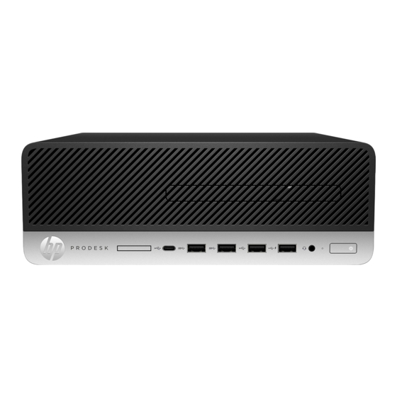
Page 10: Front Panel Components
Drive configuration may vary by model. Some models have a bezel blank covering the slim optical drive bay. Front panel components Slim optical drive (select products only) USB port with HP Sleep and Charge* Memory card reader (select products only) Audio-out (headphone)/Audio-in (microphone) -
Page 11: Rear Panel Components
DisplayPort monitor connectors (2) NOTE: Your model may have additional optional ports available from HP. When a graphics card is installed in one of the system board slots, the video connectors on the graphics card and/or the integrated graphics on the system board may be used. The specific graphics card installed and software configuration will determine the behavior. -
Page 12: Illustrated Parts Catalog
Illustrated parts catalog Serial number location Each computer has a unique serial number and a product ID number that are located on the exterior of the computer. Keep these numbers available for use when contacting support for assistance. Computer major components Description Access panel Front bezel... - Page 13 Description Intel Pentium Gold G5400 3.70-GHz processor (2400-MHz FSB, 4.0-MB SmartCache, dual core, 65-W) Intel Celeron G4900 3.10-GHz processor (2.0-MB SmartCache, dual core, 65-W) 180-W, 12-V, 82-percent high volume, 3 out connectors power supply (includes cables) Fan-sink, 65-W Fan duct shroud (includes cable) Speaker, 40×28.5-mm, 2-W, 4-ohm, 140-mm (includes cable) Hood sensor module Serial port modules:...
-
Page 14: Miscellaneous Parts
Description 500-GB, 7200-rpm, 3.5-in. 500-GB, 7200-rpm, 7.0-mm 500-GB, 5400-rpm, 7.0-mm, HYBRID 8-GB 500-GB, 5400-rpm 7.0-mm with Federal Information Processing Standard (FIPS) security and OPAL2 500-GB, 7200-rpm, 7.0-mm, with self-encryption (SED) and OPAL2 500-GB, 5400-rpm, Hybrid 8-GB NAND Solid-state drive: 1-TB, M2 2280, Non-Volatile Memory express (NVMe) solid-state drive with secure seal (SS) and triple-level cell (TLC) 512-GB, M2 2280, peripheral component interconnect express (PCIe), NVMe solid-state drive with SS and TLC 512-GB, M2 2280, PCIe, NVMe solid-state drive 512-GB M2 2280, PCIe3×4 solid-state drive with self-encryption (SED) and TLC... - Page 15 Power cord with 7A certification for use in Japan Adapters: HP DisplayPort–to–HDMI 2.0 adapter HP USB–to–Serial port adapter HP USB Type-C–to–DisplayPort adapter HP USB Type-C–to–USB 3.0 adapter HP USB Type-C–to–USB Type-A hub Cables: DisplayPort cable (1.83-m) DisplayPort–to–DVI cable DisplayPort–to–VGA cable...
- Page 16 AMD Radeon R7 430 2-GB LP 2DP PCIe×16 GFX AMD Radeon R7 430 2-GB LP DP VGA PCIe x16 Keyboards: HP antimicrobial slim business keyboard for use in the People’s Republic of China HP conferencing keyboard: For use in Asia/Pacific countries and regions...
- Page 17 For use in Turkey For use in the United Kingdom and Singapore For use in the United States HP PS/2 slim Windows 8 keyboard: For use in Belgium For use in Bosnia, Herzegovina, Croatia, Slovenia, and Yugoslavia For use in Brazil...
- Page 18 For use in Thailand For use in Turkey For use in the United Kingdom and Singapore For use in the United States HP USB slim business keyboard in grey finish: For use in France For use in Germany HP USB collaboration keyboard:...
- Page 19 For use in Taiwan For use in Turkey For use in the United Kingdom and Singapore For use in the United States HP USB essential keyboard: For use in India For use in Japan For use in Latin America For use in the People’s Republic of China...
- Page 20 For use in Turkey For use in the United Kingdom and Singapore For use in the United States HP USB slim Windows 8 keyboard: For use in Belgium For use in Bosnia, Herzegovina, Croatia, Slovenia, and Yugoslavia For use in Bulgaria...
- Page 21 For use in Turkey For use in the United Kingdom and Singapore For use in the United States HP USB slim Windows 8 keyboard with PCR: For use in Brazil For use in Latin America HP USB SmartCard slim keyboard with CCID:...
- Page 22 For use in Taiwan For use in Thailand For use in Turkey For use in the United Kingdom and Singapore For use in the United States HP wireless collaboration keyboard: For use in Belgium For use in Bulgaria Chapter 2 Illustrated parts catalog...
- Page 23 For use in Taiwan For use in Turkey For use in the United Kingdom and Singapore For use in the United States HP wireless premium keyboard: For use in Belgium For use in Bulgaria For use in Canada For use in Denmark...
- Page 24 For use in Turkey For use in the United Kingdom and Singapore For use in the United States HP wireless Windows 8 keyboard/mouse combination with dongle: For use in Belgium For use in Bosnia, Herzegovina, Croatia, Slovenia, and Yugoslavia For use in Brazil...
- Page 25 Description For use in Japan For use in Latin America For use in the Netherlands For use in Northwest Africa For use in Norway For use in the People’s Republic of China For use in Portugal For use in Russia For use in Saudi Arabia For use in South Korea For use in Spain...
- Page 26 Description For use in France For use in Greece For use in Hungary For use in Israel For use in Italy For use in Latin America For use in Northwest Africa For use in Norway For use in Portugal For use in Romania For use in Russia For use in Saudi Arabia For use in Spain...
- Page 27 Description For use in Latin America For use in the Netherlands For use in Northwest Africa For use in Norway For use in the People’s Republic of China For use in Portugal For use in Romania For use in Russia For use in Saudi Arabia For use in South Korea For use in Spain...
- Page 28 Unbranded USB/PS2 BFRAPVC washable Windows 8 keyboard: For use in Canada For use in Latin America For use in the United Kingdom For use in the United States Solenoid lock Mouse: HP PS/2 optical mouse Chapter 2 Illustrated parts catalog...
- Page 29 HP USB antimicrobial mouse HP USB hardened mouse HP USB laser mouse HP USB mouse in grey finish HP USB mouse in grey finish v.2 HP USB optical mouse HP USB premium mouse Moonraker Healthcare USB wired mouse USB PS/2 washable mouse USB 3.0 SD Card reader...
-
Page 30: Routine Care, Sata Drive Guidelines, And Disassembly Preparation
Routine care, SATA drive guidelines, and disassembly preparation This chapter provides general service information for the computer. Adherence to the procedures and precautions described in this chapter is essential for proper service. CAUTION: When the computer is plugged into an AC power source, voltage is always applied to the system board. -
Page 31: Preventing Electrostatic Damage To Equipment
Preventing electrostatic damage to equipment Many electronic components are sensitive to ESD. Circuitry design and structure determine the degree of sensitivity. The following packaging and grounding precautions are necessary to prevent damage to electric components and accessories. ● To avoid hand contact, transport products in static-safe containers such as tubes, bags, or boxes. ●... -
Page 32: Recommended Materials And Equipment
Recommended materials and equipment The following grounding equipment is recommended to prevent electrostatic damage: Antistatic tape ● Antistatic smocks, aprons, or sleeve protectors ● Conductive bins and other assembly or soldering aids ● ● Conductive foam ● Conductive tabletop workstations with ground cords of one-megohm +/- 10% resistance Static-dissipative table or floor mats with hard ties to ground ●... -
Page 33: Routine Care
Routine care General cleaning safety precautions Never use solvents or flammable solutions to clean the computer. Never immerse any parts in water or cleaning solutions; apply any liquids to a clean cloth and then use the cloth on the component. Always unplug the computer when cleaning with liquids or damp cloths. -
Page 34: Cleaning The Monitor
The screws used in the computer are not interchangeable. They may have standard or metric threads and may be of different lengths. If an incorrect screw is used during the reassembly process, it can damage the unit. HP strongly recommends that all screws removed during disassembly be kept with the part that was removed, then returned to their proper locations. -
Page 35: Cables And Connectors
HP. SMART ATA drives The Self Monitoring Analysis and Recording Technology (SMART) ATA drives for HP personal computers have built-in drive failure prediction that warns the user or network administrator of an impending failure (crash) of the hard drive. The SMART drive tracks fault prediction and failure indication parameters such as reallocated sector count, spin retry count, and calibration retry count. -
Page 36: Removal And Replacement Procedures
Removal and replacement procedures Adherence to the procedures and precautions described in this chapter is essential for proper service. After completing all necessary removal and replacement procedures, run the Diagnostics utility to verify that all components operate properly. NOTE: Not all features listed in this guide are available on all computers. Preparation for disassembly WARNING! Voltage is always present on the system board when the computer is plugged into an active... -
Page 37: Access Panel
Access panel Prepare the computer for disassembly (see Preparation for disassembly on page 28). Position the computer with the rear toward you. Slide the access panel release latch (1) to the right. Use the access panel release handle (2) to pull the access panel back. Remove the access panel (3). -
Page 38: Optical Drive
Optical drive Prepare the computer for disassembly (see Preparation for disassembly on page 28). Remove the access panel (see Access panel on page 29). Disconnect the optical drive SATA cable (1) from the back of the optical drive. Disconnect the optical drive power cable (2) from the back of the optical drive. Press the optical drive release latch (1). -
Page 39: Front Bezel
Front bezel Prepare the computer for disassembly (see Preparation for disassembly on page 28). Remove the access panel (see Access panel on page 29). Detach the four clips (1) on the top edge of the front bezel from the tabs on the computer chassis. Swing the top edge of the front cover (2) away from the computer chassis. -
Page 40: Hard Drives
Hard drives Follow these steps to remove a 2.5-inch hard drive: Prepare the computer for disassembly (see Preparation for disassembly on page 28). Remove the access panel (see Access panel on page 29). Disconnect the power cable (1) from the 2.5-inch hard drive. Disconnect the data cable (2) from the 2.5-inch hard drive. - Page 41 If it is necessary to remove the top hard drive from the 2.5-inch drive cage, follow the 1, 2, 3, 4 sequence (1) stamped in the cage to remove the four Torx-15 M3.0×7.5 screws (2) that secure the hard drive to the cage. Remove the hard drive from the 2.5-inch hard cage (3).
-
Page 42: Drive Cage
Drive cage Follow these steps to remove the drive cage: Prepare the computer for disassembly (see Preparation for disassembly on page 28). Remove the access panel (see Access panel on page 29). Disconnect all power cables and data cables from the hard drives installed in the drive cage (see Hard drives on page 32). -
Page 43: Memory Module
Memory module The computer has four memory module sockets. CAUTION: You must disconnect the power cord and wait approximately 30 seconds for the power to drain before adding or removing memory modules. Regardless of the power-on state, voltage is always supplied to the memory modules as long as the computer is plugged into an active AC outlet. -
Page 44: Speaker
Speaker Follow these steps to remove the speaker: Prepare the computer for disassembly (see Preparation for disassembly on page 28). Remove the access panel (see Access panel on page 29). Remove the front bezel (see Front bezel on page 31). Remove the drive cage (see Drive cage on page 34). -
Page 45: Power Supply
Power supply Follow these steps to remove the power supply: Prepare the computer for disassembly (see Preparation for disassembly on page 28). Remove the access panel (see Access panel on page 29). Remove the front bezel (see Front bezel on page 31). -
Page 46: Fan Shroud
Fan shroud Follow these steps to remove the fan shroud: Prepare the computer for disassembly (see Preparation for disassembly on page 28). Remove the access panel (see Access panel on page 29). Remove the front bezel (see Front bezel on page 31). -
Page 47: Fan-Sink
Fan-sink NOTE: The fan-sink spare park kit includes replacement thermal material. Follow these steps to remove the fan-sink: Prepare the computer for disassembly (see Preparation for disassembly on page 28). Remove the access panel (see Access panel on page 29), and then remove the following components: Front bezel (see Front bezel on page Drive cage (see... -
Page 48: Processor
Processor NOTE: The processor spare park kit includes replacement thermal material. Follow these steps to remove the fan-sink: Prepare the computer for disassembly (see Preparation for disassembly on page 28), and then remove the following components: Remove the access panel (see Access panel on page 29), and then remove the following components: Front bezel (see... - Page 49 Lift the processor (4) straight up and remove it. CAUTION: When installing the processor, the gold triangle (1) on the processor must be aligned with the triangle icon (2) embossed on the system board. Failure to follow this caution can result in damage to the pins on the processor and system board processor socket.
-
Page 50: Serial Connector Module
Serial connector module Follow these steps to remove the serial connector module: Prepare the computer for disassembly (see Preparation for disassembly on page 28). Remove the access panel (see Access panel on page 29), and then remove the following components: Front bezel (see Front bezel on page Drive cage (see... -
Page 51: System Board
System board NOTE: The system board spare park kit includes replacement thermal material. Follow these steps to remove the system board: Prepare the computer for disassembly (see Preparation for disassembly on page 28). Remove the access panel (see Access panel on page 29), and then remove the following components: Front bezel (see Front bezel on page... - Page 52 Remove the eight Torx-15 M3.0×9.0 screws that secure the system board to the computer chassis. Swing the top edge of the lower cage (1) away from the computer chassis. Remove the lower cage (2). Lift the front edge of the system board (1) until it rests at an angle. Chapter 4 Removal and replacement procedures...
- Page 53 Remove the system board (2) by sliding the front edge up and forward at an angle. Reverse this procedure to install the system board. System board...
-
Page 54: Connector Board
Connector board Follow these steps to remove the connector board: Prepare the computer for disassembly (see Preparation for disassembly on page 28). Remove the access panel (see Access panel on page 29), and then remove the following components: Front bezel (see Front bezel on page Drive cage (see Drive cage on page... -
Page 55: Computer Setup (F10) Utility
Computer Setup (F10) Utility Computer Setup (F10) Utilities Use Computer Setup (F10) Utility to do the following: Change settings from the defaults or restore the settings to default values. ● View the system configuration, including settings for processor, graphics, memory, audio, storage, ●... -
Page 56: Using Computer Setup (F10) Utilities
Using Computer Setup (F10) Utilities Computer Setup can be accessed only by turning the computer on or restarting the system. To access the Computer Setup Utilities menu, complete the following steps: Turn on or restart the computer. Repeatedly press when the monitor light turns green to access the utility. You can also press to a menu that allows you to access different options available at startup, including the Computer Setup utility. -
Page 57: Computer Setup-Main
● System Diagnostics If the hard drive has the HP Advanced Diagnostics installed, the application will launch. If HP Advanced Diagnostics is not installed, then a basic version built into the BIOS will provide the capability to perform the following functions: Memory Test ●... - Page 58 Update BIOS Using Local Media Lets you access files on either USB storage or the hard drive. The HP BIOS Update and Recovery application included in BIOS Softpaqs at www.hp.com will copy the BIOS file to the correct location on the hard drive or USB device.
-
Page 59: Computer Setup-Security
Computer Setup—Security NOTE: Support for specific Computer Setup options may vary depending on the hardware configuration. Table 5-2 Computer Setup—Security Option Description Set up BIOS Administrator Lets you set and enable a BIOS administrator password, which includes the following privileges: Password ●... - Page 60 Table 5-2 Computer Setup—Security (continued) Option Description Data Recovery Policy ● Select ‘Automatic’ or ‘Manual’ to set data recovery policy. ‘Manual’ lets you select whether or not to execute recovery of a corrupted region if it is detected. Set Up BIOS Power-On Lets you set and enable a BIOS power-on password.
-
Page 61: Computer Setup-Advanced
Table 5-2 Computer Setup—Security (continued) Option Description Default is ‘Unlock’. Cover Removal Sensor (Disabled/Notify user/Administrator password) Lets you disable the cover sensor or configure what action is taken if the computer cover was removed. Default is ‘Disabled’. NOTE: Notify user alerts the user with a POST error on the first boot after the sensor detects removal of the cover. - Page 62 Table 5-3 Computer Setup—Advanced (for advanced users) (continued) Option Heading UEFI boot sources always have precedence over legacy boot sources. Legacy Boot Order ● Specify the order in which legacy boot sources (such as a network interface card, internal hard drive, USB optical drive, or internal optical drive) are checked for a bootable operating system image.
- Page 63 Table 5-3 Computer Setup—Advanced (for advanced users) (continued) Option Heading Controls the virtualization features of the processor. Changing this setting requires turning the computer off and then back on. Default is disabled. Virtualization Technology for Directed I/O (VTd) (Intel only) Controls virtualization DMA remapping features of the chipset.
- Page 64 Table 5-3 Computer Setup—Advanced (for advanced users) (continued) Option Heading Clear to disable the display panel touch feature. Default is enabled. Port Options Allows you to hide the following ports from the operating system: Serial port A ● ● Serial port B SATA0 ●...
- Page 65 Table 5-3 Computer Setup—Advanced (for advanced users) (continued) Option Heading Enables or disables SATA bus and/or device power management. Default is enabled. PCI Express Power Management (enable/disable) Enabling this option permits the PCI Express links to use Active Power State Management (ASPM) to enter lower power states while not in use.
-
Page 66: Recovering The Configuration Settings
Recovering the Configuration Settings This method of recovery requires that you first perform the Save to Removable Media command with the Computer Setup (F10) Utility before Restore is needed. (See Computer Setup–Main on page 49 the Computer Setup—File table.) The Save to Removable Media option creates a file named HPSETUP.TXT on an inserted USB flash media device. -
Page 67: Troubleshooting Without Diagnostics
To assist you in resolving problems online, HP Instant Support Professional Edition provides you with self-solve diagnostics. If you need to contact HP support, use HP Instant Support Professional Edition's online chat feature. Access HP Instant Support Professional Edition at: http://www.hp.com/go/ispe. -
Page 68: Helpful Hints
If it becomes necessary to call for technical assistance, be prepared to do the following to ensure that your service call is handled properly: Be in front of your computer when you call. ● ● Write down the computer serial number, product ID number, and monitor serial number before calling. ●... -
Page 69: Solving General Problems
If you have installed an operating system other than the factory-installed operating system, check to be ● sure that it is supported on the system. If the system has multiple video sources (embedded, PCI, or PCI-Express adapters) installed (embedded ● video on some models only) and a single monitor, the monitor must be plugged into the monitor connector on the source selected as the primary VGA adapter. - Page 70 In case of forgotten password, power loss, or computer malfunction, you must manually disable the Smart Cover lock . A key to unlock the Smart Cover Lock is not available from HP. Keys are typically available from a hardware store.
- Page 71 Poor performance. Cause Solution Hard drive fragmented. Defragment hard drive. Program previously accessed did not release reserved memory Restart the computer. back to the system. Virus resident on the hard drive. Run virus protection program. Too many applications running. Close unnecessary applications to free up memory. Add more memory.
-
Page 72: Solving Power Problems
System does not power on and the LEDs on the front of the computer are not flashing. Cause Solution Remove the expansion cards one at a time until the 5V_aux light on the system board turns on. Replace the system board. Press and hold the power button for less than 4 seconds. -
Page 73: Solving Hard Drive Problems
Power LED flashes red four times, once every second, followed by a two second pause, and the computer beeps four times. (Beeps stop after fifth iteration but LEDs continue flashing.) Computer powered off automatically and the Power LED flashes red three times and then white four times. - Page 74 Drive not found (identified). Cause Solution Computer Setup. If it is listed, the probable cause is a driver problem. If it is not listed, the probable cause is a hardware problem. If this is a newly installed drive, run the Computer Setup utility and try adding a POST delay under Advanced >...
-
Page 75: Solving Media Card Reader Problems
Computer seems to be locked up. Cause Solution Program in use has stopped responding to commands. Use the task manager to close programs that do not respond. Attempt the normal Windows “Shut Down” procedure. If this fails, press the power button for four or more seconds to turn off the power. -
Page 76: Solving Display Problems
Do not know how to remove a media card correctly. Cause Solution The computer’s software is used to safely eject the card. Type file in the taskbar search box, and then select File Explorer from the list of applications. In the left column, expand This PC, right-click on the corresponding drive icon, and then select Eject. - Page 77 Reseat DIMMs. Power on the system. Replace DIMMs one at a time to isolate the faulty module. Replace third-party memory with HP memory. Replace the system board. Blank screen and the power LED flashes Red six times, once every second, followed by a two second pause, and the computer beeps six times.
- Page 78 Blank screen and the power LED flashes Red seven times, once every second, followed by a two second pause, and the computer beeps seven times. (Beeps stop after fifth iteration but LEDs continue flashing.) Cause Solution System board failure (ROM detected failure prior to video). Replace the system board.
- Page 79 Image is not centered. Cause Solution Position may need adjustment. Press the monitor's Menu button to access the OSD menu. Select ImageControl/ Horizontal Position or Vertical Position to adjust the horizontal or vertical position of the image. “No Connection, Check Signal Cable” displays on screen. Cause Solution Monitor video cable is disconnected.
-
Page 80: Solving Audio Problems
(flat panel monitors using an analog VGA input connection only). Cause Solution the appropriate monitor, and download either SP32347 or SP32202: http://www.hp.com/support Graphics card is not seated properly or is bad (some models). Reseat the graphics card. Replace the graphics card. Certain typed symbols do not appear correct. - Page 81 Sound does not come out of the speaker or headphones. Cause Solution CAUTION: When attempting to resume from Sleep state, do not hold down the power button for more than four seconds. Otherwise, the computer will shut down and you will lose any unsaved data.
-
Page 82: Solving Printer Problems
There is no sound or very weak sound is detected by the headset microphone. Cause Solution connector. To solve the issue, use a CTIA style headset or a commercially available adapter that will convert from OMTP to CTIA signaling. There is no sound or sound volume is too low. Cause Solution The application is set to use a different audio device than speakers. -
Page 83: Solving Keyboard And Mouse Problems
Printer prints garbled information. Cause Solution The correct printer driver for the application is not installed. Install the correct printer driver for the application. The cables may not be connected properly. Reconnect all cables. Printer memory may be overloaded. Reset the printer by turning it off for one minute, then turn it back Printer will not print. - Page 84 Mouse does not respond to movement or is too slow. Cause Solution Mouse connector is not properly plugged into the back of Shut down the computer using the keyboard. the computer. Press the Ctrl keys at the same time (or press Windows logo key) to display the Start menu.
-
Page 85: Solving Hardware Installation Problems
Solving hardware installation problems You may need to reconfigure the computer when you add or remove hardware, such as an additional drive or expansion card. If you install a plug and play device, Windows automatically recognizes the device and configures the computer. If you install a non-plug and play device, you must reconfigure the computer after completing installation of the new hardware. -
Page 86: Solving Network Problems
DIMM1 or XMM1 must always be installed. DIMM1 must be installed before DIMM2, and DIMM3 must be installed before DIMM4 Replace third-party memory with HP memory. Replace the system board. Solving network problems Some common causes and solutions for network problems are listed in the following table. These guidelines do not discuss the process of debugging the network cabling. - Page 87 Table 6-2 Solving network problems (continued) Network status link light never flashes. NOTE: The network status light is supposed to flash when there is network activity. Cause Solution Enable the network controller in the operating system using Device Manager. To access Device Manager, type device manager in the taskbar search box, and then select Device Manager from the list of applications.
- Page 88 Network controller stops working without apparent cause. Cause Solution The files containing the network drivers are corrupted. Reinstall the network drivers using the Windows recovery tools. If necessary, download the softpaq from the web (from a different computer). The cable is not securely connected. Ensure that the cable is securely attached to the network connector and that the other end of the cable is securely attached to the correct device.
-
Page 89: Solving Memory Problems
Management Engine (ME) settings). To avoid damage to the DIMMs or the system board, you must unplug the computer power cord before attempting to reseat, install, or remove a memory module. For those systems that support ECC memory, HP does not support mixing ECC and non-ECC memory. Otherwise, the computer will not boot the operating system. -
Page 90: Solving Usb Flash Drive Problems
Memory is installed incorrectly or is bad. Reseat DIMMs. Power on the system. Replace DIMMs one at a time to isolate the faulty module. Replace third-party memory with HP memory. Replace the system board. Solving USB flash drive problems If you encounter USB flash drive problems, common causes and solutions are listed in the following table. -
Page 91: Solving Front Panel Component Problems
Solving front panel component problems If you encounter problems with devices connected to the front panel, refer to the common causes and solutions listed in the following table. A USB device, headphone, or microphone is not recognized by the computer. Cause Solution Device is not properly connected. -
Page 92: Solving Software Problems
● sure it is supported on the system. If you encounter software problems, see the applicable solutions listed in the following table. Computer will not continue and the HP logo does not display. Cause Solution ROM issue - POST error has occurred. -
Page 93: Post Error Messages And Diagnostic Front Panel Leds And Audible Codes
POST error messages and diagnostic front panel LEDs and audible codes This appendix lists the error codes, error messages, and the various indicator light and audible sequences that you may encounter during Power-On Self-Test (POST) or computer restart, the probable source of the problem, and steps you can take to resolve the error condition. - Page 94 Control panel message Description Recommended action RTC (real-time clock) battery may need to the problem persists, replace the RTC battery. be replaced. See the Removal and Replacement section for instructions on installing a new battery. 008–Microcode Patch Error Processor is not supported by the BIOS. Upgrade BIOS to proper version.
- Page 95 Run the Drive Protection erroneous error message.) System test under using F2 Diagnostics when booting the computer. Apply hard drive firmware patch if applicable. (Available at http://www.hp.com/support.) Back up contents and replace hard drive. POST numeric codes and text messages...
- Page 96 System test under using F2 Diagnostics when booting the computer. Apply hard drive firmware patch if applicable. (Available at http://www.hp.com/support.) Back up contents and replace hard drive. 309 – 30C: Hard Disk 3–6: SMART Hard Drive Hard drive is about to fail. (Some hard drives...
- Page 97 Control panel message Description Recommended action 419-Out of Memory Space for Option ROMs Recently added PCI expansion card contains an ▲ If a PCI expansion card was recently added, option ROM too large to download during POST. remove it to see if the problem remains. 41A-Front USB1/USB2 Not Connected Front USB cable has been detached or unseated Reconnect or replace front USB cable.
-
Page 98: Interpreting System Validation Diagnostic Front Panel Leds And Audible Codes
Control panel message Description Recommended action Replace fan. 90D-System Temperature Thermal shutdown occurred. The system BIOS Make sure system has proper airflow. has detected your machine was previously shut down to avoid overheating. Overheating may occur if the cooling vents are blocked or the operating temperature exceeds the system specifications. - Page 99 Patterns of blink/beep codes are determined by using the following parameters: 1 second pause occurs after the last major blink. ● 2 second pause occurs after the last minor blink. ● Beep error code sequences occur for the first 5 iterations of the pattern and then stop. ●...
-
Page 100: Password Security And Resetting Cmos
If you lose or forget the password when in stringent security mode, the system can only be reset by System Management Command. This is a way for HP Service and Support to provide a secure method to access the BIOS and command a password reset for a specifically identified unit under the direction of the owner. -
Page 101: Resetting Cmos And/Or The Password Jumper
If you lose or forget the password when in stringent security mode, the system can only be reset by System Management Command. This is a way for HP Service and Support to provide a secure method to access the BIOS and command a password reset for a specifically identified unit under the direction of the owner. - Page 102 Shut down the operating system properly, then turn off the computer and any external devices, and disconnect the power cord from the power outlet. With the power cord disconnected, press the power button again to drain the system of any residual power. WARNING! To reduce the risk of personal injury from electrical shock and/or hot surfaces, be sure to disconnect the power cord from the wall outlet, and allow the internal system components to cool before...
-
Page 103: Changing A Setup Or Power-On Password
Changing a Setup or Power-on password To change the power-on or setup password, complete the following steps: Turn on or restart the computer. To change the Setup password, go to step 2. To change the Power-on password, go to step 3. To change the Setup password, as soon as the computer turns on: - Press the Esc key while “Press the ESC key for Startup Menu”... -
Page 104: Using Hp Pc Hardware Diagnostics (Uefi)
Using HP PC Hardware Diagnostics (UEFI) HP PC Hardware Diagnostics is a Unified Extensible Firmware Interface (UEFI) that allows you to run diagnostic tests to determine whether the computer hardware is functioning properly. The tool runs outside the operating system so that it can isolate hardware failures from issues that are caused by the operating system or other software components. -
Page 105: Downloading Hp Pc Hardware Diagnostics (Uefi) To A Usb Device
NOTE: The HP PC Hardware Diagnostics (UEFI) download instructions are provided in English only, and you must use a Windows computer to download and create the HP UEFI support environment because only .exe files are offered. There are two options to download HP PC Hardward Diagnostics to USB device. -
Page 106: 10 System Backup And Recovery
Use HP Recovery Manager to create HP Recovery media after you successfully set up the computer. This ● step creates a backup of the HP Recovery partition on the computer. The backup can be used to reinstall the original operating system in cases where the hard drive is corrupted or has been replaced. For... -
Page 107: Creating Hp Recovery Media (Select Products Only)
HP Recovery media can also be used to customize the system or restore the factory image if you replace the hard drive. -
Page 108: Using Windows Tools
On select products, if you want to recover the computer's original factory partition and content, or if you ● have replaced the hard drive, you can use the Factory Reset option of HP Recovery media. For more information, see Recovering using HP Recovery Manager on page 101. -
Page 109: Recovering Using Hp Recovery Manager
Creating HP Recovery media (select products only) on page ● If your computer does not allow the creation of HP Recovery media or if the HP Recovery media does not work, you can obtain recovery media for your system from support. See the Worldwide Telephone Numbers booklet included with the computer. -
Page 110: Using Hp Recovery Media To Recover
Using HP Recovery media to recover You can use HP Recovery media to recover the original system. This method can be used if your system does not have an HP Recovery partition or if the hard drive is not working properly. -
Page 111: Appendix A Battery Replacement
The lifetime of the lithium battery can be extended by plugging the computer into a live AC wall socket. The lithium battery is only used when the computer is NOT connected to AC power. HP encourages customers to recycle used electronic hardware, HP original print cartridges, and rechargeable batteries. For more information about recycling programs, go to http://www.hp.com/recycle. - Page 112 Slide the replacement battery into position, positive side up. The battery holder automatically secures the battery in the proper position. Type 2 To release the battery from its holder, squeeze the metal clamp that extends above one edge of the battery. When the battery pops up, lift it out (1). To insert the new battery, slide one edge of the replacement battery under the holder’s lip with the positive side up.
- Page 113 Insert the new battery and position the clip back into place. NOTE: After the battery has been replaced, use the following steps to complete this procedure. Replace the access panel. Plug in the computer and turn on power to the computer. Reset the date and time, your passwords, and any special system setups using Computer Setup.
-
Page 114: Appendix B Statement Of Memory Volatility
Statement of memory volatility The purpose of this chapter is to provide general information regarding nonvolatile memory in HP Business PCs. This chapter also provides general instructions for restoring nonvolatile memory that can contain personal data after the system has been powered off and the hard drive has been removed. - Page 115 Select the Main menu, and then select Reset BIOS Security to factory default. Click Yes at the warning message. The computer will reboot. During the reboot, press esc. NOTE: If the system has a BIOS administrator password, enter the password at the prompt. Select the Main menu, select Apply Factory Defaults and Exit, select Yes to save changes and exit, and then select Shutdown.
-
Page 116: Nonvolatile Memory Usage
A utility is required for Computer Setup (BIOS) or a writing data to this custom utility. memory and is available on the HP website; go to http://www.hp.com/ support, and select your country. Select Drivers & Downloads, and then 108 Appendix B Statement of memory volatility... - Page 117 Does this Does this memory memory store retain data What is the Nonvolatile customer when power purpose of this How is data input into this How is this memory write- memory type Amount (Size) data? is removed? memory? memory? protected? follow the on-screen instructions.
-
Page 118: Questions And Answers
HP has provided options in Computer Setup (BIOS) to allow you to run in legacy BIOS, if required by the operating system. Examples of this requirement would be if you upgrade or downgrade the OS. -
Page 119: Using Hp Sure Start
BIOS to its previously safe state, without user intervention. Those select computer models ship with HP Sure Start configured and enabled. HP Sure Start is configured and already enabled so that most users can use the HP Sure Start default configuration. The default configuration can be customized by advanced users. -
Page 120: Appendix C Power Cord Set Requirements
Power cord set requirements The power supplies on some computers have external power switches. The voltage select switch feature on the computer permits it to operate from any line voltage between 100-120 or 220-240 volts AC. Power supplies on those computers that do not have external power switches are equipped with internal switches that sense the incoming voltage and automatically switch to the proper voltage. -
Page 121: Country-Specific Requirements
Country-specific requirements Additional requirements specific to a country are shown in parentheses and explained below. Country Accrediting Agency Country Accrediting Agency Australia (1) EANSW Italy (1) Austria (1) Japan (3) METI Belgium (1) CEBC Norway (1) NEMKO Canada (2) Sweden (1) SEMKO Denmark (1) DEMKO... -
Page 122: Appendix D Specifications
Specifications Unit Value Chassis (in the desktop position) 3.7 in 95 mm Height 10.6 in 270 mm Width 11.8 in 300 mm Depth Approximate Weight 9.8 lb 4.43 kg Weight Supported (maximum distributed load in desktop position) 77 lb 35 kg Temperature Range 50°... - Page 123 2 audible codes 90 power cord 3 helpful hints 60 audio problems 72 country power cord set HP PC Hardware Diagnostics (UEFI) audio-in jack 2, 3 requirements 113 downloading 97 audio-out jack 2, 3 Customer Support 59 HP Sure Start 111...
- Page 124 46 power-on 92 drive cage 34 setup 92 USB port 2, 3 fan shroud 38 passwords 95 USB port with HP Sleep and Charge fan-sink 39 ports front bezel 31 optional 3 USB SuperSpeed ports 3 hard drives 32...
Need help?
Do you have a question about the ProDesk 600 G4 SFF and is the answer not in the manual?
Questions and answers
I just purchased a refurbished HP deskpro g4 pc through amazon .I **** not able to open the card reader slot . it has a slot for a card reader and is supposed to have one on this model
To open the card reader slot on an HP ProDesk 600 G4 SFF, ensure the media card is properly inserted with the gold contacts on the correct side. If you need to remove a card, use the computer’s software to safely eject it. Type "file" in the taskbar search box, select File Explorer, expand "This PC" in the left column, right-click the corresponding drive icon, and select "Eject." Then, pull the card out of the slot. Never remove the card when the green LED is flashing.
This answer is automatically generated