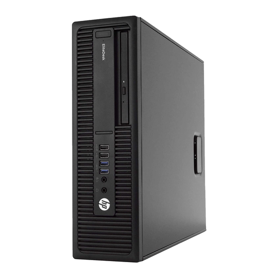
HP EliteDesk 800 G2 Desktop Mini Maintenance And Service Manual
Hide thumbs
Also See for EliteDesk 800 G2 Desktop Mini:
- Installation manual ,
- Maintenance and service manual (154 pages) ,
- Hardware reference manual (52 pages)

Related Manuals for HP EliteDesk 800 G2 Desktop Mini


Summary of Contents for HP EliteDesk 800 G2 Desktop Mini
- Page 1 Maintenance and Service Guide HP EliteDesk 800 G2 Desktop Mini HP EliteDesk 705 G2 Desktop Mini HP ProDesk 600 G2 Desktop Mini HP ProDesk 400 G2 Desktop Mini HP MP9 G2 Retail System...
- Page 2 HP Inc. under license. bound by the terms of the HP End User License Not all features are available in all editions of Intel, Celeron, and Pentium are trademarks of Agreement (EULA).
- Page 3 Safety warning notice WARNING! To reduce the possibility of heat-related injuries or of overheating the device, do not place the device directly on your lap or obstruct the device air vents. Use the device only on a hard, flat surface. Do not allow another hard surface, such as an adjoining optional printer, or a soft surface, such as pillows or rugs or clothing, to block airflow.
- Page 4 Safety warning notice...
-
Page 5: Table Of Contents
Front panel components (EliteDesk 800, ProDesk 600, and HP MP9) ..............1 Front panel components (EliteDesk 705 and ProDesk 400) ................. 2 Rear panel components (EliteDesk 800, EliteDesk 705, ProDesk 600, and HP MP9) .......... 3 Rear panel components (ProDesk 400) ......................... 4 Serial number location ............................ - Page 6 Speaker ................................47 Expansion connector board ..........................48 System board ............................... 49 System board callouts, EliteDesk 800, ProDesk 600, and HP MP9 Retail System ......51 System board callouts, EliteDesk 705 ....................52 System board callouts, ProDesk 400 ....................53 Internal WLAN antenna cable removal/installation ....................
- Page 7 Clearing and resetting the BIOS ........................111 9 Using HP PC Hardware Diagnostics (UEFI) ..................... 113 Downloading HP PC Hardware Diagnostics (UEFI) to a USB device ..............113 10 System backup and recovery ........................115 Backing up, restoring, and recovering in Windows 10 ..................115 Creating recovery media and backups ....................
- Page 8 Creating recovery media ......................... 122 Creating recovery media using HP Recovery Manager (select models only) ....122 Creating recovery discs with HP Recovery Disc Creator (select models only) ..... 123 Creating recovery discs ................124 Backing up your information ..................124 System Restore ..........................
-
Page 9: Product Features
Several well-known vulnerabilities exist when a computer is in the Sleep state. To prevent an unauthorized user from accessing data on your computer, even encrypted data, HP recommends that you always initiate Hibernation instead of Sleep anytime the computer will be out of your physical possession. -
Page 10: Front Panel Components (Elitedesk 705 And Prodesk 400)
Front panel components (EliteDesk 705 and ProDesk 400) NOTE: Your computer model may look slightly different from the illustration in this section. Headphone Connector USB 3.0 Port Microphone Connector HDD Activity LED USB 3.0 Port-Charging Dual-State Power Button NOTE: This USB 3.0 connector does not offer port charging on 400 models. -
Page 11: Rear Panel Components (Elitedesk 800, Elitedesk 705, Prodesk 600, And Hp Mp9)
On 705 models this is a USB 2.0 port that supports only the S4 power state. External Antenna Connector (optional) RJ-45 Network Connector Wireless antenna Power Connector DisplayPort Monitor Connector Rear panel components (EliteDesk 800, EliteDesk 705, ProDesk 600, and HP MP9) -
Page 12: Rear Panel Components (Prodesk 400)
Rear panel components (ProDesk 400) NOTE: Your computer model may look slightly different from the illustration in this section. External Antenna Connector (optional) VGA Monitor Connector Thumbscrew Serial Port Padlock Loop USB 3.0 Ports (2) (blue) with support for wake from S4/S5 power states Cable Lock Slot USB 2.0 Connectors (2) (black) -
Page 13: Serial Number Location
Serial number location Each computer has a unique serial number and a product ID number that are located on the exterior of the computer. Keep these numbers available for use when contacting customer service for assistance. Serial number location... -
Page 14: Illustrated Parts Catalog
Desktop Mini (DM) chassis spare parts NOTE: HP continually improves and changes product parts. For complete and current information on supported parts for your computer, go to http://partsurfer.hp.com, select your country or region, and then follow the on-screen instructions. Computer major components... - Page 15 Item Description Memory modules (DDR3, PC3-12800, 1600-MHz)(for use in EliteDesk 705 models) 8-GB 4-GB Memory modules (DDR4, PC4-17000, 2133-MHz)(for use in EliteDesk 800, ProDesk 600, ProDesk 400, and MP9 models) 16-GB 8-GB 4-GB Intel Processors (800, 600, 400, MP9 models; include replacement thermal material) Intel Core i7-6700 Intel Core i7-6700T Intel Core i5-6600...
-
Page 16: Cables
Cables Item Description SATA cable/connector NOTE: Included with computer. Tab color may vary. Adapter, DisplayPort to HDMI 1.4 Adapter, DisplayPort to VGA Adapter, DisplayPort to DVI Adapter, USB-C to USB 3.0 (800, 600, MP9 models) DisplayPort cable USB to serial adapter Chapter 2 Illustrated parts catalog... -
Page 17: Misc Parts
Secondary hard drive fan (for use in EliteDesk 800 and MP9, 65W models) Speaker Power switch/light cover Option board, HDMI Option board, serial port Option board, DisplayPort (not illstrated) Thermal sensor Hood sensor assembly Stand Port cover HP Ultraslim Keyed Cable Lock Desktop Mini (DM) chassis spare parts... - Page 18 Intel Dual Band Wireless-AC 7265 NV Intel Dual Band Wireless-AC 8260 + Bluetooth 4.0 Intel Dual Band Wireless-AC 3165 + Bluetooth 4.0 HP WLAN 802.11 a/b/g/n + Bluetooth 4.0 Antenna, dual band dipole, 802.11a/b/g/n + Velcro External antenna kit Expansion Module Kit Hard drive –...
-
Page 19: Drives
Drives Description Hard drives 2 TB, 5400 rpm, hard drive, 2.5-inch 1 TB, 7200 rpm, hard drive, 2.5-inch 1 TB, 7200 rpm, hard drive, 2.5-inch, SSHD (hybrid SSD) 500 GB, 7200 rpm hard drive, 2.5-inch 500 GB, 2.5-inch, SSHD (hybrid SSD) 500 GB, 7200 rpm hard drive, 2.5-inch, OPAL 2, SED 500 GB, 5400 rpm hard drive, 2.5-inch, FIPS Solid-state drives... -
Page 20: Routine Care, Sata Drive Guidelines, And Disassembly Preparation
Routine care, SATA drive guidelines, and disassembly preparation This chapter provides general service information for the computer. Adherence to the procedures and precautions described in this chapter is essential for proper service. CAUTION: When the computer is plugged into an AC power source, voltage is always applied to the system board. -
Page 21: Preventing Electrostatic Damage To Equipment
Preventing electrostatic damage to equipment Many electronic components are sensitive to ESD. Circuitry design and structure determine the degree of sensitivity. The following packaging and grounding precautions are necessary to prevent damage to electric components and accessories. ● To avoid hand contact, transport products in static-safe containers such as tubes, bags, or boxes. ●... -
Page 22: Recommended Materials And Equipment
Recommended materials and equipment Materials and equipment that are recommended for use in preventing static electricity include: ● Antistatic tape ● Antistatic smocks, aprons, or sleeve protectors Conductive bins and other assembly or soldering aids ● ● Conductive foam ● Conductive tabletop workstations with ground cord of one-megohm +/- 10% resistance ●... -
Page 23: Routine Care
● Never cover the ventilation slots on the monitor with any type of material. Install or enable power management functions of the operating system or other software, including ● sleep states. Routine care General cleaning safety precautions Never use solvents or flammable solutions to clean the computer. Never immerse any parts in water or cleaning solutions;... -
Page 24: Cleaning The Monitor
The screws used in the computer are not interchangeable. They may have standard or metric threads and may be of different lengths. If an incorrect screw is used during the reassembly process, it can damage the unit. HP strongly recommends that all screws removed during disassembly be kept with the part that was removed, then returned to their proper locations. -
Page 25: Cables And Connectors
Batteries, battery packs, and accumulators should not be disposed of together with the general household waste. In order to forward them to recycling or proper disposal, please use the public collection system or return them to HP, their authorized partners, or their agents. SATA hard drives... -
Page 26: Sata Hard Drive Cables
6.0 Gb/s SATA hard drive cables SATA data cable Always use an HP approved SATA 6.0 Gb/s cable as it is fully backwards compatible with the SATA 1.5 Gb/s drives. Current HP desktop products ship with SATA 6.0 Gb/s hard drives. -
Page 27: Cable Management
Cable management Always follow good cable management practices when working inside the computer. Keep cables away from major heat sources like the heat sink. ● ● Do not jam cables on top of expansion cards or memory modules. Printed circuit cards like these are not designed to take excessive pressure on them. -
Page 28: Removal And Replacement Procedures - Desktop Mini (Dm) Chassis
Not all features listed in this guide are available on all computers. NOTE: HP continually improves and changes product parts. For complete and current information on supported parts for your computer, go to http://partsurfer.hp.com, select your country or region, and then follow the on-screen instructions. Preparation for disassembly Routine care, SATA drive guidelines, and disassembly preparation on page 12 for initial safety procedures. -
Page 29: Top Cover
Top cover Prepare the computer for disassembly (Preparation for disassembly on page 20). Loosen the thumbscrew on the rear of the computer (1). Slide the panel forward and lift if off the computer (2). NOTE: Your computer model may look slightly different from the illustration in this section. To install the top cover, reverse the removal procedure. -
Page 30: Front Bezel
Front bezel The front bezel is secured to the top cover by tabs. Prepare the computer for disassembly (Preparation for disassembly on page 20). Remove the top cover (Top cover on page 21). Position the top cover upside-down so you can access the inside of the bezel. Pull down to loose the bottom, interior on the bezel (1). -
Page 31: Hard Drive
Hard drive Description Hard drives 2 TB, 5400 rpm, hard drive, 2.5-inch 1 TB, 7200 rpm, hard drive, 2.5-inch 1 TB, 7200 rpm, hard drive, 2.5-inch, SSHD (hybrid SSD) 500 GB, 7200 rpm hard drive, 2.5-inch 500 GB, 2.5-inch, SSHD (hybrid SSD) 500 GB, 7200 rpm hard drive, 2.5-inch, OPAL 2, SED 500 GB, 5400 rpm hard drive, 2.5-inch, FIPS Solid-state drives... - Page 32 Pull the release lever next to the rear of the HDD away from the HDD (2). While pulling the release lever out, slide the drive back until it stops, then lift the HDD up and out of the cage (3). To install a HDD, you must transfer the silver and blue isolation mounting guide screws from the old HDD to the new HDD.
- Page 33 Connect the HDD power and data cable (2) to the HDD. Reverse this procedure to replace the hard drive. Hard drive...
-
Page 34: Secondary Fan (Elitedesk 800 And Mp9 Models Only)
Secondary fan (EliteDesk 800 and MP9 models only) HP EliteDesk 800 G2 and HP MP9 G2 Retail System models include a secondary fan installed under the hard drive. Prepare the computer for disassembly (Preparation for disassembly on page 20). Remove the top cover (Top cover on page 21). -
Page 35: Drive Cage
Drive cage The drive cage is located next to the heat sink. The drive cage is secured with three Phillips screws. Prepare the computer for disassembly (Preparation for disassembly on page 20). Remove the top cover (Top cover on page 21). -
Page 36: Pcie Solid State Drive (Ssd)
M.2 PCIe solid state drive (SSD) Description 256 GB solid-state drive (SSD), PCIe, 2280, NVMe 256 GB solid-state drive (SSD), PCIe, 2280SS 128 GB solid-state drive (SSD), PCIe, 2280, NVMe 128 GB solid-state drive (SSD), PCIe, 2280SS Prepare the computer for disassembly (Preparation for disassembly on page 20). - Page 37 Press the SSD down to the system board and use the included screw to secure the SSD. M.2 PCIe solid state drive (SSD)
-
Page 38: Wlan Module
Intel Dual Band Wireless-AC 8260 + Bluetooth 4.0 Intel Dual Band Wireless-AC 3165 + Bluetooth 4.0 HP WLAN 802.11 a/b/g/n + Bluetooth 4.0 The WLAN module is secured with one Phillips screw and has two connected antennas. It is located under the hard drive. - Page 39 Attach the internal antenna to the antenna connectors (3) on the WLAN module. To install the WLAN module, reverse the removal procedure. NOTE: WLAN modules are designed with a notch to prevent incorrect insertion. WLAN module...
-
Page 40: External Antenna
External antenna The antennas route from the WLAN module to the cable connectors on the rear of the computer. To install the antennas: Prepare the computer for disassembly (Preparation for disassembly on page 20). Remove the top cover (Top cover on page 21). - Page 41 Insert a Phillips screwdriver in each knock-out feature and rotate to remove the blank. Feed the external antenna cable through each hole and screw the antenna into position. Connect the external antenna cables to the WLAN module. Reverse the removal procedure to install the WLAN antennas and transceivers. External antenna...
-
Page 42: Rtc Battery
The lithium battery is only used when the computer is NOT connected to AC power. HP encourages customers to recycle used electronic hardware, HP original print cartridges, and rechargeable batteries. For more information about recycling programs, go to http://www.hp.com/recycle. - Page 43 Locate the battery and battery holder on the system board. NOTE: You may need to use a small tool, such as tweezers or needle-nose pliers, to remove and replace the battery. Lift the battery out of the holder. Slide the replacement battery into position, positive side up. The battery holder automatically secures the battery in the proper position.
-
Page 44: Thermal Sensor
Thermal sensor A thermal sensor installs at the front of the computer near the speaker. Adhesive secures the sensor to the chassis that houses the speaker. To remove the thermal sensor: Prepare the computer for disassembly (Preparation for disassembly on page 20). -
Page 45: Fan
The fan sits between the fan sink and the front of the computer. Prepare the computer for disassembly (Preparation for disassembly on page 20). Remove the top cover (Top cover on page 21). Lift the tab on the outer edge of the fan and rotate the fan upward. Disconnect the fan plug from the system board, and then lift the fan out of the chassis. -
Page 46: Power Switch/Light Cover
Power switch/light cover The power switch/light cover is located at the front, right of the computer, under the top cover. Prepare the computer for disassembly (Preparation for disassembly on page 20). Remove the top cover (Top cover on page 21). Remove the fan (Fan on page 37). -
Page 47: Memory
Description Memory modules (PC3-12800, 1600-MHz)(for use in EliteDesk 705 models) 8-GB 4-GB Memory modules (PC4-17000, 2133-MHz)(for use in EliteDesk 800, ProDesk 600, ProDesk 400, and HP MP9 G2 Retail System models) 16-GB 8-GB 4-GB The computer comes with small outline, dual inline memory modules (SODIMMs). -
Page 48: Populating Sodimm Sockets
HP offers upgrade memory for this computer and advises that the consumer purchase it to avoid compatibility issues with unsupported third-party memory. Populating SODIMM sockets There are two SODIMM sockets on the system board, with one socket per channel. The sockets are labeled DIMM1 and DIMM3. -
Page 49: Replacing Sodimms
Replacing SODIMMs CAUTION: You must disconnect the power cord and wait approximately 30 seconds for the power to drain before adding or removing memory modules. Regardless of the power-on state, voltage is always supplied to the memory modules as long as the computer is plugged into an active AC outlet. Adding or removing memory modules while voltage is present may cause irreparable damage to the memory modules or system board. - Page 50 To remove a SODIMM, press outward on the two latches on each side of the SODIMM (1) then pull the SODIMM out of the socket (2). Slide the new SODIMM into the socket at approximately a 30° angle (1) then press the SODIMM down (2) so that the latches lock it in place.
-
Page 51: Heat Sink
Heat sink The heat sink is secured with four captive Torx screws. Prepare the computer for disassembly (Preparation for disassembly on page 20). Remove the top cover (Top cover on page 21). Remove the fan (Fan on page 37). In the order indicated on the heat sink, loosen the three captive Torx screws, and then lift the heat sink out of the computer. - Page 52 Chapter 4 Removal and replacement procedures – desktop mini (DM) chassis...
-
Page 53: Processor - Intel Models
Processor – Intel models Description Intel Core i7-6700 Intel Core i7-6700T Intel Core i5-6600 Intel Core i5-6600T Intel Core i5-6500 Intel Core i7-6500T Intel Core i3-6320 Intel Core i3-6300T Intel Core i3-6100T Intel Pentium G4500T Intel Pentium G4400T Intel Pentium G4400TE (MP9 G2 models only) Intel Celeron G3900T Intel Pentium G3900TE (MP9 G2 models only) Prepare the computer for disassembly... - Page 54 After installing a new processor onto the system board, update the system ROM to ensure that the latest version of the BIOS is being used on the computer. The latest system BIOS can be found on the Web at: http://h18000.www1.hp.com/support/files. Chapter 4 Removal and replacement procedures – desktop mini (DM) chassis...
-
Page 55: Speaker
Speaker A single speaker is located on the left side of the computer behind the front bezel, inside the chassis. It is secured by a white peg that you pull out to release. To remove the speaker: Prepare the computer for disassembly (Preparation for disassembly on page 20). -
Page 56: Expansion Connector Board
Expansion connector board Description HDMI expansion connector board Serial port expansion connector board DisplayPort expansion connector board An expansion board can be installed near the back of the system board that provides an additional connector on the rear I/O panel. The board is secured with two screws and connects to the a connector on the system board. -
Page 57: System Board
System board NOTE: All system board spare part kits include replacement thermal material. NOTE: System board appearance may vary. Prepare the computer for disassembly (Preparation for disassembly on page 20). Remove the top cover (Top cover on page 21). Remove the hard drive (Hard drive on page 23). - Page 58 To install the system board, reverse the removal procedures. NOTE: When replacing the system board, you must change the chassis serial number in the BIOS. Updating SMBIOS Information When replacing the system board, you must reprogram the SMBIOS information on the affected computer. Failure to reprogram the board will result in eventual failure, such as an activation failure (need to reactivate the system) or a system recovery failure.
-
Page 59: System Board Callouts, Elitedesk 800, Prodesk 600, And Hp Mp9 Retail System
System board callouts, EliteDesk 800, ProDesk 600, and HP MP9 Retail System Sys Bd Label Color Component Sys Bd Label Color Component SPKR White Speaker connector HDD_FAN White Secondary hard drive HSENSE White Hood sensor connector SATA Blue Hard drive data... -
Page 60: System Board Callouts, Elitedesk 705
System board callouts, EliteDesk 705 Sys Bd Label Color Component Sys Bd Label Color Component SPKR White Speaker connector PSWD Black/blue Password header and jumper HSENSE White Hood sensor connector CMOS Yellow CMOS reset button THERM White Thermal sensor SATA Blue Hard drive data connector... -
Page 61: System Board Callouts, Prodesk 400
System board callouts, ProDesk 400 Sys Bd Label Color Component Sys Bd Label Color Component DIMM3 Black Secondary memory WLAN Black WLAN module socket socket DIMM1 Black Primary memory socket Black RTC battery CPUFAN White Fan connector PSWD Black/blue Password header and jumper SPKR White... -
Page 62: Internal Wlan Antenna Cable Removal/Installation
Internal WLAN antenna cable removal/installation The antennas route from the WLAN module to the cable connectors on the front and the rear of the computer. To install the antennas: Prepare the computer for disassembly (Preparation for disassembly on page 20). Remove the top cover (Top cover on page 21). - Page 63 On the rear of the computer, remove the antenna cover by pressing on the tab on the top of the cover (1), and then rotating the cover off the computer (2). Antenna transceivers are connected to the front and back of the computer as shown in the following image.
- Page 64 Remove the rear transceiver from the inside of the computer by pressing the tab to disengage the transceiver and removing the transceiver (arrow in following image points to the tabs on the inside of the computer). Reverse the removal procedure to install the WLAN antennas and transceivers. Chapter 4 Removal and replacement procedures –...
-
Page 65: Changing From Desktop To Tower Configuration
Changing from desktop to tower configuration The computer can be used in a tower orientation with an optional tower stand that can be purchased from HP. Prepare the computer for disassembly (Preparation for disassembly on page 20). Orient the computer so that its right side is facing up and place the computer in the optional stand. -
Page 66: Computer Setup (F10) Utility
Computer Setup (F10) Utility Computer Setup (F10) Utilities Use Computer Setup (F10) Utility to do the following: ● Change settings from the defaults or restore the settings to default values. View the system configuration, including settings for processor, graphics, memory, audio, storage, ●... - Page 67 Use the arrow (left and right) keys to select the appropriate heading. Use the arrow (up and down) keys to select the option you want, then press Enter. To return to the Computer Setup Utilities menu, press Esc. To apply and save changes, select Main > Save Changes and Exit. If you have made changes that you do not want applied, select Ignore Changes and Exit.
-
Page 68: Computer Setup-Main
Integrated MAC Address System Diagnostics If the hard drive has the HP Advanced Diagnostics installed, the application will launch. If HP Advanced Diagnostics is not installed, then a basic version built into the BIOS will provide the capability to perform... - Page 69 Update BIOS Using Local Media ● Lets you access files on either USB storage or the hard drive. The HP BIOS Update and Recovery application included in BIOS Softpaqs at www.hp.com will copy the BIOS file to the correct location on the hard drive or USB device.
-
Page 70: Computer Setup-Security
Computer Setup—Security NOTE: Support for specific Computer Setup options may vary depending on the hardware configuration. Table 5-2 Computer Setup—Security Option Description Set up BIOS Lets you set and enable a BIOS administrator password, which includes the following privileges: Administrator Password ●... - Page 71 Table 5-2 Computer Setup—Security (continued) ● Data Recovery Policy Select ‘Automatic’ or ‘Manual’ to set data recovery policy. ‘Manual’ lets you select whether or not to execute recovery of a corrupted region if it is detected. Set Up BIOS Power-On Lets you set and enable a BIOS power-on password.
-
Page 72: Computer Setup-Advanced
Table 5-2 Computer Setup—Security (continued) Default is ‘Unlock’. Cover Removal Sensor (Disabled/Notify user/Administrator password) Lets you disable the cover sensor or configure what action is taken if the computer cover was removed. Default is ‘Disabled’. NOTE: Notify user alerts the user with a POST error on the first boot after the sensor detects removal of the cover. - Page 73 Table 5-3 Computer Setup—Advanced (for advanced users) (continued) ● Legacy Boot Order Specify the order in which legacy boot sources (such as a network interface card, internal hard drive, USB optical drive, or internal optical drive) are checked for a bootable operating system image. Specify the order of attached hard drives.
- Page 74 Table 5-3 Computer Setup—Advanced (for advanced users) (continued) Virtualization Technology for Directed I/O (VTd) (Intel only) Controls virtualization DMA remapping features of the chipset. Changing this setting requires turning the computer off and then back on. Default is disabled. PCI Express Slot x (enable/disable) Lets you disable individual expansion slots.
- Page 75 Table 5-3 Computer Setup—Advanced (for advanced users) (continued) ● Serial port B ● SATA0 ● SATA1 ● SATA2 ● SATA3 ● SATA5 Front USB ports ● ● Rear USB ports ● USB charging port function ● Media card reader Restrict USB Devices Specify the following categories of USB devices to enable: ●...
- Page 76 Table 5-3 Computer Setup—Advanced (for advanced users) (continued) This feature is designed to provide a visual indication of what sleep state the system is in. Each sleep state has a unique blink pattern. Default is disabled. NOTE: A normal shutdown goes to the S4 state for Windows 8 or later. S0 (On) = Solid white LED.
-
Page 77: Recovering The Configuration Settings
Recovering the Configuration Settings This method of recovery requires that you first perform the Save to Removable Media command with the Computer Setup (F10) Utility before Restore is needed. (See Computer Setup–Main on page 60 in the Computer Setup—File table.) The Save to Removable Media option creates a file named HPSETUP.TXT on an inserted USB flash media device. -
Page 78: Troubleshooting Without Diagnostics
To assist you in resolving problems online, HP Instant Support Professional Edition provides you with self- solve diagnostics. If you need to contact HP support, use HP Instant Support Professional Edition's online chat feature. Access HP Instant Support Professional Edition at: http://www.hp.com/go/ispe. -
Page 79: Helpful Hints
If it becomes necessary to call for technical assistance, be prepared to do the following to ensure that your service call is handled properly: ● Be in front of your computer when you call. ● Write down the computer serial number, product ID number, and monitor serial number before calling. ●... -
Page 80: Solving General Problems
If you have installed an operating system other than the factory-installed operating system, check to be ● sure that it is supported on the system. If the system has multiple video sources (embedded, PCI, or PCI-Express adapters) installed (embedded ● video on some models only) and a single monitor, the monitor must be plugged into the monitor connector on the source selected as the primary VGA adapter. - Page 81 In case of forgotten password, power loss, or computer malfunction, you must manually disable the Smart Cover lock . A key to unlock the Smart Cover Lock is not available from HP. Keys are typically available from a hardware store.
- Page 82 Poor performance. Cause Solution Make sure the processor heat sink is installed properly. Hard drive is full. Transfer data from the hard drive to create more space on the hard drive. Low on memory. Add more memory. Hard drive fragmented. Defragment hard drive.
- Page 83 Computer powered off automatically and the Power LED flashes red four times and then white two times. Cause Solution Processor thermal protection activated: Ensure that the computer air vents are not blocked and the processor cooling fan is running. A fan may be blocked or not turning. Open the access panel, press the power button, and see if the processor fan (or other system fan) spins.
-
Page 84: Solving Power Problems
Solving power problems Common causes and solutions for power problems are listed in the following table. Power supply shuts down intermittently. Cause Solution If equipped with a voltage selector, voltage selector switch on Select the proper AC voltage using the selector switch. rear of computer chassis (some models) not switched to correct line voltage (115V or 230V). -
Page 85: Solving Hard Drive Problems
Solving hard drive problems Hard drive error occurs. Cause Solution Hard disk has bad sectors or has failed. In Windows 7, click Start, click Computer, and right-click on a drive. Select Properties, and then select the Tools tab. Under Error-checking click Check Now. In Windows 8.1, on the Start screen type e, and then select File Explorer from the list of applications. - Page 86 Drive not found (identified). Cause Solution The device is attached to a SATA port that has been hidden in Run the Computer Setup utility and ensure Device Available is Computer Setup. selected for the device's SATA port in Advanced > Port Options. Drive responds slowly immediately after power-up.
-
Page 87: Solving Media Card Reader Problems
Computer seems to be locked up. Cause Solution Program in use has stopped responding to commands. Use the task manager to close programs that do not respond. Attempt the normal Windows “Shut Down” procedure. If this fails, press the power button for four or more seconds to turn off the power. -
Page 88: Solving Display Problems
Do not know how to remove a media card correctly. Cause Solution The computer’s software is used to safely eject the card. In Windows 7, click Start, select Computer, right-click on the corresponding drive icon, and then select Eject. Pull the card out of the slot. - Page 89 (Beeps stop after fifth iteration but LEDs continue flashing.) Cause Solution Pre-video memory error. Reseat DIMMs. Power on the system. Replace DIMMs one at a time to isolate the faulty module. Replace third-party memory with HP memory. Replace the system board. Solving display problems...
- Page 90 Blank screen and the power LED flashes Red six times, once every second, followed by a two second pause, and the computer beeps six times. (Beeps stop after fifth iteration but LEDs continue flashing.) Cause Solution Pre-video graphics error. For systems with a graphics card: Reseat the graphics card (if applicable).
- Page 91 The picture is broken up, rolls, jitters, or flashes. Cause Solution The monitor connections may be incomplete or the monitor may Be sure the monitor cable is securely connected to the be incorrectly adjusted. computer. In a two-monitor system or if another monitor is in close proximity, be sure the monitors are not interfering with each other’s electromagnetic field by moving them apart.
- Page 92 To download a SoftPaq that will assist you with the synchronization, go to the following Web site, select the appropriate monitor, and download either SP32347 or SP32202: http://www.hp.com/support Graphics card is not seated properly or is bad (some models). Reseat the graphics card. Replace the graphics card.
-
Page 93: Solving Audio Problems
Certain typed symbols do not appear correct. Cause Solution In Windows 7, click Start, select All Programs, select Accessories, select System Tools, and then select Character Map. In Windows 8.1, on the Start screen, type ch, and then select Character Map from the list of applications. In Windows 10, type ch in the taskbar search box, and then select Character Map from the list of applications. - Page 94 Sound does not come out of the speaker or headphones. Cause Solution The application is set to use a different audio device than Some graphics cards support audio over the DisplayPort speakers. connection (if applicable), so multiple audio devices may be listed in Device Manager.
-
Page 95: Solving Printer Problems
There is no sound or sound volume is too low. Cause Solution To access Device Manager in Windows 8.1, from the Start screen, type c, select Control Panel from the list of applications, and then select Device Manager. To access Device Manager in Windows 10, type device manager in the taskbar search box, and then select Device Manager from the list of applications. -
Page 96: Solving Keyboard And Mouse Problems
Printer prints garbled information. Cause Solution The cables may not be connected properly. Reconnect all cables. Printer memory may be overloaded. Reset the printer by turning it off for one minute, then turn it back Printer will not print. Cause Solution The printer may be out of paper. - Page 97 Mouse does not respond to movement or is too slow. Cause Solution Press the Ctrl keys at the same time (or press the Windows logo key) to display the Start menu. Use the arrow keys to select Shut Down and then press Enter.
-
Page 98: Solving Hardware Installation Problems
Solving Hardware Installation Problems You may need to reconfigure the computer when you add or remove hardware, such as an additional drive or expansion card. If you install a plug and play device, Windows automatically recognizes the device and configures the computer. If you install a non-plug and play device, you must reconfigure the computer after completing installation of the new hardware. -
Page 99: Solving Network Problems
DIMM1 or XMM1 must always be installed. DIMM1 must be installed before DIMM2, and DIMM3 must be installed before DIMM4 Replace third-party memory with HP memory. Replace the system board. Solving Network Problems Some common causes and solutions for network problems are listed in the following table. These guidelines do not discuss the process of debugging the network cabling. - Page 100 Table 6-2 Solving Network Problems (continued) Network driver does not detect network controller. Cause Solution To access Device Manager in Windows 10, type device manager in the taskbar search box, and then select Device Manager from the list of applications. Incorrect network driver.
- Page 101 Diagnostics reports a failure. Cause Solution The cable is not securely connected. Ensure that the cable is securely attached to the network connector and that the other end of the cable is securely attached to the correct device. The cable is attached to the incorrect connector. Ensure that the cable is attached to the correct connector.
-
Page 102: Solving Memory Problems
Management Engine (ME) settings). To avoid damage to the DIMMs or the system board, you must unplug the computer power cord before attempting to reseat, install, or remove a memory module. For those systems that support ECC memory, HP does not support mixing ECC and non-ECC memory. Otherwise, the computer will not boot the operating system. -
Page 103: Solving Cd-Rom And Dvd Problems
Memory is installed incorrectly or is bad. Reseat DIMMs. Power on the system. Replace DIMMs one at a time to isolate the faulty module. Replace third-party memory with HP memory. Replace the system board. Solving CD-ROM and DVD problems If you encounter CD-ROM or DVD problems, see the common causes and solutions listed in the following table or to the documentation that came with the optional device. - Page 104 System will not boot from CD-ROM or DVD drive. Cause Solution Non-bootable CD in drive. Try a bootable CD in the drive. Boot order not correct. Run the Computer Setup utility and change boot sequence in Advanced > Boot Options. Drive not found (identified).
- Page 105 Cannot eject compact disc (tray-load unit). Cause Solution Disc not properly seated in the drive. Turn off the computer and insert a thin metal rod into the emergency eject hole and push firmly. Slowly pull the tray out from the drive until the tray is fully extended, then remove the disc.
-
Page 106: Solving Usb Flash Drive Problems
Solving USB flash drive problems If you encounter USB flash drive problems, common causes and solutions are listed in the following table. USB flash drive is not seen as a drive letter in Windows. Cause Solution The drive letter after the last physical drive is not available. Change the default drive letter for the flash drive in Windows. -
Page 107: Solving Front Panel Component Problems
Solving front panel component problems If you encounter problems with devices connected to the front panel, refer to the common causes and solutions listed in the following table. A USB device, headphone, or microphone is not recognized by the computer. Cause Solution Device is not properly connected. - Page 108 Unable to connect to the Internet. Cause Solution In the Browsing history section on the General tab, click the Delete button. Select the Cookies check box and click the Delete button. Windows 8.1: From the Start screen, type c, and then select Control Panel from the list of applications.
-
Page 109: Solving Software Problems
● sure it is supported on the system. If you encounter software problems, see the applicable solutions listed in the following table. Computer will not continue and the HP logo does not display. Cause Solution ROM issue - POST error has occurred. -
Page 110: Post Error Messages And Diagnostic Front Panel Leds And Audible Codes
POST error messages and diagnostic front panel LEDs and audible codes This appendix lists the error codes, error messages, and the various indicator light and audible sequences that you may encounter during Power-On Self-Test (POST) or computer restart, the probable source of the problem, and steps you can take to resolve the error condition. - Page 111 Control panel message Description Recommended action RTC (real-time clock) battery may need to problem persists, replace the RTC battery. See be replaced. the Removal and Replacement section for instructions on installing a new battery. 008–Microcode Patch Error Processor is not supported by the BIOS. Upgrade BIOS to proper version.
- Page 112 Run the Drive Protection erroneous error message.) System test under using F2 Diagnostics when booting the computer. Apply hard drive firmware patch if applicable. (Available at http://www.hp.com/support.) 104 Chapter 7 POST error messages and diagnostic front panel LEDs and audible codes...
- Page 113 System test under using F2 Diagnostics when booting the computer. Apply hard drive firmware patch if applicable. (Available at http://www.hp.com/support.) Back up contents and replace hard drive. 309 – 30C: Hard Disk 3–6: SMART Hard Drive Hard drive is about to fail. (Some hard drives...
- Page 114 Control panel message Description Recommended action Reconfigure card resources and/or run Computer Setup or Windows utilities. 419-Out of Memory Space for Option ROMs Recently added PCI expansion card contains an ▲ If a PCI expansion card was recently option ROM too large to download during POST. added, remove it to see if the problem remains.
-
Page 115: Interpreting System Validation Diagnostic Front Panel Leds And Audible Codes
Control panel message Description Recommended action 90B-Fan Failure The system has detected that a cooling fan is Reseat fan. not operating correctly. Reseat fan cable. Replace fan. 90D-System Temperature Thermal shutdown occurred. The system BIOS Make sure system has proper airflow. has detected your machine was previously shut down to avoid overheating. - Page 116 Thermal System board Patterns of blink/beep codes are determined by using the following parameters: ● 1 second pause occurs after the last major blink. 2 second pause occurs after the last minor blink. ● ● Beep error code sequences occur for the first 5 iterations of the pattern and then stop. ●...
-
Page 117: Password Security And Resetting Cmos
If you lose or forget the password when in stringent security mode, the system can only be reset by System Management Command. This is a way for HP Service and Support to provide a secure method to access the BIOS and command a password reset for a specifically identified unit under the direction of the owner. This scenario may not be covered under warranty. - Page 118 Shut down the operating system properly, then turn off the computer and any external devices, and disconnect the power cord from the power outlet. With the power cord disconnected, press the power button again to drain the system of any residual power.
-
Page 119: Clearing And Resetting The Bios
Clearing and resetting the BIOS The CMOS button resets BIOS settings to default, but does not clear the passwords or affect any of the other Security settings. On Intel systems with advanced manageability features, the CMOS button will also partially unprovision AMT. - Page 120 NOTE: You will receive POST error messages after clearing CMOS and rebooting advising you that configuration changes have occurred. Use Computer Setup to reset any special system setups along with the date and time. For instructions on Computer Setup, see Computer Setup (F10) Utility on page 112 Chapter 8 Password security and resetting CMOS...
-
Page 121: Using Hp Pc Hardware Diagnostics (Uefi)
Using HP PC Hardware Diagnostics (UEFI) HP PC Hardware Diagnostics is a Unified Extensible Firmware Interface (UEFI) that allows you to run diagnostic tests to determine whether the computer hardware is functioning properly. The tool runs outside the operating system so that it can isolate hardware failures from issues that are caused by the operating system or other software components. - Page 122 Select your computer, and then select your operating system. In the Diagnostic section, follow the on-screen instructions to select and download the UEFI version you want. 114 Chapter 9 Using HP PC Hardware Diagnostics (UEFI)
-
Page 123: 10 System Backup And Recovery
Use HP Recovery Manager to create HP Recovery media after you successfully set up the computer. This step creates a backup of the HP Recovery partition on the computer. The backup can be used to reinstall the original operating system in cases where the hard drive is corrupted or has been replaced. For... - Page 124 DVD-R, DVD+R, DVD-R DL, or DVD+R DL discs. Do not use rewritable discs such as CD±RW, DVD±RW, double-layer DVD±RW, or BD-RE (rewritable Blu-ray) discs; they are not compatible with HP Recovery Manager software. Or, instead, you can use a high- quality blank USB flash drive.
-
Page 125: Using Windows Tools
HP Recovery Manager software allows you to recover the computer to its original factory state by using the HP Recovery media that you either created or that you obtained from HP, or by using the HP Recovery partition (select products only). If you have not already created recovery media, see... -
Page 126: Using The Hp Recovery Partition (Select Products Only)
115. ● If your computer does not allow the creation of HP Recovery media or if the HP Recovery media does not work, you can obtain recovery media for your system from support. See the Worldwide Telephone Numbers booklet included with the computer. You can also find contact information from the HP website. -
Page 127: Changing The Computer Boot Order
Changing the computer boot order If your computer does not restart in HP Recovery Manager, you can change the computer boot order, which is the order of devices listed in BIOS where the computer looks for startup information. You can change the selection to an optical drive or a USB flash drive. -
Page 128: Restoring And Recovering Using Windows Tools
For Windows 8, from the Start screen, type c, and then select Computer. NOTE: If the HP Recovery partition is not listed, or you cannot check for its presence, you must recover using the recovery media you created; see Recovery using the Windows recovery USB flash drive on page 121. -
Page 129: Recovery Using The Windows Recovery Usb Flash Drive
Backing up, restoring, and recovering in Windows 7 Your computer includes tools provided by HP and Windows to help you safeguard your information and retrieve it if you ever need to. These tools will help you return your computer to a proper working state or even back to the original factory state, all with simple steps. -
Page 130: Creating Recovery Media
124. NOTE: HP recommends that you print the recovery procedures and save them for later use, in case of system instability. Creating recovery media After you successfully set up the computer, create recovery media. The media can be used to reinstall the original operating system in cases where the hard drive is corrupted or has been replaced. -
Page 131: Creating Recovery Discs With Hp Recovery Disc Creator (Select Models Only)
Creating recovery discs with HP Recovery Disc Creator (select models only) HP Recovery Disc Creator is a software program that offers an alternative way to create recovery discs on select models. After you successfully set up the computer, you can create recovery discs using HP Recovery Disc Creator. -
Page 132: Creating Recovery Discs
Windows DVD. To create the Windows DVD: Select Start > All Programs > Productivity and Tools > HP Recovery Disc Creator. Select Windows disk. From the drop-down menu, select the drive for burning the recovery media. -
Page 133: System Restore
If you were not able to create system recovery DVDs or USB flash drive, you can order a recovery disc set from support. Go to http://www.hp.com/support, select your country or region, and follow the on-screen instructions. -
Page 134: System Recovery When Windows Is Not Responding
Disconnect all peripheral devices from the computer, except the monitor, keyboard, and mouse. Press the power button to turn on the computer. As soon as you see the HP logo screen, repeatedly press the key on your keyboard until the Windows is Loading Files…... -
Page 135: Using Hp Recovery Disc Operating System Discs (Select Models Only)
Using HP Recovery Disc operating system discs (select models only) Use the steps provided in this section if you used HP Recovery Disc Creator to create a Windows 7 operating system DVD and a Driver Recovery DVD. If you created recovery media using... - Page 136 If possible, back up all personal files. Restart the computer, and then insert the Windows 7 operating system DVD into the optical drive before the Windows operating system loads. NOTE: If the computer does not boot to the DVD, restart the computer and press as the computer is powering on to see the startup menu.
-
Page 137: Appendix A Power Cord Set Requirements
Power Cord Set Requirements The power supplies on some computers have external power switches. The voltage select switch feature on the computer permits it to operate from any line voltage between 100-120 or 220-240 volts AC. Power supplies on those computers that do not have external power switches are equipped with internal switches that sense the incoming voltage and automatically switch to the proper voltage. -
Page 138: Country-Specific Requirements
Country-Specific Requirements Additional requirements specific to a country are shown in parentheses and explained below. Country Accrediting Agency Country Accrediting Agency Australia (1) EANSW Italy (1) Austria (1) Japan (3) METI Belgium (1) CEBC Norway (1) NEMKO Canada (2) Sweden (1) SEMKO Denmark (1) DEMKO... -
Page 139: Appendix B Statement Of Volatility
Download the latest BIOS (system ROM) from the HP website. Follow the instructions to flash the BIOS that are found on the website. Turn on the system, and while system is powering on, and after the HP splash screen, press the to enter BIOS setup screen. -
Page 140: Appendix C Specifications
Specifications Dimensions (with stand) 6.9 in 175 mm Height 7.0 in 177 mm Width 1.3 in 34 mm Depth Approximate Weight 2.9 lb 1.3 kg Temperature Range 50° to 95°F 10° to 35°C Operating -22° to 140°F -30° to 60°C Nonoperating NOTE: Operating temperature is derated 1.0°... -
Page 141: Index
72 keyboard cleaning 15 downloading 113 f11 recovery, Windows 8 120 keyboard keys 16 HP Recovery Disc Creator, using 123 f11 recovery, Windows 8.1 120 CD-ROM or DVD problems 95 HP Ultraslim Keyed Cable Lock 9 cleaning illustrated 9... - Page 142 memory 39 clearing 109 recovery partition, Windows 8 120 solid state drive 28 power-on 109 recovery partition, Windows 8.1 Internet access problems 99 POST error messages 102 power cord set requirements recovery USB flash drive, steps for country specific 130 creating Windows 7 123 keyboard power problems 76...
- Page 143 secondary hard drive fan illustrated 9 Windows 10 serial number location 5 backup and restore 115 serial port option board Windows 7 illustrated 9 backing up information 124 service considerations 16 backup and recovery 121 SODIMM Backup and Restore 124 specifications 39 creating backups 122 software...
Need help?
Do you have a question about the EliteDesk 800 G2 Desktop Mini and is the answer not in the manual?
Questions and answers
how to change onboard battery
To change the onboard battery in an HP EliteDesk 800 G2 Desktop Mini, follow these steps:
1. Discharge Static Electricity – Touch a grounded metal object.
2. Prepare for Disassembly – Follow the preparation steps in the manual.
3. Remove the Top Cover – Detach the top cover as instructed.
4. Remove the Hard Drive – Take out the hard drive if necessary.
5. Remove the Hard Drive Cage – If required, remove the drive cage to access the battery.
6. Locate the Battery – Find the battery and its holder on the system board.
7. Remove the Old Battery – Carefully take out the old battery.
8. Insert the New Battery – Place the new battery into the holder with the positive side up. The holder secures it automatically.
9. Reassemble the Computer – Reattach the hard drive cage, hard drive, and top cover.
10. Reconnect Power and Test – Plug in the AC power cord, turn on the computer, and ensure proper functionality.
Ensure the computer is unplugged before starting and handle components carefully.
This answer is automatically generated
how to chage background color from pink to white
Cannot remove top cover of hp 800 g2 mini. removed screw in back but cannot slide the top to remove it.
After loosening the thumbscrew on the rear of the computer, slide the panel forward and lift it off the computer.
This answer is automatically generated