Bentone bg 300 Manual
60-190kw
Hide thumbs
Also See for bg 300:
- Installation and maintenance instruction (44 pages) ,
- Manual (25 pages) ,
- Installation and maintenance instruction (52 pages)
Table of Contents
Advertisement
Advertisement
Table of Contents

Subscribe to Our Youtube Channel
Related Manuals for Bentone bg 300


Summary of Contents for Bentone bg 300
- Page 1 BG 300 172 601 83 98-01...
- Page 2 178 002 71...
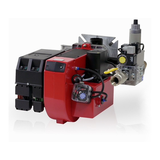
- Page 3 DESCRIPTION COMPONENTS 1. Cover,inspection glass 7. Air damper 13. Motor 2. Air pressure switch 8. Air intake Ionization electrode 3. Air adjustment 9. Ignition electrode 15. Transformer 4. Inner assembly adjustment 10. Control box 16. Inner assembly (not town gas) 11.
-
Page 4: Technical Data
TECHNICAL DATA Type designation BG 300 DIMENSIONS Length of burner tube Measure A Measure B Standard ø120 Long design ø120 Town gas ø140 The above dimensions are max. measurements. Depending on the compo- nents used, the measurements may vary. OUTPUT RANGE... - Page 5 TECHNICAL DATA DIMENSIONS OF FLANGE ø120 172 215 29 95-01...
- Page 6 Required over 1200 kW according 4. Pressure gauge with shut-off cock 10. Gas burner control to EN 676. 5a. Gas pressure switch, mini 5b. Gas pressure switch, maxi When Bio gas is used, Bentone shall always be contacted. 172 415 04 03-01...
- Page 7 MOUNTING ON THE BOILER Remove the combustion unit from the REMOVAL OF FAN HOUSE UNIT INSTALLATION EXAMPLE burner. Fit the enclosed flange and FROM BURNER. Connect the gas to the burner by gasket to the boiler.If new fixing holes Loosen the screws. Swing out the fan means of the ball valve.
- Page 8 ELECTRIC EQUIPMENT GAS BURNER CONTROL: LGB21/LMG21 WIRING DIAGRAM If there is no plug-in contact (X2) on the boiler, connect to the contact enclosed. In case the twin thermostat is in series on incoming phase L1, a loop between the terminals T1 and T2 is necessary.
- Page 9 ELECTRIC EQUIPMENT CONTROL DIAGNOSIS UNDER FAULT CONDITIONS AND LOCKOUT INDICATION GAS BURNER CONTROL: LMG ... Operating concept • Burner control has initiated lockout • Reset > Red fault LED on Press lockout reset button for 0.5 ...3 s • Diagnosis of cause of fault - Wait >10 s - Press lockout reset buttonj for >3 s - Read blink code of red fault LED...
- Page 10 MEASURES AND CHECKS BEFORE START-UP, 1-STAGE BURNER LEAKAGE CONTROL INNER ASSEMBLY Ensure that the ignition and ionisa- tion electrodes are correctly adjus- ted. The sketch shows the correct measurements. GAS QUALITY Ensure that the burner head is meant for the gas quality to be used (see fig.).
- Page 11 MEASURES AND CHECKS BEFORE START-UP INNER ASSEMBLY Town gas INNER ASSEMBLY Natural gas, LPG Natural gas INNER ASSEMBLY Biogas (UV-detector) 172 205 78 98-01...
- Page 12 DETERMINATION OF GAS VOLUME FOR THE INSTALLATION Specifications on natural gas, town Net calorific value gas and bio gas vary. For more exact information please contact the gas Gas quality kWh/Nm kJ/Nm kcal/Nm distributor. Natural gas 10.3 37 144 8 865 Propane 26.0 93 647...
- Page 13 ADJUSTMENT OF MULTI-BLOC, MB-DLE 405-420 Max. inlet pressure: 360 mbar. Adjustable governor pressure: 405 - 412 S50 = 4 - 50 mbar 415 - 420 S20 = 4 - 20 mbar 415 - 420 S50 = 20 - 50 mbar Solenoid valve: Slow opening valves with adjustable start load and max.
-
Page 14: General Instructions
GENERAL INSTRUCTIONS ADJUSTMENT OF BURNER SERVICE Service should only be carried out by The burner is from the factory pre-set A general rule is that the lower capa- qualified personnel. Replacement to an average value that must then be city the smaller the opening between parts should be of the same make adjusted to the boiler in question. - Page 15 GENERAL INSTRUCTIONS, 1-STAGE BURNER AIR ADJUSTMENT Loosen the stop screw and turn the knob along the scale to the desired position and tighten the screw. Check the air adjustment by making a flue gas analysis. ADJUSTMENT OF BRAKE PLATE Loosen the screw on the adjust- ment device.
- Page 16 GENERAL INSTRUCTION ADJUSTEMNT OF MAX. GAS PRES- ADJUSTMENT OF AIR PRESSURE FLAME MONITORING AND MEASU- SURE SWITCH SWITCH REMENT OF IONISATION CURRENT The burner is equipped with a max. gas The air presure switch should stop the The burner is monitored according to pressure switch only on request.
- Page 17 HANDING OVER OF THE INSTALLATION Make repeated start attempts to FAULT LOCATION, FUNCTIONAL ensure that the adjustments func- TROUBLES tion. Trouble free operation is dependent on three factors: electricity, gas and air Close the ball valve during opera- supply. Should there be any changes tion to check that the gas switch in the ratio between these three factors switches off at the set value.
- Page 18 FAULT LOCATION GUIDE Gas burner The basis for trouble free operation can only be ensured To facilitate fault location we have drawn up a scheme by the correct combined effect of the three factors: showing the most frequent faults in a gas burner instal- electricity, gas flow and combustion air.
- Page 19 CAUSE REMEDY The cable shoes have bad contact Improve the contact The ignition cables are damaged Replace The ignition transformer is damaged, no voltage on the Replace the transformer secondary side The ignition cable and the ionisation cable have been Change transposed.
- Page 20 CAUSE REMEDY Voltage lower than 185 V Contact the electricity authorities. The ignition electrodes are disturbing the ionisation Adjust the ignition electrodes, repole the ignition transfor- current mer if necessary. Bad earthing Arrange for proper earthing. Phase and neutral transposed See wiring diagram and change.
- Page 21 CAUSE REMEDY The ambient temperature of the gas relay is too high Heat insulate, max. 60° C. The ignition spark is too weak Check the transformer Bad combustion Bad draught conditions Check the chimney The flue gas temperature is too high The boiler is overloaded.
-
Page 22: Declaration Of Conformity
(name, type or model, batch or serial number, possibly sources and number of items) BG 100, BG 150, BG 200, STG 120, STG 146, BG 300,BG 300LN, BG 400, BG 400LN BG 450,BG 450LN, ......................................
Need help?
Do you have a question about the bg 300 and is the answer not in the manual?
Questions and answers