Sign In
Upload
Manuals
Brands
Bentone Manuals
Burner
BG 950
Bentone BG 950 Manuals
Manuals and User Guides for Bentone BG 950. We have
5
Bentone BG 950 manuals available for free PDF download: Installation And Maintenance Instruction
Bentone BG 950 Installation And Maintenance Instruction (148 pages)
Brand:
Bentone
| Category:
Burner
| Size: 12.3 MB
Table of Contents
Table of Contents
3
1 General Information
5
Safety Instructions
5
Actions to Take if You Smell Gas
6
Burner Servicing Schedule
7
Component Replacement Intervals
7
Delivery Check
7
2 Technical Data
8
Burners Are Intended for Use at
8
Dimensions
8
Description BG
16
Description BG
18
3 General Instruktions
20
General Instructions
20
Operating Instructions
20
Instructions
20
Inspection and Maintenance
20
Start up
20
Commissioning of Installation
20
4 Installation
21
Delivery Check
21
Preparations for Installation
21
Gas Supply
21
Electric Connection
21
Skeleton Diagrams
22
Fitting the Burner to the Boiler
23
Handling and Lifting Instruction
24
Inspection of Gas Nozzle before Commissioning
25
5 Setting the Burner
26
Setting the Combustion Assembly
26
Setting the Air Damper
26
Setting the Gas Damper
27
Calculating the Quantity of Gas Supplied
29
6 Service
30
Servicing the Combustion Assembly
30
Servicing Air Dampers
31
Replacement of Damper Motor, Air
32
Bg550/650
33
Replacement of Damper Motor, Gas
34
Flame Monitoring and Ionisation Current Check
35
Gas Nozzle BG 550/650
37
Gas Nozzle BG 550LN
37
Gas Nozzle BG 950
38
UV Detector
40
Setting the Air Pressure Switch
41
Setting the Min. Gas Pressure Switch
42
Setting the Max. Gas Pressure Switch
43
Vibration
44
7 Handing over of the Installation
45
8 Fault Location, Functional Troubles
45
9 Regulators
46
10 Damper Motors
47
SQN Damper Motor
47
SQM Damper Motor
49
11 Gas Train
51
DMK Gas Butterly Damper
51
Multi-Block Vgd40
53
12 Electric Equipment
63
Safety System
63
Wiring Diagram
64
Wiring Diagram RWF 50:3
65
Wiring Diagram RWF 50:2
66
Wiring Diagram Jumo 316
67
List of Components
68
Components, Electrical Cabinet
68
13 LMV37 Automatic Control Unit
69
System Structure/Function Description
69
General Information
70
Technical Data Basic Unit LMV37.4
70
Connection and Internal Diagram
75
14 Operation
77
LMV37 Automatic Control Unit
77
List of Phase Displays
79
Automatic Control Unit Levels
80
Setting the Automatic Control Unit
85
Backup and Restore
104
Fault Status Message, Display of Errors and Info
108
Dispaly Message of Info
114
Resetting the Automatic Control Unit
115
Manual Output
116
15 Parameter List ________________________________________________________117
127
16 Error Code List
127
17 Declaration of Conformity ______________________________________140
142
18 General Instruction for Gasburner
142
Advertisement
Bentone BG 950 Installation And Maintenance Instruction (58 pages)
Brand:
Bentone
| Category:
Burner
| Size: 1.51 MB
Table of Contents
Table of Contents
2
Description
5
Warning
5
2-Stage
6
Modulating
7
Technical Data
8
Dimensions
8
Output Range
9
Working Field
10
Skeleton Diagrams
11
2-Stage or Modulating Burners
11
Mounting of the Burner
12
Inspection of Gas Assembly
12
Adjustment of the Position of the Shrouded Disc in the Blast Tube
12
Electric Equipment
13
Wiring Diagram LGB22/LMG22/LME22 (BG550/BG650) 2-Stage
13
List of Components LGB22/LMG22/LME22 (BG550/BG650) 2-Stage
14
Function LGB22/LMG22/LME22
14
Wiring Diagram LMG22/LME22 (BG550/BG550LN/BG650) Modulating
15
List of Components LMG22/LME22 (BG550/BG550LN/BG650) Modulating
16
Function LMG22/LME22
16
Wiring Diagram LMG22 (BG550/BG550LN/BG650) Modulating with R316
17
List of Components LMG22 (BG550/BG550LN/BG650) Modulating with R316
18
Function LMG22
18
Control Diagnosis under Fault Conditions and Lockout Indication
19
Gas Burner Control: LGB
19
Control Diagnosis under Fault Conditions and Lockout Indication
20
Gas Burner Control: LMG
20
Control Program When Disruption; Disruption Display
21
Gas Burner Control: LME
21
Wiring Diagram LFL1
23
List of Components LFL1
24
Function LFL1
24
Wiring Diagram LFL1
25
List of Components LFL1
26
Function LFL1
26
Wiring Diagram LFL1
27
List of Components LFL1
28
Function LFL1
28
Wiring Diagram LFL1
29
List of Components LFL1
30
Function LFL1
30
Control Programme under Fault Conditions and Lockout Indication LFL1
31
Technical Data LFL1
31
Measures and Checks before Start-Up
32
2-Stage or Modulating Burners
32
Inner Assembly
33
Inner Assembly BG 550LN
34
Determination of Gas Volume for the Installation
35
Example How to Calculate the Gas Volume (Natural Gas)
35
Gas Solenoid Valve MVD
36
Operation and Assembly Instructions
37
Double Solenoid Valve Type DMV-D
37
Operation and Assembly Instructions
40
Gas Pressure Regulator Type FRS
40
Multi-Bloc, Mb-Zrdle 405 - 420 B01
42
Flow Adjustment 2-Stage Design
43
Adjustment of Governor
43
Adjustment of Start Gas Flow
43
Multi-Bloc, Mb-Vef 412 - 425 B01
44
View
44
Technical Data
45
Mounting Instruction - Impulse Lines PL, PF and Pbr
45
Adjustment Possibilities
45
Damper Motor 2-Stage
46
Air Adjustment
46
Releasing Button
46
Damper Motor Modulating
47
Air Adjustment
47
Releasing Button
47
General Instructions
48
Adjustment of Burner
48
Service
48
Flame Monitoring and Measurement of Ionisation Current
49
UV-Detector
50
Adjustment of Air Pressure Switch
51
Adjustment of Min. Gas Pressure Switch
51
Adjustment of Max. Gas Pressure Switch
51
Leakage Control, Dungs Vps 504 Series 2
52
Technical Data
52
Programme Sequence
52
Program Sequence Schedule
53
Electrical Connection VPS 504 Series 02
53
Handing over of the Installation
54
Fault Location, Functional Troubles
54
Declaration of Conformity
55
Fault Location Guide
56
Gas Burner
56
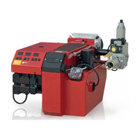
Bentone BG 950 Installation And Maintenance Instruction (52 pages)
Brand:
Bentone
| Category:
Indoor Fireplace
| Size: 8.84 MB
Table of Contents
Table of Contents
3
General Information
4
Delivery Inspection
4
Safety
4
What to Do if You Smell Gas
5
Technical Data
6
Dimensions BFG 1-2 H3
6
Capacity Range
7
Gas Categories, Approved Gases
7
Technical Specification
7
Model BFG 1-2 H3
8
Working Field
8
Setting for Nozzle Assembly and Air Damper
9
Components
10
Skeleton Diagram 2-Stage Burner, Biogas
12
Adjusting the Gas Train
13
Electric Equipment
14
Safety System
14
Wiring Diagram
14
Function LME
15
Control Program at Faults; Fault Mode Indicator LME
16
Installation
18
General Instructions
18
Instructions
18
Inspection and Maintenance
18
Preparation for Assembly
18
Gas Supply
18
Electric Connection
18
Mounting
19
Hole Pattern
19
Burner Installation
19
Gas Connections
19
Electric Connection
19
Gas Quality
20
Aerating
20
Tightness Control
20
Calculation of Gas Flow
21
Settings
22
Brake Plate Adjustment
22
Air Adjustment
22
Startup
23
Control of Combustion
23
Setting the Air Pressure Switch
24
Setting the Gas Pressure Switch, Min
25
Double Solenoid Valve DMV-DLE
26
Technical Data
26
DMV-Dle 512-520/11
27
DMV-Dle 525/11
27
Gas Solenoid Valve MVD 210/5 / MVD 215/5
29
Gas Pressure Regulator
31
Leakage Control VPS 504
33
Technical Data
33
Program Sequence
33
Electrical Connection
34
Service
35
Burner Service Schedule, Gas
35
Component Replacement Intervals
35
Combustion Device
36
Fan Motor Replacement
37
Air Intake and Suction Cone
38
Fan Wheel
40
Electrical Package
41
Control Of Flame Monitoring And Ionization Current
43
Handing over of the Installation
45
Troubleshooting
46
Service- and Inspection Protocol
48
Advertisement
Bentone BG 950 Installation And Maintenance Instruction (44 pages)
Brand:
Bentone
| Category:
Burner
| Size: 2.89 MB
Table of Contents
Table of Contents
3
Service
3
What to Do if You Smell Gas
3
General
4
Important to Remember
4
Safety Instructions
6
Delivery Check
6
Technical Data
7
Dimensions
7
Dimension of Lange
7
Capacity Range
8
Burner Speciication
8
Description BG 700/800/950
10
General Instruktions
12
General Instructions
12
Operating Instructions
12
Instructions
12
Inspection and Maintenance
12
Start up
12
Commissioning of Installation
12
Installation
13
Delivery Check
13
Preparations for Installation
13
Gas Supply
13
Electric Connection
13
Skeleton Diagrams
14
Multi-Bloc MB-DLE405-412
14
Electritrical Connection MB-DLE405-412
14
16 4.1.2 Functional Description of Gas Low
16
Operating Method of Valve-Regulator Combina- Tion on Valve V1
16
Operating Method of Valve V2
16
Min. Opening (Residual Stroke) of Valve
16
MM)
16
Closing Function
16
Multi-Bloc MB-VEF 407-412
17
Multi-Bloc MB-VEF 415-420
17
Multi-Bloc MB-VEF425
18
Electritrical Connection MB-VEF 407-425
18
Mounting of the Burner
19
Setting the Combustion Assembly
19
Wiring Diagram LFL1
20
List of Components LFL1
21
Funktion LFL1
22
Control Programme under Fault Conditions and Lockout Indication LFL1
23
Measures and Checks before Start-Up
24
2-Stage or Modulating Burners
24
Gas Nozzle BG 700/800
25
Gas Nozzle BG 950
25
Determination of Gas Volume for the Installation
26
Example How to Calculate the Gas Volume (Natural Gas)
26
Multi-Bloc, MB-VEF 420-425
27
Technical Data
28
Mounting Instruction - Impulse Lines P
28
Adjustment Possibilities
28
F Och P Br
28
Multi-Bloc, Mbd-Le 405-410
29
Damper Motor Modulating
30
Air Adjustment
30
Releasing Button
30
General Instructions
31
Adjustment of Burner
31
Service
31
Flame Monitoring and Measurement of Ionisation Current
32
UV-Detector
32
Adjustment of Air Pressure Switch
33
Adjustment of Min. Gas Pressure Switch (Option)
33
Adjustment of Max. Gas Pressure Switch (Option)
33
Handing over of the Installation
34
Fault Location, Functional Troubles
34
Fault Location Guide
35
Gas Burner
35
Bentone BG 950 Installation And Maintenance Instruction (40 pages)
Brand:
Bentone
| Category:
Burner
| Size: 3.82 MB
Table of Contents
Table of Contents
4
Description
6
Components
6
Components
7
Warning
8
Safety Directions
8
Acceptance Inspection
8
Preparations for Installation
8
Technical Data
9
Type Designation BG950
9
Dimensions
9
Out Range
9
Capacity Chart According to en 676
9
Declaration of Concordance/Conformity
10
Skeleton Diagrams
11
Mounting of the Burner
12
Electric Equipment
13
Wiring Diagram LFL 1
13
List of Components with Ionization Electrode
14
Function
14
Control Programme under Fault Conditions and Lockout Indication LFL1
15
Technical Data LFL1
15
Measures and Checks before Start-Up
16
2-Stage or Modulating Burners
16
Inner Assembly
17
Determination of Gas Volume for the Installation
18
Example How to Calculate the Gas Volume (Natural Gas)
18
Multi-Bloc
19
View
19
Mb-Vef 412 - 425 B01
19
Mbc 1900 - 3100 Vef
20
Technical Data
21
Mounting Instruction - Impulse Lines P
21
Adjustment Possibilities
21
L -P F
21
Double Solenoid Valve Gas-Air-Ratio Control Type MBC
22
Nominal Diameters DN 65 - DN 125
22
Mbc
23
Mounting
24
Installation of Pulse Lines
24
Setting the Pressure Controller
25
Adjustment of Gas Flow
26
Damper Motor, Air Volume
26
Releasing Button
26
General Instructions
27
Adjustment of Burner
27
Service
27
General Instruction
28
Flame Monitoring and Measurement of Ionisation Current
28
UV-Detector
28
Adjustment of Air Pressure Switch
29
Adjustment of Min. Gas Pressure Switch
29
Adjustment of Max. Gas Pressure Switch
29
Gas Pressure Switch, Air Pressure Switch
29
Leakage Control, Dungs Vps 504 Series 2
30
Technical Data
30
Programme Sequence
30
Program Sequence Schedule
31
Electrical Connection VPS 504 Series 02
31
Handing over of the Installation
32
Fault Location, Functional Troubles
32
Fault Location Guide
33
Gas Burner
33
Advertisement
Related Products
Bentone BG 950i M
Bentone BG 950 M
Bentone BG 300-2
Bentone BG 800
Bentone BG650M
Bentone BG550-2
Bentone BG650-2
Bentone BG 650
Bentone BG 400-2
Bentone BG 300 M
Bentone Categories
Burner
Indoor Fireplace
Industrial Equipment
Furnace
Portable Generator
More Bentone Manuals
Login
Sign In
OR
Sign in with Facebook
Sign in with Google
Upload manual
Upload from disk
Upload from URL