Table of Contents
Advertisement
Quick Links
Instructions
™
XM
Mix Manifold Kits
For mixing two component reactive materials with XM plural-component proportioners.
Not for use on mechanical proportioners.
For professional use only.
Important Safety Instructions
Read all warnings and instructions in this
manual before using the equipment.
Save these instructions.
7250 psi (50 MPa, 500 bar) Maximum Working Pressure
160°F (71°C) Maximum Fluid Temperature
For Model information and Agency Approvals, see page 2.
Mix Manifold and Remote Carriage
312749K
EN
\r_312359_312749_13.ai
Advertisement
Table of Contents

Related Manuals for Graco XM 255684


Summary of Contents for Graco XM 255684
- Page 1 Instructions ™ Mix Manifold Kits 312749K For mixing two component reactive materials with XM plural-component proportioners. Not for use on mechanical proportioners. For professional use only. Important Safety Instructions Read all warnings and instructions in this manual before using the equipment. Save these instructions.
-
Page 2: Table Of Contents
Overview ........11 Graco Standard Warranty ......34 Installation . -
Page 3: Warnings
Warnings Warnings The following warnings are for the setup, use, grounding, maintenance, and repair of this equipment. The exclamation point symbol alerts you to a general warning and the hazard symbols refer to procedure-specific risks. When these symbols appear in the body of this manual or on warning labels, refer back to these Warnings. Product-specific hazard symbols and warnings not covered in this section may appear throughout the body of this manual where applicable. - Page 4 Warnings WARNING SKIN INJECTION HAZARD High-pressure fluid from gun, hose leaks, or ruptured components will pierce skin. This may look like just a cut, but it a serious injury that can result in amputation. Get immediate surgical treatment. • Do not spray without tip guard and trigger guard installed. •...
-
Page 5: Important Isocyanate (Iso) Information
Important Isocyanate (ISO) Information Important Isocyanate (ISO) Information Isocyanates (ISO() are catalysts used in two component materials. Isocyanate Conditions Keep Components A and B Separate Spraying or dispensing fluids that contain isocyanates creates potentially harmful mists, Cross-contamination can result in cured material in vapors, and atomized particulates. -
Page 6: Moisture Sensitivity Of Isocyanates
Moisture Sensitivity of Changing Materials Isocyanates NOTICE Changing the material types used in your equipment Exposure to moisture (such as humidity) will cause ISO requires special attention to avoid equipment damage to partially cure, forming small, hard, abrasive crystal and downtime. that become suspended in the fluid. -
Page 7: Component Identification
Component Identification Component Identification Manifold 255684 (shown mounted on an XM proportioner) ti38992a . 1: Typical Installation Ref. Description A Material Inlet B Material Inlet Pressure Gauge Solvent Inlet Mix Manifold Outlet Remote Recirculation Ports Restriction Valve A Shutoff Valve B Shutoff Valve Solvent Shutoff Valve Solvent Check Valve... -
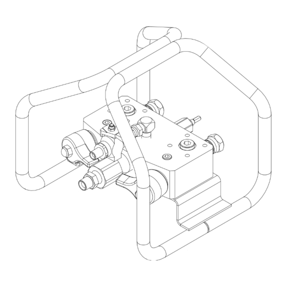
Page 8: Remote Mix Manifold Conversion Kit 256980
Component Identification Remote Mix Manifold Conversion Kit 256980 ti38993a . 2: Typical Installation Ref. Description A Check Valve Inlet B Check Valve Inlet Remote Manifold Carriage Mix Manifold (sold separately) Mounting Fasteners Adapter Fittings (shipped loose) Proportioner Mounted Restrictor Valve 312749K... -
Page 9: Remote Recirculation Kit 273185
Component Identification Remote Recirculation Kit 273185 ti38995a . 3: Typical Installation Ref. Description Ref. Description Adapter Fitting (shipped loose) A Material Recirculation Outlet A Remote Recirculation Valve B Material Recirculation Outlet B Remote Recirculation Valve Recirculation Hose Extension Solvent Hose Extension Recirculation Hose Shutoff Valve Hose Adapter Fitting Recirculation Tube... -
Page 10: Typical Installation
Component Identification Typical Installation Blue Green ti38997a . 4: Typical Installation Ref. Description Ref. Description A Material Recirculation Outlet Recirculation Hose B Material Recirculation Outlet Solvent Hose Recirculation Tube A Recirculation Valve Bushing (shipped loose) B Recirculation Valve Adapter Fitting (shipped loose) Solvent Pump Solvent Hose Extension Integrator Hose... -
Page 11: Overview
Overview Overview XM plural-component sprayers can mix most two The resin and hardener enter the manifold through the component epoxy and urethane protective coatings. manifold inlet ports. The “A” material flows through the When using quick-setting materials (less than 10 minute manifold to the material outlet port. -
Page 12: Installation
For assistance in setting up a plural component sprayer, manifold (BD) to the remote carriage (BC). contact your Graco distributor, to ensure that you select the proper type and size equipment for your system. NOTE: See Mounting Without Carriage on page 13 if not using the remote carriage. -
Page 13: Mounting Without Carriage
Installation Mounting Without Carriage Remote Recirculation Kit (273185) To mount the bare manifold, drill four holes in the mounting surface, and secure with four 5/16-18 x 1/2 in. (50 mm) screws. See the following illustration for details and dimensions. 6.38 in. (162.05 mm) 1.44 in. -
Page 14: Grounding
• Mix manifold and solvent flush system: use only a Graco approved grounded solvent hose. Not all Flush Before Using Equipment heated hoses are grounded, and the mix manifold primary ground is through the solvent hose. Ensure... -
Page 15: Operation
Operation Operation Prime Remote Mix Manifold 4. Use manual pump run mode to run “A” side. See your XM operation manual. Prime A and B Material Hoses 5. Press as needed to prime. If a remote recirculation kit is not installed, monitor the container to avoid overflow. -
Page 16: Prime Solvent Hose
Operation Prime Solvent Hose 5. Disengage the trigger lock and trigger the gun into a grounded pail. Use a pail lid with a hole to dispense through. Prime A and B Material Hoses NOTE: To prevent splash back, use a rag to seal around the hole and gun. -
Page 17: Dispensing And Spraying
Operation Dispensing and Spraying Pressure Relief Procedure 1. Close the solvent shutoff valve (AK). Close the remote recirculation valves (CH, CJ) if equipped. Follow the Pressure Relief Procedure whenever you see this symbol. This equipment stays pressurized until pressure is ti38460a manually relieved. - Page 18 Operation 7. Disengage trigger lock. 9. Engage the trigger lock. 8. Hold a metal part of the gun firmly to a grounded 10. Flush mixed material hoses, mixer, and gun. See Flush Mixed Material on page 19. metal pail with a splash guard in place. Trigger gun to relieve pressure in material hoses.
-
Page 19: Flush Mixed Material
Operation Flush Mixed Material 3. Make sure shutoff handles (AH, AJ) and remote recirculation valves (CH, CJ) are closed. NOTE: The valve handles point at each other in the closed position. 4. Open solvent shutoff valve (AK). To avoid fire and explosion, always ground equipment and waste container. -
Page 20: Empty And Flush Remote Mix Manifold
Operation 9. Hold the metal part of the gun firmly to a grounded 3. Close the shutoff valves (AH, AJ) and open the metal pail with lid in place. Trigger gun until all fluid remote recirculation valves (CH, CJ) if equipped. If pressure is relieved. -
Page 21: Volume Balancing The Mix Manifold
Operation Volume Balancing the Mix Adjust B Mix Manifold Restriction on XM Proportioners While Spraying Manifold Proportioner Mounted Mix Manifold When the mix manifold is remote mounted ratio errors can occur between the proportioner and the mix Adjust the restriction stem on the mix manifold to manifold;... -
Page 22: Hose Selection For Feeding A Remote Mix Manifold
Operation Hose Selection for Feeding a Table 2: Hose Selection by Pressure Drop Pressure drop per Pressure Drop per Remote Mix Manifold Hose ID 50 ft section per 15.24 meter section (in.) 1000 cps at 1 per 1000 cps at 1 Hoses should be sized to match the hose volume ratio gal/min. -
Page 23: Troubleshooting
Troubleshooting Troubleshooting 1. Follow the Pressure Relief Procedure on page 17. 2. Check all possible causes and solutions in the troubleshooting chart before disassembling the manifold. Problem Cause Solution Clean inlet; remove obstruction. See Clean Little or no resin output Fluid inlet is plugged Mix Manifold Outlet, page 26. -
Page 24: Repair
Repair Repair 4. Clean all parts thoroughly in a compatible solvent. Use a soft bristle brush to clean the manifold passageways. Remove Restrictor Follow the Pressure Relief Procedure on page 17 1. Note number of turns from open to closed position. when you stop spraying and before cleaning, Remove restrictor housing (19) from manifold (1). -
Page 25: Assemble Restrictor
Repair Assemble Restrictor Assemble Cartridge Assembly 1. Insert seat (14) with larger tapered end facing up in 1. Apply blue thread lock to external threads of manifold (1). cartridges (11) and install in manifold with stem backed out fully counter-clockwise. Place wrench on cartridge flats and torque to 125 ft-lbs (170 N•m). -
Page 26: Maintenance
Maintenance Maintenance Clean Static Mixers 2. Pull “V” screen (28) and retainer o-ring (29) straight up and out with a needle nose pliers. Typically, two static mixer housings (S, Part No. 262478) 3. Clean or replace screen (28). Reinstall screen (28) are connected to the static mixer adapter (V) on the and white plastic o-ring (29) with tool 15T630 integrator hose (L). -
Page 27: 255684 Mix Manifold
Part Part 255684 Mix Manifold Detail A 11, see Detail A Apply lithium grease. Apply anaerobic pipe thread sealant. Apply blue thread lock to external threads. Torque to 125 ft-lb (170 N•m). Plastic assembly tool for (28, 29, 11d) included in repair kit 256238. U-cup open lips face spring. - Page 28 Part 255684 Mix Manifold Parts List Ref. Part Descriptions Qty. 15M229 BLOCK, manifold 2† 117558 SPRING, compression 3† 101947 BALL, solvent check 15E367 ELBOW, street, lapped 214037 VALVE, ball; see manual 306861 15R378 TUBE, injector, hardener 15R067 PIPE, outlet, mixer manifold 255747 CARTRIDGE, valve, shutoff check;...
-
Page 29: 256980 Remote Mix Manifold Conversion Kit
Part 256980 Remote Mix Manifold Conversion Kit 33 or 116 or 117 Mix manifold 255684 is not included (purchase separately). See page 27 for parts. ti23371b Face down. “B” outlet to hose. 312749K... - Page 30 Part 256980 Remote Mix Manifold Kit Parts List Ref. Part Descriptions Qty. 117623 NUT, cap 3/8-16 unc 15R380 HANDLE, green 15J916 HANDLE, blue 156684 UNION, adapter 32‡ 158491 NIPPLE, 1/2 npt 33‡ 159239 NIPPLE, pipe; 1/2 x 3/8 npt 45 162449 NIPPLE;...
-
Page 31: 273185 Remote Recirculation Kit
Part 273185 Remote Recirculation Kit 273185 Remote Recirculation Kit Parts List Mix Manifold 255684 is not included Ref. Part Descriptions Qty. (purchase separately). 156684 FITTING, union, adapter Remote Mix Manifold 256980 is not included 156823 FITTING, union, swivel (purchase separately). 129347 BUSHING, strain relief, 3/4-npt 100840... -
Page 32: Accessories
Accessories Accessories 255747, Shutoff Check Valve Cartridge 162024, Adapter Between Mix Tubes Assembly 3/8 npt f x f; 7250 psi (50 MPa, 500 bar). See manual 313343 for parts. B-side Screen 255278, Complete High Flow Sever Duty For low viscosity fluids only. Shutoff Check Valve 185416 - STRAINER, 40m Includes housing, screws, and o-ring for recirculation or... -
Page 33: Technical Specifications
Technical Specifications Technical Specifications XM Remote Mix Manifold Kit, XM Remote Recirculation Kit Metric Maximum working pressure 7250 psi 50 MPa, 500 Bar Maximum fluid temperature 160 °F 71 °C 1/2 in. npsm union with nipple adapters for 1/2 in., 3/8 in., A and B Material Inlet or 1/4 in. -
Page 34: Graco Standard Warranty
With the exception of any special, extended, or limited warranty published by Graco, Graco will, for a period of twelve months from the date of sale, repair or replace any part of the equipment determined by Graco to be defective.
Need help?
Do you have a question about the XM 255684 and is the answer not in the manual?
Questions and answers