AGA Falcon Mercury 1200 Induction User's Manual & Installation Instructions
Hide thumbs
Also See for Falcon Mercury 1200 Induction:
- User's manual & installation instructions (48 pages)
Table of Contents
Advertisement
Quick Links
Advertisement
Table of Contents

Related Manuals for AGA Falcon Mercury 1200 Induction


Summary of Contents for AGA Falcon Mercury 1200 Induction
- Page 1 USER GUIDE & INSTALLATION INSTRUCTIONS Mercury 1200 Induction...
- Page 2 SLOW BAKED LEG OF LAMB METHOD 1. Preheat the oven to 220 ¡C (for a conventional oven), 200 ¡C (for a fan oven) or gas mark 7. 2. Pull the small sprigs off the rosemary branches and set aside with the garlic. 2.
-
Page 3: Table Of Contents
Contents Before You Start... Troubleshooting Installation and Maintenance Installation Peculiar Smells Dear Installer Ventilation Safety Requirements and Regulations Personal Safety Provision of Ventilation Hob Care Location of Cooker Cooker Care Positioning the Cooker 2. Cooker Overview Moving the Cooker The Hob Fitting the Flue and Vent The Ovens Fitting the Side Panel and Obscuring Trims 23... -
Page 5: Before You Start
1. Before You Start... DocNo.015-0306 - Introduction - Induction - Single cavity Thank you for buying a this cooker. It should give you many Personal Safety years of trouble-free cooking if installed and operated Important information for pacemaker and implanted correctly. -
Page 6: Hob Care
Cooking high moisture DO NOT use water on grease fires and never pick content foods can create up a flaming pan. Turn off the controls and then a ‘steam burst’ when the smother a flaming pan on a surface unit by covering oven door is opened. -
Page 7: Cooker Overview
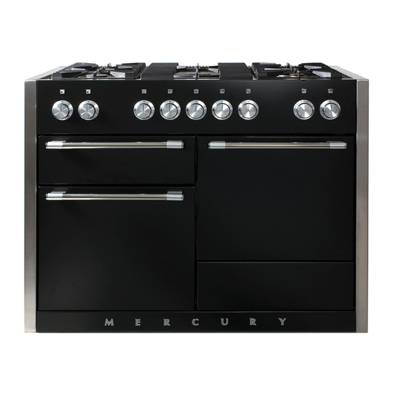
DocAUS.020-0004 - Overview - 110DF - Elan 2. Cooker Overview Fig.2-1 The 1200 induction cooker (Fig.2-1) has the following Fig.2-2 features: 5 induction cooking zones A control panel A glide-out grill Main multi-function oven Fan oven Storage drawer The Hob Use only pans that are suitable for induction hobs. - Page 8 The very best pans have bases that are very slightly curved Fig.2-3 up when cold (Fig.2-3). If you hold a ruler across the bottom you will see a small gap in the middle. When they heat up the metal expands and lies flat on the cooking surface. Make sure that the base of the pan is clean and dry to prevent any residue burning onto the hob panel.
- Page 9 Automatic Heat-up, A Auomatic Heat-up Time at Power level 100% (min:sec) This function is available on all of the cooking zones. It allows rapid heating up of the element to bring the selected 0:48 cooking zone up to temperature. Once the zone is at the 2:24 required cooking temperature the power level will reduce automatically to the preset level.
- Page 10 The maximum time this setting can be used is 2 hours. To Fig.2-8 increase the heat, just turn the control knob to the required A & B linked D & E linked level. Power Boost Setting, P All of the induction cooking zones have Power Boost available, activated by turning the control knob clockwise until [P ] is shown on the hob control display.
- Page 11 The Glide-out Grill Fig.2-9 CAUTION: Accessible parts may be hot when the grill is in use. Young children should be kept away. CAUTION: This appliance is for cooking purposes only. It must not be used for other purposes, for example room heating. Open the door and pull the grill pan carriage forward using the handle (Fig.2-9).
-
Page 12: The Ovens
The Ovens Fan oven cooking is particularly suitable for baking on several shelves at one time and is a good ‘all-round’ function. It may References to ‘left-hand’ and ‘right-hand’ ovens apply as viewed be necessary to reduce the temperature by approximately from the front of the appliance. - Page 13 Browning Element Function This function uses the element in the top of the oven To thaw small items in the oven without Defrost only. It is a useful function for the browning or heat finishing of pasta dishes, vegetables in sauce, A full cooking function, even heat shepherds pie and lasagne, the item to be browned being Fan oven...
-
Page 14: Accessories
Accessories Fig.2-16 Fig.2-17 Oven Shelves The cooker is supplied with the following: 3 standard shelves (Fig.2-16) 1 drop shelf (Fig.2-17) 1 telescopic shelf with runners (Fig.2-18) 2 sets of side supports (Fig.2-19) The oven shelves are retained when pulled forward but can Fig.2-18 Fig.2-19 be easily removed and refitted. -
Page 15: Storage
To Remove and Fit a Shelf to the Side Supports Fig.2-24 Fig.2-25 The shelf has a small kink on either side (Fig.2-23). To remove the shelf, line these up with the stops in the shelf support (Fig.2-24). Lift the rear of the shelf upward so that it will pass over the shelf stop and then pull it forward (Fig.2-25). -
Page 16: Cooking Tips
3. Cooking Tips Cooking with a Multi-function Oven General Oven Tips Remember: not all modes are suitable for all food types. The The wire shelves should always be pushed firmly to the back oven cooking times given are intended for a guide only. of the oven. -
Page 17: Cooking Table
DocNo.031-0004 - Cooking table - electric & fan single cavity 4. Cooking Table The oven control settings and cooking times given in the table below are intended to be used Top (T) AS A GUIDE ONLY. Individual tastes may require the temperature to be altered to provide a ArtNo.050-0007 preferred result. -
Page 18: Cleaning Your Cooker
5. Cleaning Your Cooker Isolate the electricity supply before carrying out any major Fig.5-1 cleaning. Allow the cooker to cool. Never use paint solvents, washing soda, caustic cleaners, biological powders, bleach, chlorine based bleach cleaners, coarse abrasives or salt. Do not mix different cleaning products – they may react together with hazardous results. -
Page 19: Glide-Out Grill
Glide-out Grill Fig.5-2 Before you remove any of the grill parts for cleaning. make sure that they are cool, or use oven gloves. The grill pan and grill tray assembly can be easily removed for cleaning. Wash the grill pan and trivet washed in hot soapy water. After grilling meats or any foods that soil, leave to soak for a few minutes in the sink immediately after use. -
Page 20: Ovens
Ovens Fig.5-6 Fig.5-7 Base Tray The ovens have a removable base tray, which can be easily removed for cleaning. Wash the base tray with a proprietary enamel cleaner. Alternatively, wash the base tray in a dishwasher. ‘Cook & Clean’ Panels The ovens have side ‘Cook &... -
Page 21: Cleaning Table
Cleaning Table Cleaners listed (Table 5-1) are available from supermarkets or electrical retailers as stated. For enamelled surfaces use a cleaner that is approved for use on vitreous enamel. Regular cleaning is recommended. For easier cleaning, wipe up any spillages immediately. Hotplate Part Finish... -
Page 22: Troubleshooting
DocNo.053-0003 - Troubleshooting - In G5 6. Troubleshooting Interference with and repairs to the hob MUST NOT The induction hob is noisy be carried out by unqualified persons. Do not try When using the induction hob there may be some to repair the hob as this may result in injury and ‘noise’... - Page 23 If there is an installation problem and I don’t get my The oven is not cooking evenly original installer to come back to fix it, who pays? Do not use a baking tray with dimensions larger than those specified in the section on ‘General Oven Tips’ . You do.
-
Page 24: Installation
INSTALLATION Check the appliance is electrically safe when you have finished. 7. Installation You will need the following equipment to complete the Dear Installer cooker installation satisfactorily: Before you start your installation, please complete the details • Multimeter (for electrical checks). below, so that, if your customer has a problem relating to •... -
Page 25: Positioning The Cooker
INSTALLATION Check the appliance is electrically safe when you have finished. Positioning the Cooker Fig.7-1 Fig.7-1 and Fig.7-2 shows the minimum recommended 33 mm 33 mm distance from the cooker to nearby surfaces. 800 mm The cooker should not be placed on a base. Above hotplate surround should be level with, or above, any adjacent work surface. -
Page 26: Fitting The Flue And Vent
INSTALLATION Check the appliance is electrically safe when you have finished. Removing the Storage Drawer Fig.7-5 Pull the drawer out to its furthest point. Push the ends of the plastic clips – down on the left-hand side, up on the right-hand side – to release the catches holding the drawer to the side runners. -
Page 27: Fitting The Side Panel And Obscuring Trims
INSTALLATION Check the appliance is electrically safe when you have finished. Fitting the Side Panel and Obscuring Fig.7-10 Trims IMPORTANT: Before fitting the side panels you must first remove the transit brackets. Loosen the two screws in the underside of the transit bracket (Fig.7-10). Slide the bracket forwards and remove. -
Page 28: Repositioning The Cooker Following Connection
INSTALLATION Check the appliance is electrically safe when you have finished. Repositioning the Cooker Following Fig.7-14 Connection If you need to move the cooker once it has been connected then you need to unplug it and, having gripped under the fascia panel and lifted the front of the cooker slightly (Fig.7-7). -
Page 29: Electrical Connection
INSTALLATION Check the appliance is electrically safe when you have finished. Electrical Connection Fig.7-16 The cooker must be installed by a qualified electrician to comply with the relevant electrical regulations, and also the local electricity supply company requirements. Current Operated Earth Leakage Breakers The combined use of your cooker and other domestic 10 mm²... -
Page 30: Final Fitting
INSTALLATION Check the appliance is electrically safe when you have finished. Final Fitting Fig.7-18 Fitting the Bottom Panel Open the left-hand oven door and make sure the storage drawer is removed. Note: For safety’s sake make sure the drawer runners are out of the way. -
Page 31: Circuit Diagrams
8. Circuit Diagrams Circuit Diagram: Hob Cooling fan activation lead Earth Induction unit Hob display ArtNo.083-0013 - IN 1200 - Circuit diagram - Mercury L(1) L(2) L(3) N4 w/br Interface w/br w/br board w/br w/br Code Description Code Colour Left-hand front element w/br White or brown Left-hand back element Right-hand back element... -
Page 32: Circuit Diagram: Ovens
Circuit Diagram: Ovens P095199 P095199 P095199 P028728 The connections shown in the circuit diagram are for single-phase. The ratings are for 230 V 50 Hz. Code Description Code Description Code Colour Left-hand MF oven control Right-hand fan oven control switch Blue Left-hand MF oven control switch Right-hand fan oven thermostat Brown Left-hand MF oven thermostat... -
Page 33: Technical Data
DocGB.103-0014 - Technical data - IN 1200 - Mercury 9. Technical Data INSTALLER: Please leave these instructions with the User. DATA BADGE LOCATION: Cooker back, serial number repeater badge below oven door opening. COUNTRY OF DESTINATION: GB, IE, FR, NL, BE, DE, AT, SE, CH. Connections Electric 230 / 400 V 50 Hz... - Page 36 Clarence Street, Royal Leamington Spa, Warwickshire, CV31 2AD, England. Tel: +44 (0) 1926 457400 Fax: +44 (0) 1926 450526 E-mail: consumers@falconappliances.co.uk...
Need help?
Do you have a question about the Falcon Mercury 1200 Induction and is the answer not in the manual?
Questions and answers