AGA GC Series Installation Instructions Manual
Gas fired cooker with aims
Hide thumbs
Also See for GC Series:
- User instructions (24 pages) ,
- Installation instructions manual (12 pages) ,
- Operating instructions manual (9 pages)
Table of Contents
Advertisement
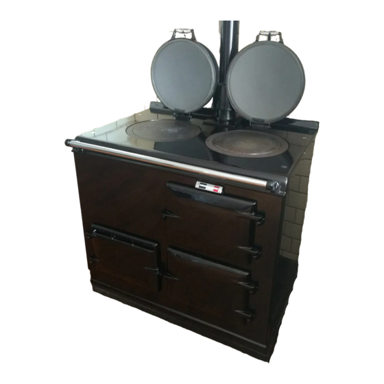
Aga Gas Fired Cooker Models
GC and GE with AIMS
Installation
Instructions
REMEMBER: when replacing a part on this appliance, use only spare parts that
you can be assured conform to the safety and performance specification that we
require. Do not use reconditioned or copy parts that have not been clearly
authorised by AGA.
PLEASE READ THESE INSTRUCTIONS BEFORE INSTALLING THIS APPLIANCE
For use in GB and IE
12/13 EINS 515930
Advertisement
Table of Contents

Related Manuals for AGA GC Series


Summary of Contents for AGA GC Series
- Page 1 Aga Gas Fired Cooker Models GC and GE with AIMS Installation Instructions REMEMBER: when replacing a part on this appliance, use only spare parts that you can be assured conform to the safety and performance specification that we require. Do not use reconditioned or copy parts that have not been clearly authorised by AGA.
-
Page 2: Table Of Contents
CONTENTS SECTION PAGE HEALTH AND SAFETY INSTALLATION TECHNICAL DATA GC & GE AIMS 5 - 6 LOCATION FLUE SYSTEM INSTALLATION PIPES AIR SUPPLY ELECTRICAL BURNER ASSEMBLY - AIMS CONTROL WIRING DIAGRAM ASSEMBLY OF BURNER - AIMS CONTROL OVEN THERMOCOUPLE TO TEST THE AIMS CONTROL HANDSET COMMISSIONING 12 - 13 INSTRUCTIONS... -
Page 3: Health And Safety
Children should be supervised to ensure that they do not play with the appliance. IMPORTANT NOTICE: PLEASE READ THE ACCOMPANYING WARRANTY. Any alteration that is not approved by AGA could invalidate the approval of the appliance, operation of the warranty and could affect your statutory rights. -
Page 4: Installation
(A further 116mm is necessary, if a left hand side gas connection is required. If the AGA is to be installed in a brick recess, then the minimum clearance should be increased by at least 10mm either side, to allow for the walls not being square and also for the natural dimensional variations found in the castings. -
Page 5: Technical Data Gc & Ge Aims
R.H. SIDE VIEW Fig. 1 DESN 515471 mm 987 889 851 679 467 1035 41 1330 756 1125 73 698 116 TECHNICAL DATA AGA GC & GE COOKER (AIMS) NATURAL G20 MAXIMUM HEAT INPUT 4.4 kW Thermostat Bypass Size Main Burner Injector... - Page 6 Fig. 2 mm 1487 889 851 679 467 1035 41 1330 756 1125 73 698 116 TECHNICAL DATA AGA GC & GE COOKER (AIMS) NATURAL G20 MAXIMUM HEAT INPUT 4.4 kW Thermostat Bypass Size Main Burner Injector Pilot Injector 7218...
-
Page 7: Location
LOCATION The location chosen for the appliance must permit the provision of a satisfactory flue and an adequate air supply. The location must also provide adequate space for servicing and air circulation around the cooker FLUE SYSTEM The following notes are intended to give general guidance:- The initial length of flue pipe from the appliance flue socket should be vertical for at least 600mm. -
Page 8: Electrical
ELECTRICAL A 3 Amp 230V-50Hz fused electrical supply is required adjacent to the appliance. External wiring to the fan unit must be installed using a 3-core heat resistant silicone sheathed cable and in accordance with the current Wiring Regulations and any local regulations which apply. The wiring should be completed as indicated: The method of connection to the mains electricity supply must facilitate complete electrical isolation of the appliance, preferably by the use of an unswitched shuttered socket outlet in... -
Page 9: Burner Assembly - Aims Control
BURNER ASSEMBLY - AIMS CONTROL A - ON/OFF CONTROL KNOB B - TEMPERATURE CONTROL KNOB C - GAS COCK D - INLET PRESSURE TEST NIPPLE E - BURNER PRESSURE TEST NIPPLE F - FLUE SAFETY DEVICE G - AIMS CONTROL KNOB H - VIEWING WINDOW Fig. -
Page 10: Assembly Of Burner - Aims Control
ASSEMBLY OF BURNER - AIMS CONTROLS SEE FIG. 3 NOTE: Prior to assembly remove controls mounting bracket from burner housing. 1. Fit gas cock to inlet supply pipe. 2. Fit burner assembly to burner housing. 3. Fix AIMS control mounting bracket to burner housing. 4. -
Page 11: To Test The Aims Control Handset
Fig. 6 DESN 515480 TO TEST THE AIMS CONTROL HANDSET Fig. 7 DESN 515481 Handset to Base Unit Signal Check/Language Selection Complete the following procedure to check the handset is communicating with the base unit and to select language option. 1. -
Page 12: Commissioning
CAUTION: BEFORE LIGHTING: ENSURE KNOB (A) IS IN THE OFF POSITION (SEE FIG. 9). ALSO ENSURE GAS SUPPLY TO COOKER IS ON, AND THE GAS SERVICE COCK (C) IS IN THE ON POSITION (SEE FIG. 3), AND THE ELECTRICAL SUPPLY TO THE AGA IS SWITCHED ON. -
Page 13: Instructions
Hand these and the operating instructions to the User for retention and instruct in the safe operation of the appliance. Finally advise the User that, for continued efficient and safe operation of the appliance it is important that adequate servicing is carried out at regular intervals recommended by the AGA Distributor or local Gas Region. -
Page 14: Burner Controls
BURNER CONTROLS Fig. 8 Fig. 9 Fig. 10 Fig. 12 Fig. 11 Fig. 13 Fig. 14 DESN 513393... - Page 16 For further advice or information contact your local AGA Specialist With AGA Rangemaster’s policy of continuous product improvement, the Company reserves the right to change specifications and make modifications to the appliance described and illustrated at any time Manufactured by...
Need help?
Do you have a question about the GC Series and is the answer not in the manual?
Questions and answers