Table of Contents
Advertisement
Quick Links
Advertisement
Table of Contents

Subscribe to Our Youtube Channel
Related Manuals for Hanwha Vision PNM-C9022RV


Summary of Contents for Hanwha Vision PNM-C9022RV
- Page 1 NETWORK CAMERA User Manual PNM-C9022RV...
- Page 2 Network Camera User Manual Copyright ©2022 Co., Ltd. All rights reserved. Hanwha Vision Trademark Each of trademarks herein is registered. The name of this product and other trademarks mentioned in this manual are the registered trademark of their respective company. Restriction Copyright of this document is reserved.
- Page 3 overview IMPORTANT SAFETY INSTRUCTIONS 22. Screen distortion could occur outside of the subject distance. 23. When accessing multi-channels (CH1 - 3), 1 or 2fps could drop from the set fps at 20fps. 1. Read these instructions. 24. While encoding, a real time fps fluctuation of ±1fps could occur. 2.
- Page 4 overview Class construction Please read the following recommended safety precautions carefully. An apparatus with CLASS construction shall be connected to a MAINS socket outlet with a ~ Do not place this apparatus on an uneven surface. protective earthing connection. ~ Do not install on a surface where it is exposed to direct sunlight, near heating equipment or heavy cold area.
-
Page 5: Table Of Contents
CONTENTS OVERVIEW Important Safety Instructions WEB VIEWER Connecting to the Camera Recommended PC Specifications Password setting Recommended Micro SD/SDHC/SDXC Login Memory Card Specifications Camera Web Viewer Setup NAS recommended specs What’s Included Optional Accessories for Installation At a Glance APPENDIX Troubleshooting INSTALLATION &... -
Page 6: Recommended Pc Specifications
overview RECOMMENDED PC SPECIFICATIONS WHAT’S INCLUDED Please check if your camera and accessories are all included in the product package. ~ CPU : Intel(R) Core(TM) i7 3.4 GHz or higher (As for each sales country, accessories are not the same.) ~ RAM : 8G or higher ~ Recommended browser: Chrome Appearance... -
Page 7: Optional Accessories For Installation
OPTIONAL ACCESSORIES FOR INSTALLATION Appearance Item Name Quantity Description You can purchase appropriate optional accessories available. Screws used for mounting your camera on the hanging Machine Screws mount, GangBox, etc. Cap Installer Used to connect the RJ45 cable. Used for dome cover disassembly, Screw bit assembly and camera installation. -
Page 8: At A Glance
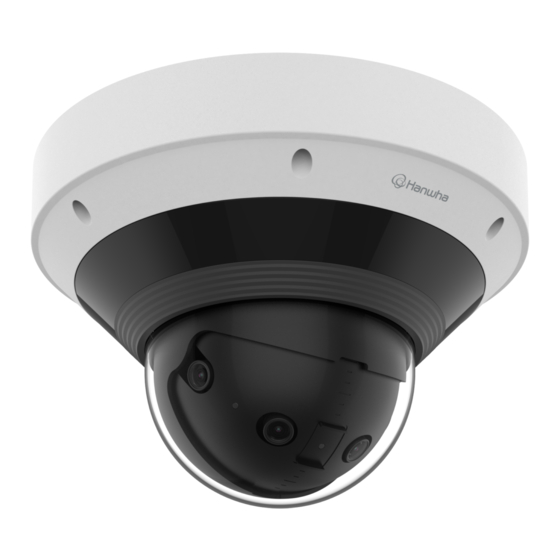
overview AT A GLANCE Components (Front Side) Appearance Item Description Lens 4 camera lenses create a panoramic image. Item Description Dome cover Case cover used to protect the lens and the main unit. Illumination Sensor Detects incoming light to control the IR LED. Camera body Body part where the camera lens and connection terminals are included. - Page 9 Components (Rear Side) Item Description This port connects power and network via PoE+ injector. PoE+ port Plug in the audio and alarm cable to this port to connect with external alarm device/ Audio/Alarm cable port microphone/speaker. Power port (DC 12 V) Port for power terminal block.
-
Page 10: Installation & Connection
installation & connection INSTALLATION 2. Loosen the fastening screw on the camera body. You don’t have to completely remove the screws. This camera is waterproof and in compliance with the IP66 spec, but the jack connected to the external cable is not. You are recommended to install this product below the edge of eaves to prevent the cable from being externally exposed. - Page 11 Inserting a Micro SD card Removing a Micro SD card Gently press down on the exposed end of the Micro SD card as shown in the diagram to eject the Micro SD 1. Remove the dome cover of the camera. card from the slot.
- Page 12 installation & connection Installation (mount plate) 1-3. Pull out necessary cables among network/power/audio/alarm cables through the hole in the mount plate. [Directly installing on ceiling] 1-1. Attach the installation template on the desired surface and drill holes for screws and cables. [Installing using pipe] 2-1.
- Page 13 2-3. Place the pipe on the mount plate. [Attaching to the unbundled adapter] 2-4. Fix the mount plate using appropriate screws. Choose and purchase a necessary one of the following options (unbundled) that is suitable to the installation site or for your convenience. 3-1.
- Page 14 installation & connection Installation (camera body and dome cover) 3. Pull the cable cover of the camera body to open it as shown in the figure below. 1. Connect the safety wire. 4. Pull out the cable bushings from the camera body. 2.
- Page 15 [Installing network/power cables] 5-5. Connect the network cable connector to the PoE+ port, and connect the power terminal block to the power port. Use a cable bushing compliant with the network cable to be connected. Camera main: use a cable with the diameter of Ø5 to 6.5 Components: use a cable with the diameter of Ø7 to 8.5 5-1.
- Page 16 installation & connection 6-3. Mount the cable bushing to the camera body. [Installing audio/alarm cables] 7. Plug the cable bushing of the provided audio/alarm cable into the camera body. 6-4. Connect the network cable jack to the PoE+ port of the camera. 8.
- Page 17 9. When all cable connections are complete, raise the cable cover and close it so that it gets stuck in the 11. Using the fastening screws on the camera body, fix the camera body to the mount plate. lock. 12. Adjust the lens to the desired direction by referring to “Adjusting the monitoring direction for the camera”.
- Page 18 installation & connection Outdoor installation Adjusting the monitoring direction for the camera When you install it outside of the building, please waterproof it with waterproof butyl rubber tape (can be purchased in stores) so that water does not leak from the gap of the cable connected to the outside. 1.
-
Page 19: Connecting With Other Device
CONNECTING WITH OTHER DEVICE Installation precautions when using the IR mode ~ <Auto1>: Optimized to evenly radiate IR light when generally mounting the camera on the wall. WiFi dongle ~ <Auto2>: Optimized to evenly radiate IR light when generally mounting the camera on the ceiling. ~ <Manual>: You can manually adjust each zone to better capture the environment where the camera is installed. - Page 20 installation & connection Connecting WiFi Power Cable Specification Camera Setup In case of DC 12 V Input: 1. Connect OTG adapter (5-pin) and WiFi dongle to the micro USB port. Wire Type (AWG) Smartphone Setup Cable Length (Max.) 11 m 18 m 1.
- Page 21 Connecting to Audio Input/Output Connecting to the I/O port box Connect the Alarm I/O cable to the corresponding port of the port box. Speaker Microphone Network Speaker Microphone Alarm Sensor 1. Connect the AUDIO IN port of the camera with the microphone or LINE OUT port of the amplifier that the microphone is connected to.
- Page 22 installation & connection To connect to an external sensor To connect to an alarm output To use as an Alarm IN: Connect one of the [ALARM I/O] port and the other terminal to the [GND] port. If devices (e.g., flashing light and siren) that exceed the voltage and current specifications are connected by using the open collector method, it may cause damage.
-
Page 23: Network Connection And Setup
network connection and setup CONNECTING THE CAMERA DIRECTLY TO A DHCP BASED DSL/CABLE You can set up the network settings according to your network configurations. MODEM CONNECTING THE CAMERA DIRECTLY TO LOCAL AREA NETWORKING Connecting to the camera from a local PC in the LAN INTERNET 1. -
Page 24: Using Device Manager
If using a Broadband Router ~ IP Address : Enter an address falling in the IP range provided by the Broadband Router. Device manager program can be downloaded from <Support>-<Online Tool> menu at Hanwha Vision website ex) 192.168.1.2~254, 192.168.0.2~254, (https://www.HanwhaVision.com). -
Page 25: Manually Registering Camera
~ Example of the Dynamic IP environment configure the IP. PNM-C9022RV - If a Broadband Router, with cameras connected, is assigned an IP address by the DHCP server 2. Click < + > at the main page of device manager. -
Page 26: Port Range Forward (Port Mapping) Setup
network connection and setup PORT RANGE FORWARD (PORT MAPPING) SETUP Setting up Port Range Forward for several network cameras ~ You can set a rule of Port Forwarding on the Broadband Router device through its configuration web page. If you have installed a Broadband Router with a camera connected, you must set the port range forwarding on the ~ A user can change each port using the camera setting screen. -
Page 27: Connecting To The Camera From A Shared Local Pc
CONNECTING TO THE CAMERA FROM A SHARED LOCAL PC 1. Run device manager. It will scan for connected cameras and display them as a list. 2. Double-click a camera to access. The Internet browser starts and connects to the camera. Access to the camera can also be gained by typing the camera’s IP address in the address bar of the Internet browser. -
Page 28: Connecting To The Camera
web viewer CONNECTING TO THE CAMERA Connecting via Bonjour 1. Run the client or operating system in support of the Bonjour protocol. Normally, you would 2. Click the camera name for search. In the Mac operating system, click the camera name searched from the Bonjour tab of Safari. 1. -
Page 29: Password Setting
PASSWORD SETTING CAMERA WEB VIEWER SETUP When you access the product for the first time, you must register the 1. Click the [Setup ( )] icon. login password. 2. The Settings window appears. 3. You can configure settings for the camera’s basic information, video, audio, network, event, analysis, and For a new password with 8 to 9 digits, you must use at least 3 of system over the network. -
Page 30: Troubleshooting
appendix TROUBLESHOOTING PROBLEM SOLUTION PROBLEM SOLUTION ~ On the authentication popup window prompted when initially accessing https, click "View No signal is found at the Alarm Output Authentication Certificate" and select the "Always trust when connecting to the designated port even when an intelligent video ~ Check alarm output port settings. - Page 31 Operation of this equipment in a residential area is likely to cause harmful interference in which case the user will be required to correct the interference at his own expense. Hanwha Vision cares for the environment at all product manufacturing stages, and is taking measures to provide customers with more environmentally friendly products.
Need help?
Do you have a question about the PNM-C9022RV and is the answer not in the manual?
Questions and answers