Table of Contents
Advertisement
Quick Links
Advertisement
Table of Contents

Related Manuals for Hanwha Vision PNM-C32083RVQ


Summary of Contents for Hanwha Vision PNM-C32083RVQ
- Page 1 NETWORK CAMERA User Manual PNM-C32083RVQ PNM-C16083RVQ...
- Page 2 Network Camera User Manual Copyright ©2023 Co., Ltd. All rights reserved. Hanwha Vision Trademark Each of trademarks herein is registered. The name of this product and other trademarks mentioned in this manual are the registered trademark of their respective company. Restriction Copyright of this document is reserved.
- Page 3 15. This product is intended to be supplied by a UL Listed Power Supply Unit marked “Class 2” or “LPS” or “PS2” REFER SERVICING TO QUALIFIED SERVICE PERSONNEL. and rated from PoE (55 Vdc), 0.6 A. (PNM-C32083RVQ/PNM-C16083RVQ) 16. This product is intended to be supplied by isolation power.
- Page 4 The built-up moisture disappears naturally within a few For below models only. hours after powered on. PNM-C32083RVQ Do not arbitrarily loosen or tighten the gore valve. PNM-C16083RVQ The ITE is to be connected only to PoE+ networks without routing to the outside plant.
-
Page 5: Table Of Contents
CONTENTS OVERVIEW Important Safety Instructions WEB VIEWER Connecting to the Camera Recommended PC Specifications Password setting Recommended Micro SD/SDHC/SDXC Login Memory Card Specifications Camera Web Viewer Setup NAS recommended specs What’s Included Optional Accessories for Installation At a Glance APPENDIX Troubleshooting INSTALLATION &... -
Page 6: Recommended Pc Specifications
overview RECOMMENDED PC SPECIFICATIONS WHAT’S INCLUDED Please check if your camera and accessories are all included in the product package. ~ CPU : Intel(R) Core(TM) i7 3.4 GHz or higher (As for each sales country, accessories are not the same.) ~ RAM : 8G or higher ~ Recommended browser: Chrome Appearance... -
Page 7: Optional Accessories For Installation
OPTIONAL ACCESSORIES FOR INSTALLATION You can purchase appropriate optional accessories available. Wall Mount and Pole Mount Hanging Mount Wall Mount Base Corner Mount Installation Box Audio/alarm cable SBP-300WMW (Wall Mount) * SBP-300PMW2 required for pole installation SPP-C7400 SBP-300WMW1 SBP-276HMW SBP-300NBW SBP-300KMW1 SBP-300PMW2 (Wall Mount) - Page 8 overview Ceiling Mount Parapet Mount Assembly Individual Parts SBP-300LMW SBP-C15P SBP-140CMB SBP-180CMB SBP-150CMI SBP-300CMI SBP-300CMTW SBP-150CMP SBP-156CMW SBP-300CMW1 SBP-300CMP SBP-900CMW SBP-900CMP SBP-156LMW1 8_ overview...
-
Page 9: At A Glance
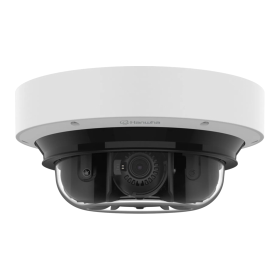
AT A GLANCE Appearance Components (Front Side) Item Description Item Description Lens 4 camera lenses show different directions. Dome cover Case cover used to protect the lens and the main unit. Illumination Sensor Detects incoming light to control the IR LED. Camera body Body part where the camera lens and connection terminals are included. - Page 10 overview Components (Rear Side) Item Description This port connects power and network via PoE+ injector. PoE+ port The button restores all camera settings to the factory default. Press and hold for about 5 seconds to reboot the system. If you reset the camera, the network settings will be adjusted so that DHCP can be Reset Button enabled.
-
Page 11: Installation & Connection
installation & connection INSTALLATION 2. Loosen the fastening screw on the camera body. You don’t have to completely remove the screws. This camera is waterproof and in compliance with the IP66 spec, but the jack connected to the external cable is not. You are recommended to install this product below the edge of eaves to prevent the cable from being externally exposed. - Page 12 installation & connection Inserting a Micro SD card Removing a Micro SD card Insert a Micro SD card in the arrow direction shown in the figure. Gently press down on the exposed end of the Micro SD card as shown in the diagram to eject the Micro SD card from the slot.
- Page 13 Installation (mount plate) 1-3. Take out the necessary cables from among the network and audio/alarm cables through the hole of the mount plate. [Directly installing on ceiling] 1-1. Place the mount plate on the desired location considering the direction to be monitored, mark the locations for the screw holes and cable holes, and then drill the holes.
- Page 14 installation & connection 2-3. Place the pipe on the mount plate. [Attaching to the unbundled adapter] 2-4. Fix the mount plate using appropriate screws. Choose and purchase a necessary one of the following options (unbundled) that is suitable to the installation site or for your convenience.
- Page 15 Installation (camera body and dome cover) 3. Pull out the cable bushing from the camera body, as shown in the figure. 1. Connect the safety wire to the mount plate. 2. Mount the camera body to the mount plate. Mount it to fit the hinges as shown in the image. [Installing the network cable] (IP66) Use a cable bushing compliant with the network cable to be connected.
- Page 16 installation & connection 6. Insert the cable bushing of the network cable into the camera body. [Installing audio/alarm cables] 8. Pull out the cable bushing from the camera body, as shown in the figure. 7. Connect the network cable jack to the PoE+ port of the camera. 16_ installation &...
- Page 17 9. Insert the cable bushing of the audio/alarm cable(separately sold) into the camera body. 11. Lift up the camera body and push the mounting clips until they click into place. 12. Using the fastening screws on the camera body, fix the camera body to the mount plate. 10.
- Page 18 installation & connection 13. Adjust the lens to the desired direction by referring to “Adjusting the monitoring direction for the Outdoor installation camera”. When you install it outside of the building, please waterproof it with waterproof butyl rubber tape (can be If you tilt the lens, you may need to adjust the lens as this may block the screen.
- Page 19 Adjusting the monitoring direction for the camera Installation precautions when using the IR mode ~ <Auto1>: Optimized for IR light to radiate evenly when the center of the object is saturated. ~ <Auto2>: Optimized for IR light to evenly radiate at the overall IR brightness. [Example of installing the ceiling mount] Front direction CH 3...
-
Page 20: Connecting With Other Device
installation & connection CONNECTING WITH OTHER DEVICE Powering and networking Connect the PoE+ device with the PoE+ port of the camera. WiFi dongle Connect and use a PoE+ -enabled router. Use a PoE+ device that complies with the IEEE 802.3at standard. Network Cable Specification Item Contents... - Page 21 ~ Audio in : Selectable (microphone/Line-in), Supported voltage: 2.5VDC (4mA), Input impedance: 2K Ohm ~ Audio out : Line-out (3.5mm mono jack), Maximum output: 1Vrms, Line out impedance : 600Ω The audio/alarm cable for PNM-C32083RVQ/PNM-C16083RVQ need to be purchased separately. English _21...
- Page 22 installation & connection Connecting to the I/O port box To connect to an external sensor Connect the Alarm I/O cable to the corresponding port of the port box. To use as an Alarm IN: Connect one of the [ALARM I/O] port and the other terminal to the [GND] port. Alarm In Wiring Diagram(example) Alarm cable External connection...
- Page 23 To connect to an alarm output If devices (e.g., flashing light and siren) that exceed the voltage and current specifications are connected by using the open collector method, it may cause damage. (12VDC, 20 mA MAX) Refer to the alarm out connection diagram below case. Alarm Out Wiring Diagram(example) Alarm cable External connection...
-
Page 24: Network Connection And Setup
network connection and setup You can set up the network settings according to your network configurations. CONNECTING THE CAMERA DIRECTLY TO A DHCP BASED DSL/CABLE MODEM CONNECTING THE CAMERA DIRECTLY TO LOCAL AREA NETWORKING Connecting to the camera from a local PC in the LAN INTERNET 1. -
Page 25: Using Device Manager
If using a Broadband Router ~ IP Address : Enter an address falling in the IP range provided by the Broadband Router. Device manager program can be downloaded from <Support>-<Online Tool> menu at Hanwha Vision website ex) 192.168.1.2~254, 192.168.0.2~254, (https://www.HanwhaVision.com). -
Page 26: Manually Registering Camera
network connection and setup Configuring Dynamic IP AUTOMATICALLY CONFIGURING IP Receive IP address from DHCP 1. Click the camera from the list that you want to automatically ~ Example of the Dynamic IP environment configure the IP. PNM-C16083RVQ - If a Broadband Router, with cameras connected, is assigned an IP address by the DHCP server 2. -
Page 27: Port Range Forward (Port Mapping) Setup
PORT RANGE FORWARD (PORT MAPPING) SETUP Setting up Port Range Forward for several network cameras ~ You can set a rule of Port Forwarding on the Broadband Router device through its configuration web page. If you have installed a Broadband Router with a camera connected, you must set the port range forwarding on the ~ A user can change each port using the camera setting screen. -
Page 28: Connecting To The Camera From A Shared Local Pc
network connection and setup CONNECTING TO THE CAMERA FROM A SHARED LOCAL PC 1. Run device manager. It will scan for connected cameras and display them as a list. 2. Double-click a camera to access. The Internet browser starts and connects to the camera. Access to the camera can also be gained by typing the camera’s IP address in the address bar of the Internet browser. -
Page 29: Connecting To The Camera
web viewer CONNECTING TO THE CAMERA Connecting via Bonjour 1. Run the client or operating system in support of the Bonjour protocol. Normally, you would 2. Click the camera name for search. In the Mac operating system, click the camera name searched from the Bonjour tab of Safari. 1. -
Page 30: Password Setting
web viewer PASSWORD SETTING CAMERA WEB VIEWER SETUP When you access the product for the first time, you must register the 1. Click the [Setup ( )] icon. login password. 2. The Settings window appears. 3. You can configure settings for the camera’s basic information, video, audio, network, event, analysis, and For a new password with 8 to 9 characters, you must use at least 3 system over the network. -
Page 31: Troubleshooting
appendix TROUBLESHOOTING PROBLEM SOLUTION No signal is found at the Alarm Output PROBLEM SOLUTION port even when an intelligent video ~ Check alarm output port settings. analysis event is generated. ~ On the authentication popup window prompted when initially accessing https, click "View Authentication Certificate"... - Page 32 Operation of this equipment in a residential area is likely to cause harmful interference in which case the user will be required to correct the interference at his own expense. Hanwha Vision cares for the environment at all product manufacturing stages, and is taking measures to provide customers with more environmentally friendly products.
Need help?
Do you have a question about the PNM-C32083RVQ and is the answer not in the manual?
Questions and answers