Advertisement
DESCRIPTION
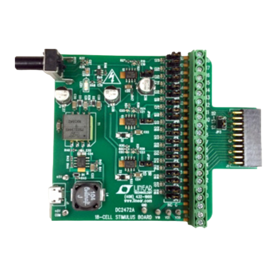
Demonstration circuit 2472A is a USB-powered resistor-
string, voltage ladder with variable output. The DC2472A
provides a simple battery stack simulator for connection
directly to most of Linear Technology's LTC68xx "battery
stack monitor" demo boards.
Using the 5V from a USB charger, the DC2472 generates
an isolated high voltage from ~25V to ~75V, applied to
a resistor string generating 18 voltages taps. These taps
provide a simulation of a string of series connected bat-
tery cells, each tap pair providing nominally the same
virtual cell voltage. The input voltage to the resistor string
is adjustable by an on-board potentiometer to furnish a
divided output voltage in a range of about 1.5V-4.2V per
cell to demonstrate operation at conditions comparable
to a wide range of cell chemistries.
CONNECTION TO AN LTC68XX DEMO-BOARD
1. The back side of the DC2472A shows where the
LTC68xx demo board connectors should be attached.
Simply line up the finger contacts with the associated
screw terminal connector according to whether the
connector is a 16- or 19-contact model. The screws
for securing the connections should be facing the com-
ponent side of the DC2472A. Torque the 16- or 19-posi-
tion connections to 0.2-0.25Nm. A 22-contact adapter
Typical 12-Cell Demo
Arrow.com.
Downloaded from
DEMO MANUAL DC2472A
18-CELL STIMULUS BOARD
(e.g. DC2701A) should be torqued to 0.22-0.25Nm.
See Figure 1 for example installations.
2. In the case of a 15-cell demo (e.g. for LTC6812), the
pinout requires every sixth tap pair to be shorted over.
To accomplish this, place JP19, JP20, and JP21 to the
"15" position. In all other usages, leave those jumpers
in the '18' position. Note that cell voltages will increase
20% with placement of jumpers in the "15" position
due to the reduced division factor.
3. A USB to USB MICRO-B cable (like non-Apple cell
phone charger) provides a simple means of powering
the DC2472A from a 1A USB charger (some computer
ports may not provide adequate current for stable
output levels). Alternatively, a 5V bench power supply
can be connected to the power input turrets (+5V &
+5V COM) with clip-leads. Note that the +5V connec-
tions are isolated with respect to the GND turret of the
DC2472A, so the +5V COM and GND cannot be used
interchangeably.
WARNING – THIS BOARD GENERATES VOLTAGE POTEN-
TIALS UP TO 80V
Design files for this circuit board are available at
http://www.linear.com/demo/DC2472A
L, LT, LTC, LTM, Linear Technology and the Linear logo are registered trademarks of Analog
Devices, Inc. All other trademarks are the property of their respective owners.
Typical 15- or 18-Cell Demo
Figure 1. Output Connection Options
Typical DC2701 Adapter Usage
dc2472af
1
Advertisement
Table of Contents

Related Manuals for Analog Devices Linear Technology DC2472A


Summary of Contents for Analog Devices Linear Technology DC2472A
- Page 1 DEMO MANUAL DC2472A 18-CELL STIMULUS BOARD DESCRIPTION Demonstration circuit 2472A is a USB-powered resistor- (e.g. DC2701A) should be torqued to 0.22-0.25Nm. string, voltage ladder with variable output. The DC2472A See Figure 1 for example installations. provides a simple battery stack simulator for connection 2.
- Page 2 DEMO MANUAL DC2472A QUICK START PROCEDURE 1. Power up the DC2472A from the USB cable or bench 4. Operate the LTC68xx demo as applicable. Note that supply. resistor-string battery simulations (and DC2472A in particular) cannot generally generate currents suitable 2. Once powered, the Blue LED1 should illuminate. for properly demonstrating cell-balancing activity.
- Page 3 DEMO MANUAL DC2472A THEORY OF OPERATION The DC2472A is a resistor-string voltage-divider ladder by the demo board that is being powered. The amplifier powered by a variable voltage. A block diagram is shown is decoupled and stabilized to operate with the capacitive in Figure 3 and shows the key functional elements.
- Page 4 DEMO MANUAL DC2472A DEMONSTRATION BOARD IMPORTANT NOTICE Linear Technology Corporation (LTC) provides the enclosed product(s) under the following AS IS conditions: This demonstration board (DEMO BOARD) kit being sold or provided by Linear Technology is intended for use for ENGINEERING DEVELOPMENT OR EVALUATION PURPOSES ONLY and is not provided by LTC for commercial use.
Need help?
Do you have a question about the Linear Technology DC2472A and is the answer not in the manual?
Questions and answers