Advertisement
Quick Links
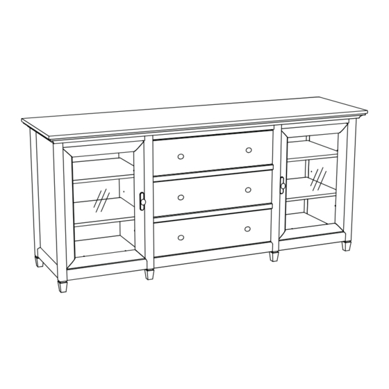
415321
Credenza
Edge Water Collection
PLEASE CONTACT US
BEFORE RETURNING
YOUR UNIT TO THE STORE
1-800-523-3987
www.sauder.com
NOTE: THIS INSTRUCTION BOOKLET CONTAINS
IMPORTANT SAFETY INFORMATION.
PLEASE READ AND KEEP FOR FUTURE REFERENCE.
English .................... Page 1-28
Français ...............Pages 29-32
Made in the USA
Espanol .............Páginas 33-36
Archbold, OH
Lot #: 353834
Date Purchased: ____________________
07 / 19 / 13
Advertisement

Related Manuals for Sauder Edge Water Credenza 415321


Summary of Contents for Sauder Edge Water Credenza 415321
- Page 1 PLEASE READ AND KEEP FOR FUTURE REFERENCE. BEFORE RETURNING English ....Page 1-28 YOUR UNIT TO THE STORE Français ....Pages 29-32 Made in the USA 1-800-523-3987 Espanol .....Páginas 33-36 Archbold, OH www.sauder.com Lot #: 353834 07 / 19 / 13 Date Purchased: ____________________...
-
Page 2: Table Of Contents
• Check the size and weight of your TV. Compare it to the diagram below – before you begin assembly! • This Sauder unit is designed for use with televisions weighing less than 95 pounds. Never use with a TV that weighs more. -
Page 3: Part Identification
RIGHT MOLDING DRAWER LEFT SIDE ADJUSTABLE SHELF LEFT MOLDING D174 DRAWER BACK FRONT LEG BRACE MOLDING D983 DRAWER BOTTOM BACK LEG DOOR GLASS VALANCE DOOR PANEL BOTTOM DOOR VALANCE FEET RIGHT BOTTOM SKIRT DRAWER BRACE D174 D983 415321 www.sauder.com/services Page 3... -
Page 4: Hardware Identification
46M CLIP - 16 BACKPLATE - 2 WARNING LABEL - 1 3M ANTI-SKID PAD - 1 (Refer to the step 22 for proper location and application) NAIL - 44 METAL PIN - 28 RUBBER SLEEVE - 16 Page 4 www.sauder.com/services 415321... - Page 5 BLACK 1-5/8" PAN HEAD SCREW - 6 BLACK 7/8" MACHINE SCREW - 6 BLACK 1-9/16" FLAT HEAD SCREW - 15 BLACK 9/16" PAN HEAD SCREW - 16 Screws are shown actual size. You may receive extra hardware with your unit. 415321 www.sauder.com/services Page 5...
-
Page 6: Assembly Steps
Look for this icon. It means a video assembly tip is available at: www.sauder.com/services/tips Do not insert CAM DOWELS Do not tighten the HIDDEN CAMS in this step. into these edges. Arrow Arrow Do not insert CAM DOWELS into these edges. - Page 7 Turn eleven CAM SCREWS (8F) into the FRONT LEGS (N) and DRAWER FRONTS (U). 415321 www.sauder.com/services Page 7...
- Page 8 Use your hammer to tap the MOLDING CONNECTOR (17F) into the notches in the MOLDINGS. Flat end Flat end Tap two MOLDING CONNECTORS (17F) into the notches in the MOLDINGS (V, W, and X). Page 8 www.sauder.com/services 415321...
- Page 9 Rounded edge BROWN 1-1/2" FLAT HEAD SCREW (9 used in this step) Rounded edge Rounded edge Fasten the MOLDINGS (V, W, and X) to the TOP (E). Use nine BROWN 1-1/2" FLAT HEAD SCREWS (14S). 415321 www.sauder.com/services Page 9...
- Page 10 GOLD 5/16" FLAT HEAD SCREW (12 used in this step) Fasten the CABINET RIGHTS (40CA) and CABINET LEFTS (40CB) to the UPRIGHTS (C and D). Use twelve GOLD 5/16" FLAT HEAD SCREWS (3S) through holes #1 and #4. Page 10 www.sauder.com/services 415321...
- Page 11 Fasten the FRONT LEGS (N) to the ENDS ( A and B) and UPRIGHTS (C and D). Tighen eight HIDDEN CAMS. Fasten the FEET (BB) to the LEGS (N). Use four BLACK 1-5/8" PAN HEAD SCREWS (27S). 415321 www.sauder.com/services Page 11...
- Page 12 Fasten the SIDE SKIRTS (T) to the ENDS (A and B). Use four BLACK 1-1/8" PAN HEAD SCREWS (9S). Fasten the BACK LEGS (O) to the ENDS (A and B). Use four BLACK 2-1/4" FLAT HEAD SCREWS(26S). Fasten two FEET (BB) to the BACK LEGS (O). Use two BLACK 1-5/8" PAN HEAD SCREWS (27S). Page 12 www.sauder.com/services 415321...
- Page 13 Tighten Arrow Risk of damage or injury. Hidden Cams must be completely Arrow Maximum tightened. Hidden 210 degrees Cams that are not completely tightened Minimum may loosen, and parts 190 degrees may separate. To completely tighten: 415321 www.sauder.com/services Page 13...
- Page 14 Fasten the LEFT BOTTOM (H) to the LEFT END (B) and LEFT UPRIGHT (D). Tighten four HIDDEN CAMS. Insert four METAL PINS (1R) into the TOP (E). Push the BACKS (J) onto the METAL PINS. Insert four METAL PINS (1R) into the holes in the top edges of the BACKS (J). Page 14 www.sauder.com/services 415321...
- Page 15 Maximum Arrow 210 degrees Minimum 190 degrees Fasten the BOTTOM (F) to the LEFT UPRIGHT (D). Tighten two HIDDEN CAMS. NOTE: Be sure the METAL PINS insert into the holes in the BOTTOM. 415321 www.sauder.com/services Page 15...
- Page 16 Fasten the BRACE (K) to the LEFT UPRIGHT (D). Tighten the HIDDEN CAM. NOTE: Be sure the PIN in the BRACE inserts into the hole in the LEFT UPRIGHT (D). Repeat this step using the remaining BRACE MOLDING (Y) and BRACE (K). *U.S. Patent No. 5,499,886 Page 16 www.sauder.com/services 415321...
- Page 17 Fasten the RIGHT UPRIGHT (C) to the TOP (E), BOTTOM (F), and BRACES (K). Tighten six HIDDEN CAMS. NOTE: Be sure the PINS in the BRACES insert into the holes in the RIGHT UPRIGHT. Fasten the RIGHT END (A) to the RIGHT MOLDING (W). Tighten two HIDDEN CAMS. 415321 www.sauder.com/services Page 17...
- Page 18 Fasten the RIGHT BOTTOM (G) to the RIGHT END (A) and RIGHT UPRIGHT (C). Tighten four HIDDEN CAMS. Fasten the DOOR VALANCES (Q) and VALANCE (P) to the FRONT MOLDING (V). Use seven BROWN 1-1/2" FLAT HEAD SCREWS (14S). Page 18 www.sauder.com/services 415321...
- Page 19 Fasten the DOOR SKIRTS (S) to the RIGHT and LEFT BOTTOMS (G and H). Use four BLACK 9/16" LARGE HEAD SCREWS (1S). Fasten the SKIRT (R) to the BOTTOM (F). Use three BLACK 9/16" LARGE HEAD SCREWS (1S). 415321 www.sauder.com/services Page 19...
- Page 20 Make equal margins along all four edges of the BACKS (I). Push on opposite corners of your unit if needed to make it “square”. Fasten the BACKS (I) to your unit using the NAILS (1N). NOTE: Perforations have been provided for access through the BACK. Carefully cut out the holes needed. Page 20 www.sauder.com/services 415321...
- Page 21 Glass Doors Shown above, you have the choice to fasten GLASS DOORS or PANELED DOORS to your unit. In the next step, you may fasten a DOOR GLASS (Z) or DOOR PANEL (AA) to your DOORS (L). 415321 www.sauder.com/services Page 21...
- Page 22 Fasten four HINGES (14H) to the DOORS (L). Use eight BLACK 1/2" FLAT HEAD SCREWS (11S) Fasten eight CLIPS (46M) to the DOORS (L). Lay a DOOR GLASS (Z) or a DOOR PANEL(AA) inside the frame of the DOORS (L) and turn the CLIPS to secure them. Page 22 www.sauder.com/services 415321...
- Page 23 Fasten a BACK PLATE (18K) and KNOB (17K) to the DOOR (L). Use a BLACK 1-1/8" MACHINE SCREW (21S). Push a DOOR STOP (4I) into the hole in the RIGHT BOTTOM (G). Repeat this step for the other DOOR (L) and DOOR STOP (4I) to the left side of your unit. 415321 www.sauder.com/services Page 23...
- Page 24 Tighten the screws after making adjustments. To adjust the DOORS in or out (depth), loosen the mounting screw one turn and move the DOORS in or out, as needed. Tighten the mounting screw after making adjustments. Page 24 www.sauder.com/services 415321...
- Page 25 (D10 and D11) and DRAWER BRACE (CC). Use five BLACK 1-9/16" FLAT HEAD SCREWS. Fasten a DRAWER BRACE (CC) to the DRAWER FRONT (U). Tighten one HIDDEN CAM. Repeat step 20 for the remaining drawer parts. 415321 www.sauder.com/services Page 25...
- Page 26 NOTE: The screw head in the CAM must be visible through the slotted hole in the SLIDE. Fasten two KNOBS (17K) to the DRAWER FRONT (U). Use two BLACK 7/8" MACHINE SCREWS (37S). Repeat this step for the other drawers. Page 26 www.sauder.com/services 415321...
- Page 27 TV is in place, it should hide the label. Peel off the backing and apply the label as shown in the diagram. NOTE: This is a permanent label intended to last for the life of the product. Once applied, do not try to remove it. 415321 www.sauder.com/services Page 27...
- Page 28 Tighten the SCREW when finished with adjustments. NOTE: Please read the back pages of the instruction booklet for important safety information. This completes assembly. To clean your unit, dampen a cloth with tap water and wipe. Page 28 www.sauder.com/services 415321...
-
Page 29: Français
PLINTHE ............1 pour future référence. VIS TÊTE LARGE 14 mm NOIRE ....14 PLINTHE DE PORTE ........2 Pour contacter Sauder VIS TÊTE PLATE 8 mm DORÉE ....24 PLINTHE LATÉRALE ........2 en ce qui concerne cet VIS TÊTE GOUTTE DE SUIF 28 mm NOIRE 4 DEVANT DE TIROIR ........ - Page 30 • Vérifi er la taille et le poids du téléviseur. Le comparer au dans les crans des MOULURES (V, W et X). diagramme ci-dessous avant de commencer l'assemblage ! • Cette unité Sauder est conçue pour les téléviseurs pesant moins de 43 kg. Ne jamais utiliser avec des ÉTAPE 4 téléviseurs plus lourds.
- Page 31 Comme illustré ci-dessus, il est possible de fi xer des PORTES EN VERRE ou des PORTES À PANNEAU à l’unité. À l’étape suivante, il est possible de fi xer un VERRE DE PORTE (Z) ou un PANNEAU DE PORTE (AA) aux PORTES (L). 415321 www.sauder.com/services Page 31...
- Page 32 Serrer un EXCENTRIQUE ESCAMOTABLE. 4 Fixer l'ARRIÈRE DE TIROIR (D174) aux CÔTÉS DE TIROIR (D10 et D11) et l’ENTRETOISE DE TIROIR (CC). Utiliser cinq VIS TÊTE PLATE 40 mm NOIRES. Répéter l'étape 20 pour les autres pièces du tiroir. Page 32 www.sauder.com/services 415321...
-
Page 33: Espanol
13 mm ............8 en contacto con MOLDURA DERECHA ........1 TORNILLO MARRÓN DE CABEZA PERDIDA Sauder en cuanto a de 38 mm ............. 16 MOLDURA IZQUIERDA ......... 1 esta unidad, refi érase TORNILLO NEGRO PARA METAL de 28 mm ...2 MOLDURA DE RIOSTRA ....... - Page 34 - antes de comenzar el ensamblaje! dentro de las muescas de las MOLDURAS (V, W y X). • Esta unidad Sauder está diseñada para ser usada con televisores cuyo peso sea inferior a 43 Kg. Nunca la use PASO 4 para un televisor de mayor peso.
- Page 35 Expuesto arriba, tiene la opción de ajustar VIDRIO DE LAS PUERTAS o PANELES DE LAS PUERTAS a su unidad. En el siguiente paso, es posible ajustar un VIDRIO DE LA PUERTA (Z) o PANEL DE LA PUERTA (AA) a sus PUERTAS (L). 415321 www.sauder.com/services Page 35...
- Page 36 4 Fije un DORSO DE CAJÓN (D174) a los LADOS DE CAJÓN (D10 y D11) y a la RIOSTRA DE CAJÓN (CC). Utilice cinco TORNILLOS NEGROS DE CABEZA PERDIDA de 40 mm. Repita el paso 20 para las piezas restantes del cajón. Page 36 www.sauder.com/services 415321...
-
Page 37: Safety
équipé. • Blessure physique. Le mobilier peut être mobilier. très lourd. • Ne pas pousser le mobilier, surtout sur la moquette. Se faire aider par une autre personne pour soulever l’élément et le mettre en place. 415321 www.sauder.com/services Page 37... - Page 38 • Lesión física. El mobiliario puede ser • No empuje la unidad, especialmente muy pesado. sobre un piso alfombrado. Pide la ayuda de otra persona en levantar la unidad y colocarla en lugar. Page 38 www.sauder.com/services 415321...
-
Page 39: Warranty
4. La présente garantie ne s’applique qu’aux défauts garantis qui se produisent des composantes de mobilier Sauder. Le mot « défaut », tel qu’il est utilisé sous pour la première fois et qui sont signalés à Sauder dans les limites de ouverture les termes de la présente garantie, comprend les imperfections des pièces qui... - Page 40 Archbold, Ohio, where it all began. Certifi cate of Conformity The Sauder name on the box ensures that 1. This certifi cate applies to the Sauder Woodworking Product identifi ed by this Instruction Book. the item you have purchased is made with 2.
Need help?
Do you have a question about the Edge Water Credenza 415321 and is the answer not in the manual?
Questions and answers