Advertisement
Quick Links
sauder.com
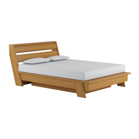
Queen Platform Bed
Soft Modern Collection | 415138
Need help? Visit Sauder.com to view video assembly tips or chat with a live rep.
Prefer the phone? Call 1-800-523-3987.
Share your journey!
You are getting sleepy.
Very sleepy.
NOTE: THIS INSTRUCTION
BOOKLET CONTAINS IMPORTANT
SAFETY INFORMATION.
PLEASE READ AND KEEP FOR
FUTURE REFERENCE.
English pg 1-22
Français pg 23-26
Español pg 27-30
Lot # 357958
12/03/13
Purchased: __________________
Be sure to give us a ring before
making any returns. 1-800-523-3987
Advertisement

Related Manuals for Sauder Soft Modern 415138


Summary of Contents for Sauder Soft Modern 415138
- Page 1 Soft Modern Collection | 415138 NOTE: THIS INSTRUCTION BOOKLET CONTAINS IMPORTANT SAFETY INFORMATION. Need help? Visit Sauder.com to view video assembly tips or chat with a live rep. PLEASE READ AND KEEP FOR FUTURE REFERENCE. Prefer the phone? Call 1-800-523-3987.
- Page 2 SHORT SUPPORT (2) HEADBOARD SLAT SUPPORT (4) OUTER SUPPORT (2) RIGHT LEG (1) SUPPORT BRACE (4) LEFT LEG (1) SHORT CLEAT (4) RIGHT RAIL (1) LONG CLEAT (2) LEFT RAIL (1) HEADBOARD BRACE (1) FOOT RAIL (1) Page 2 415138 www.sauder.com/services...
- Page 3 Part Identifi cation www.sauder.com/services 415138 Page 3...
-
Page 4: Table Of Contents
BLACK 1-15/16" FLAT HEAD SCREW - 32 12S BROWN 1" FLAT HEAD SCREW - 4 BLACK 1-1/4" FLAT HEAD SCREW - 24 102S 103S SILVER 1" LARGE HEAD SCREW - 19 BLACK 2-3/8" FLAT HEAD BOLT - 8 Page 4 415138 www.sauder.com/services... - Page 5 Step 1 Look for this icon. It means a video assembly tip is available at www.sauder.com/services/tips Assemble your unit on a carpeted fl oor or on the empty carton to avoid scratching your unit or the fl oor. å NOTE: You will need someone’s help to build this unit. Due to the size and weight of this unit, you should build it close to its å...
- Page 6 Step 2 Turn thirteen CAM SCREWS (8F) into the å RAILS (J2 and K2) and FOOT PLATFORM (O2). Page 6 415138 www.sauder.com/services...
- Page 7 SUPPORTS (G2) and FOOT RAIL (L2) as shown in the lower diagram. Use ten BLACK 9/16" LARGE HEAD SCREWS (1S). (8 used) Surface with HIDDEN CAMS BLACK 9/16" LARGE HEAD SCREW (10 used in this step) www.sauder.com/services 415138 Page 7...
- Page 8 Step Step 4 Fasten the PLATFORMS (M2 and N2) to the FOOT å PLATFORM (O2). Tighten four HIDDEN CAMS. Rounded edge Rounded edge Rounded edge Page 8 415138 www.sauder.com/services...
-
Page 9: Hidden Cam
Tighten Risk of damage or Arrow injury. HIDDEN CAMS must be completely Arrow Maximum tightened. HIDDEN 210 degrees CAMS that are not completely tightened may loosen, and parts may separate. To Minimum completely tighten: 190 degrees www.sauder.com/services 415138 Page 9... - Page 10 Step Step 6 Fasten the RAILS (J2, K2, and L2) to the å PLATFORMS (M2, N2, and O2). Tighten seventeen HIDDEN CAMS. Maximum Arrow 210 degrees Minimum 190 degrees Page 10 415138 www.sauder.com/services...
-
Page 11: Silver 1" Large Head Screw
Step Step 7 Fasten the PLATFORM DECKS (P2) to the å PLATFORMS (M2, N2, and O2). Use nineteen SILVER 1" LARGE HEAD SCREWS (102S). 102S SILVER 1" LARGE HEAD SCREW (19 used in this step) 102S www.sauder.com/services 415138 Page 11... -
Page 12: Black 1-15/16" Flat Head Screw
(4 used in this step) Surface with Unfi nished edge two holes This hole must be here. 103S BLACK 2-3/8" FLAT HEAD BOLT (4 used in this step) BLACK 1-15/16" FLAT HEAD SCREW (4 used in this step) Page 12 415138 www.sauder.com/services... - Page 13 Use twelve BLACK 1-1/4" FLAT HEAD SCREWS (7S). Fasten the LONG CLEATS (V) to the RAILS (D2 and L2). Use å eight BLACK 1-1/4" FLAT HEAD SCREWS (7S). BLACK 1-1/4" FLAT HEAD SCREW (20 used in this step) www.sauder.com/services 415138 Page 13...
- Page 14 Fasten the HEADBOARD TOP (C2) to the HEADBOARD å TOP SUPPORT (F2). Tighten three HIDDEN CAMS. Finished edge S u r f a c i t h H I D D E N Flat edge Maximum Arrow 210 degrees Minimum 190 degrees Page 14 415138 www.sauder.com/services...
- Page 15 S u r f a c i t h H I D D E N S u r f a c i t h H I D D E N Maximum Arrow 210 degrees Minimum 190 degrees www.sauder.com/services 415138 Page 15...
- Page 16 Step 12 Fasten the HEADBOARD TOP (C2) and HEADBOARD å TOP SUPPORT (F2) to the HEADBOARD RIGHT END (A2). Tighten three HIDDEN CAMS. Angled edge Flat edge Page 16 415138 www.sauder.com/services...
- Page 17 HEADBOARD RIGHT END. NOTE: Be sure the METAL PINS in the HEADBOARD RIGHT å END insert into the holes in the HEADBOARD SLATS (E2). (8 used) BLACK 9/16" LARGE HEAD SCREW (4 used in this step) www.sauder.com/services 415138 Page 17...
- Page 18 BRACE (W) to the HEADBOARD LEFT END (B2). Tighten fi ve HIDDEN CAMS. BLACK 9/16" LARGE HEAD SCREW (4 used in this step) Angled edge Unfi nished edge Maximum Arrow 210 degrees (8 used) Minimum 190 degrees Page 18 415138 www.sauder.com/services...
- Page 19 Fasten the HEADBOARD BRACE (W) to the å HEADBOARD RAIL (D2). Use four BROWN 1" FLAT HEAD SCREWS (12S). 103S 103S BROWN 1" FLAT HEAD SCREW (4 used in this step) BLACK 2-3/8" FLAT HEAD BOLT (4 used in this step) www.sauder.com/services 415138 Page 19...
- Page 20 fi nal on edge location for less movement or relocation. 64 1/2" minimum 15 inches The platform in Step 17 should be built in this location. See Step 18 for helpful information. Page 20 415138 www.sauder.com/services...
- Page 21 U n fi u r f a i s h e F i n F i n i s h r f a BLACK 1-15/16" FLAT HEAD SCREW (28 used for the HEADBOARD RAILS) www.sauder.com/services 415138 Page 21...
- Page 22 To cover screws on the HEADBOARD ENDS and LEGS. (8 used) Use the locator holes closest to the headboard for placement of the bed over the support. 29 inches 13 inches Support (11 used) To cover HIDDEN CAMS Support Page 22 415138 www.sauder.com/services...
- Page 23 EXTRÉMITÉ DROITE DE TÊTE DE LIT ..1 EXCENTRIQUE ESCAMOTABLE ....50 Pour contacter Sauder EXTRÉMITÉ GAUCHE DE TÊTE DE LIT ..1 CHEVILLE D'EXCENTRIQUE ......37 en ce qui concerne cet DESSUS DE TÊTE DE LIT ........1 VIS D'EXCENTRIQUE ..........
- Page 24 Fixer dix CONSOLES EN MÉTAL (4G) sur les SUPPORTS DE LATTES DE TÊTE DE LIT (G2) et la TRAVERSE DE PIED (L2) comme l’indique le schéma inférieur. Utiliser dix VIS TÊTE LARGE 14 mm NOIRES (1S). Page 24 415138 www.sauder.com/services...
- Page 25 Fixer les TASSEAUX COURTS (U2) sur les TRAVERSES (J2 et K2). Utiliser douze VIS TÊTE PLATE 32 mm NOIRES (7S). Fixer les TASSEAUX LONGS (V) sur les TRAVERSES (D2 et L2). Utiliser huit VIS TÊTE PLATE 32 mm NOIRES (7S). www.sauder.com/services 415138 Page 25...
- Page 26 SUPPORT CENTRAL. Ceci assurer un TÊTE DE LIT (D2). Utiliser quatre VIS TÊTE support adéquat du lit. PLATE 25 mm MARRON (12S). Ceci complète l'assemblage. Nettoyer à l’ a ide d’une encaustique pour meubles ou d’un chiff on humide. Essuyer. Page 26 415138 www.sauder.com/services...
- Page 27 EXTREMO IZQUIERDO DE LA CABECERA ..1 PASADOR DE EXCÉNTRICO ........37 Pour contacter Sauder PANEL SUPERIOR DE CABECERA ......1 BIELA DE EXCÉNTRICO ..........13 en ce qui concerne cet RIEL DE LA CABECERA ............. 1 SOPORTE DE METAL ............10...
- Page 28 Fije los diez SOPORTES DE METAL (4G) a los SOPORTES DE LOS LISTONES DE LA CABECERA (G2) y al RIEL DE LAS PATAS (L2), como se muestra en el diagrama inferior. Utilice diez TORNILLOS NEGROS DE CABEZA GRANDE de 14 mm (1S). Page 28 415138 www.sauder.com/services...
- Page 29 Fije las AGARRADERAS CORTAS (U2) a los RIELES (J2 y K2). Utilice doce TORNILLOS NEGROS DE CABEZA PERDIDA de 32 mm (7S). Fije las AGARRADERAS LARGAS (V) a los RIELES (D2 y L2). Utilice ocho TORNILLOS NEGROS DE CABEZA PERDIDA de 32 mm (7S). www.sauder.com/services 415138 Page 29...
- Page 30 CENTRAL. Esto asegura que la cama tenga el soporte apropiado. CABECERA (D2). Utilice cuatro TORNILLOS MARRONES DE Esto completa el ensamblaje. Limpie con su pulimento para CABEZA PERDIDA de 25 mm (12S). muebles preferido o un paño húmedo. Seque con un paño. Page 30 415138 www.sauder.com/services...
- Page 31 GARANTIE LIMITÉE DE 5 ANS 1. Sauder Woodworking Co. (Sauder®) off re une couverture de garantie limitée à l’ a cheteur 4. La présente garantie ne s’ a pplique qu’ a ux défauts garantis qui se produisent pour initial du présent produit pendant une période de cinq ans à...
- Page 32 Dear Valued Customer: So, how did it go? Thanks so much for choosing Sauder® furniture. I hope the Set a world record for speed? purchase and assembly process was a positive experience Feeling good about yourself? and you feel good about the furniture you just built. If you Nice.
Need help?
Do you have a question about the Soft Modern 415138 and is the answer not in the manual?
Questions and answers