
Subscribe to Our Youtube Channel
Related Manuals for Girard Systems GC274B


Summary of Contents for Girard Systems GC274B
- Page 1 AC MOTOR CONTROL MODULE GC274B INSTALLATION and PAIRING INSTRUCTIONS REV.12302015 RV AWNING PRODUCTS 1361 CALLE AVANZADO, SAN CLEMENTE, CA 92673 (800) 382-8442 FAX (949)276-5500 www.girardrv.com...
- Page 2 Shore Power – if connected; Generator Power – if the generator is running; Inverter Power – batteries must be charged for inverter operation. Girard Systems awnings are supplied with an electric motor appropriate to the product. Page 2 of 11...
-
Page 3: Table Of Contents
These components must be electronically matched, programmed or paired before use. This is usually done at the Girard Systems factory. Should the need arise for the user to pair a device with the motor controller they must refer to the appropriate manual for the devices applicable to their particular installation. -
Page 4: Product Description
100ft in the presence of obstructions. The RF transmission frequency is 433.92MHZ. • The GC274B may be programmed with up to 20 compatible remote modules. If an additional module is programmed it will replace the most recently programmed module. The previous 19 modules will remain unchanged. -
Page 5: Specification
1. Install a UL approved 110VAC junction box in which to make the electrical connections. 2. Route the Awning’s Motor cable to this location and make the connections to the GC274B in accordance with NEC requirements. Mount the GC274B on the wall using the screws and tape provided. Page 5 of 11... -
Page 6: Wiring Diagram
Page 6 of 11... -
Page 7: Setup And Programming
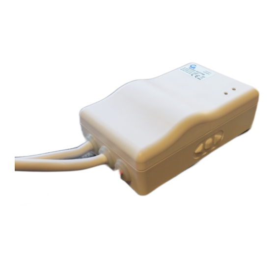
2. Programming the GC274B to a Remote handset or Wall switch a. Supply power to the GC274B b. Press and hold the MIDDLE and RIGHT buttons on the GC274B (Fig 3) for about 5 seconds until the Green LED starts to flash. -
Page 8: Cancel A Remote Controller
3. Cancel one Remote from the GC274B a. Supply power to the GC274B b. Press and hold the MIDDLE and RIGHT buttons on the GC274B (Fig 3) for about 3 seconds until the Green LED starts to flash. c. Press STOP (Fig. 1): The Green LED will stop blinking and remain illuminated. -
Page 9: Programming To A Motion Sensor
6. Programming the GC274B to a Motion Sensor (98GC779G) This procedure will require opening up the motion sensor module by following the directions below; a. Remove the 2 small cross head screws which secure the motion sensor to the mounting bracket. - Page 10 c. Remove the 4 cross head screws holding the module together. Remove the base plate and silicone insert. See Fig.3. Magnet Base plate Silicone Insert Fig.3 d. Turn the base plate over (Magnet down). Then place the motion sensor on top of it so that the magnet is aligned with the reed switch.
- Page 11 Ensure that the magnet and reed switch are aligned and verify the electrical connection before proceeding. d. Press and hold the MIDDLE and RIGHT buttons on the GC274B (Fig 2) for about 3 seconds until the Green LED starts to flash.
Need help?
Do you have a question about the GC274B and is the answer not in the manual?
Questions and answers
I have two gc274B control modules plugged into the same AC outlet. One has the red light on and the other does not. Do I need to replace the Controller?
Good Afternoon I have 2 Girard Awning controllers GC274 B mounted in the besement of my 2022 Newmar. the two small flat plastic mounting slide plates screwed to the wall have cracked/broken. Would it be possible for you to kindly send me two new ones?