
Related Manuals for Tractel HF 32/1/B


Summary of Contents for Tractel HF 32/1/B
- Page 1 HF 32/1/B Universal load cell Operating equipment in maintenance accordance with CE directives manual MS 32/1/B R 03/03...
-
Page 2: General Warning
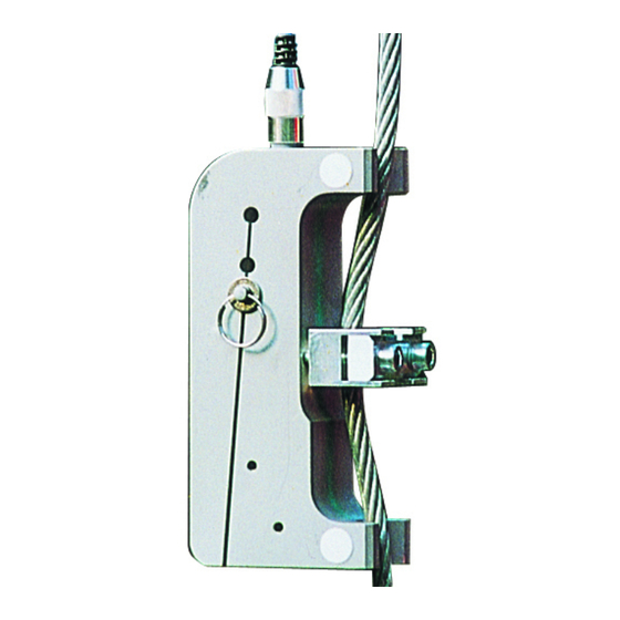
4- Never apply to the Dynasafe a load or an effort in excess of the working load limit, and never use it for an operation for which it is not intended. 5- TRACTEL S.A.S declines any responsibility for the consequences of dismantling or altering the machine by any unauthorized person. - Page 3 INSTALLATION OF HF 32/1/B LOAD CELL Fig. 1 Components of the load cell A- 2 m connecting cable F- Tare screw. K-Tightening bracket. B- Flat washer. G- Locking nut. L-Rubber compression pad. C- Adjusting pin. H-Traction part. M-Wire rope. D- Locking ring.
- Page 4 INSTALLATION OF HF 32/1/B LOAD CELL Positioning the adjusting pin as a function of the effort in the wire rope For wire rope from 5 mm to 8 mm diameter and for loads ranging from 50 kg to 900 kg.
- Page 5 INSTALLATION OF HF 32/1/B LOAD CELL Correct positioning of the tightening bracket depending on the diameter of the wire rope. 5 mm to 8mm wire rope without rubber compression pad, M6 screws * 30 mm(supplied) M6 screw * 30 mm (x2)
- Page 6 OPERATION AND ADJUSTMENT OF HF 85 LOAD CELL WIRING FROM LOAD CELL ALARMS HIGH SPEED LIFTING CONTACT EFF.DYN. DEPH POWER SUPPLY LOW SPEED LIFTING CONTACT ELECTRICAL CONTROL BOX Fig. 4 The switch is 25 mA 24V AC or 2 mA 15 V DC. It is therefore necessary to check the interface compatibility if HF 85 is not used.
- Page 7 INSTALLATION AND ADJUSTMENT OF HF 32 AND HF 85 Contactors Load cell Alarms TEST EFF. DEPH Vac Supply Auxiliary Contactors contact Fig. 5 Test function Once the load cell has been fitted and the various connections have been made to the monitor, there is a test procedure to check the correct operation for the installation.
- Page 8 OPERATION AND ADJUSTMENT HF 32 AND HF 85 Adjustment of the safety trip point Essential conditions : - The load cell must be correctly installed and wired. - The hook of the lifting system should be free of any load. - A successfull operating test Equipment required : - A load (“Pm”) equivalent to 100 % of the working load limit...
- Page 9 NOTES : MS 32/1/B R 03/03...
Need help?
Do you have a question about the HF 32/1/B and is the answer not in the manual?
Questions and answers