
Subscribe to Our Youtube Channel
Related Manuals for Tractel HF 32/2/A


Summary of Contents for Tractel HF 32/2/A
- Page 1 HF 32/2/A Universal load cell Including wiring for 2 trip points Operating equipment in maintenance accordance with CE directives manual MS 32/2/A R 03/03...
- Page 2 4- Never apply to the Dynasafe a load or an effort in excess of the working load limit, and never use it for an operation for which it is not intended. 5- TRACTEL S.A.S declines any responsibility for the consequences of dismantling or altering the machine by any unauthorized person.
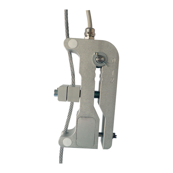
- Page 3 INSTALLATION OF HF 32/2/A LOAD CELL Fig. 1 Components of the load cell A- 2 m connecting cable F- Locking nut K-Tightening bracket. B- Flat washer. G- Tare screw. L-Rubber compression pad. C- Adjusting pin. H-Traction part. M-Wire rope. D- Locking ring.
- Page 4 INSTALLATION OF HF 32/2/A LOAD CELL Positioning the adjusting pin as a function of the effort in the wire rope For wire rope from 17 mm diameter and for loads ranging from 300 kg to 2300 kg. For wire rope from 18 mm to 22 mm diameter and for loads ranging from 350 kg to 5000 kg.
- Page 5 INSTALLATION OF HF 32/2/A LOAD CELL Correct positioning of the tightening bracket depending on the diameter of the wire rope. 17 mm wire rope without the rubber compression pad, M6 screws * 40mm (supplied) M6 screws * 40 mm (x2)
- Page 6 OPERATION AND ADJUSTMENT OF HF 32/2/A LOAD CELL Earth Brown) (Black) (Blue) Control Lifting voltage Alarm Contactor BROWN/BLUE = NC (Normally closed) BROWN/BLACK = NO (Normally open) Fig. 4 The switching power is 4A, 220 Vac (0.3A, 250 Vdc). ( It is therefore possible to connect in series in the upper limit switch circuit).
- Page 7 INSTALLATION OF HF 32 / . / A . TWO TRIP POINTS Components of the load cell A – Cable connection. B – Flat washer. C – Adjust pin. D – Locking ring E – Load cell body. F – Tare screw for trip point N° 1. G –...
- Page 8 NOTES : MS 32/2/A R 03/03...
Need help?
Do you have a question about the HF 32/2/A and is the answer not in the manual?
Questions and answers