Table of Contents
Advertisement
Quick Links
Oasis
READ AND SAVE THESE INSTRUCTIONS
®
USER
SCC P/N
MANUAL
21-90271
MICROMARKET SELF-SERVICE REFRIGERATED "BOX CASES"
> SELF-CONTAINED & REMOTE UNITS
> ELECTRONICALLY CONTROLLED ROLLING DOOR WITH BATTERY BACKUP
For Electronically
Controlled Door
Information, See
Page 7 In This
Manual.
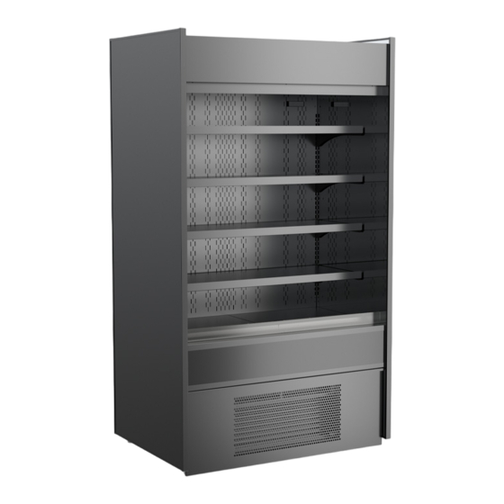
This Manual Reflects Oasis Model BV4732.
However, It May Also Be Applicable To
Model BV4732 Shown Above
Models Not Listed Herein.
Structural Concepts Corp. ∙ 888 E. Porter Rd ∙ Muskegon, MI 49441 Phone: 231.798.8888 Fax: 231.798.4960 ∙ www.structuralconcepts.com
REV E DATE: 09/07/2022
USER MANUALS\21-90271_OASIS_ USER MANUAL_BV4732_REF_SELF-SVC_ELEC-CNTR DOOR_BOX CASE
Advertisement
Table of Contents
Troubleshooting

Related Manuals for Structural Concepts Oasis BV4732


Summary of Contents for Structural Concepts Oasis BV4732
- Page 1 However, It May Also Be Applicable To Model BV4732 Shown Above Models Not Listed Herein. Structural Concepts Corp. ∙ 888 E. Porter Rd ∙ Muskegon, MI 49441 Phone: 231.798.8888 Fax: 231.798.4960 ∙ www.structuralconcepts.com REV E DATE: 09/07/2022 USER MANUALS\21-90271_OASIS_ USER MANUAL_BV4732_REF_SELF-SVC_ELEC-CNTR DOOR_BOX CASE...
-
Page 2: Table Of Contents
TABLE OF CONTENTS OVERVIEW / TYPE / COMPLIANCE / WARNINGS / PRECAUTIONS / WIRING / PLUGS .………….. INSTALLATION: CASE REMOVAL (VIA LEVELERS & CASTERS) ………….……………………….. INSTALLATION, CONTINUED: POSITIONING & ALIGNING CASE / ADJUSTING LEVELERS .….. INSTALLATION, CONTINUED: ELECTRONICALLY CONTROLLED DOOR / IMPORTANT! CONNECT BATTERY TO BATTERY BACKUP SYSTEM! …….......... -
Page 3: Overview / Type / Compliance / Warnings / Precautions / Wiring / Plugs - Page 1 Of 2
Type II display refrigerators are intended for use in an OVERVIEW area where environmental conditions are controlled and These Structural Concepts Oasis®nmerchandisers maintained so that the ambient temperature does not are designed to merchandise packaged products at exceed 80 °F (27 °C) and 60% maximum humidity. - Page 4 Each case has its own wiring diagram folded and in its This disclosure statement has been reviewed and own packet. approved by Structural Concepts and Structural Concepts attests, under penalty of perjury, that these statements are true and accurate. CAUTION! LAMP REPLACEMENT GUIDELINES...
-
Page 5: Installation: Case Removal (Via Levelers & Casters)
INSTALLATION: CASE REMOVAL (VIA LEVELERS & CASTERS) 1. Removing Case Shipping Brackets That Are Attached To Skid Remove screws holding Case Shipping Brackets to skid. Remove Case Shipping Brackets from Skid. See illustrations below. Note: Shipping Brackets will vary in size, shape, material and location depending upon case type and model. -
Page 6: Installation, Continued: Positioning & Aligning Case / Adjusting Levelers
INSTALLATION, CONTINUED: POSITIONING & ALIGNING CASE / ADJUSTING LEVELERS 3. Position & Align Alongside Other Cases Before adjusting levelers, make certain that the case is in proper position. This may require the repositioning of the case you are installing or the already positioned case(s). 4. -
Page 7: Connect Battery To Battery Backup System
INSTALLATION, CONTINUED: ELECTRONICALLY CONTROLLED DOOR / CONNECT BATTERY! 5. Front Grille Removal to press the red DOOR RESET button (which resets the thermostat alarm). Then, raise the door again by Front grille must be removed to access main using DOOR CONTROL switch. power switch, thermostat and door controls. -
Page 8: Front Grille Removal / Condenser Package / Overflow Pan / Main Power
FRONT GRILLE REMOVAL / CONDENSER PACKAGE / OVERFLOW PAN / MAIN POWER SWITCH 1. Removable Front Grille Refrigeration assembly base rests on plastic glides. Front grille can be removed/replaced via slot and Slide condenser package out from under case. hook method (shown below). -
Page 9: Evaporator Coil Fan Discharge / Txv (Thermostatic Expansion Valve)
ELECTRONICALLY CONTROLLED ROLLING DOOR Electronically Controlled Rolling Door Electronically controlled rolling door is NOT able to be raised or lowered by hand. Handles are from factory stock and are NOT able to be used for raising or lowering door. ... - Page 10 EVAPORATOR COIL FAN DISCHARGE / TXV (THERMOSTATIC EXPANSION VALVE) 1. Evaporator Coil Fan Discharge When main power switch is turned on, refrigeration assembly will energize (see FRONT GRILLE REMOVAL / CONDENSER PACKAGE / OVERFLOW PAN / MAIN POWER SWITCH section for start- -up specifics).
-
Page 11: Honeycomb Air Diffuser / Led Light Fixtures / Caster Locking Operation
Removal / Replacement of LED Light Fixtures Removal of lamp: LED lights rarely require change-out. Contact Structural Concepts’ Technical Service Department for replacement parts (see the Technical Service section of operating manual). Replacement of lamp: To replace LED Light Fixture, disconnect existing light from its brackets. -
Page 12: Wall Spacing / Rear Venting
WALL SPACING / REAR VENTING Wall Spacing / Rear Venting (May Not Be Applicable To Your Model) Caution: Venting is an integral part of case temperature management. Do not remove rear panel! Rear Grille: Rear grille may be removed (by removing 4 screws) for service or maintenance of condenser unit. -
Page 13: Self-Contained Hot Gas Loop Condensate Package Layouts - Page 1 Of 3
SELF-CONTAINED HOT GAS LOOP CONDENSATE PACKAGE LAYOUTS - PAGE 1 of 3 1. Self-Contained Hot Gas Loop Condensate Package Caution: Only trained service providers are to provide maintenance and service to unit. Warning! Disconnect power before providing maintenance and service to unit. ... - Page 14 SELF-CONTAINED HOT GAS LOOP CONDENSATE PACKAGE LAYOUTS - PAGE 2 of 3 2. Self-Contained Hot Gas Loop Condensate Package Caution: Only trained service providers are to provide maintenance and service to unit. Warning! Disconnect power before providing maintenance and service to unit. Condenser Coil Fan &...
- Page 15 SELF-CONTAINED HOT GAS LOOP CONDENSATE PACKAGE LAYOUTS - PAGE 3 of 3 3. Self-Contained Hot Gas Loop Condensate Package Caution: Only trained service providers are to provide maintenance and service to unit. Warning! Disconnect power before providing maintenance and service to unit. ...
-
Page 16: Load Level Guide / Temperature Guide
LOAD LEVEL GUIDE / TEMPERATURE GUIDE (MODEL B42 SHOWN / APPLICABLE TO OTHERS) LOAD LEVEL & TEMPERATURE GUIDE IMPROPER PRODUCT PLACEMENT PREVENTS PROP- CAUTION 1: TO PREVENT PRODUCT FROM FREEZING OR BECOMING ER AIRFLOW CAUSING PRODUCT TO FREEZE OR OVERLY WARM, ALLOW AT LEAST 1”... -
Page 17: Cleaning Schedule (To Be Performed By Store Personnel)
CLEANING SCHEDULE - TO BE PERFORMED BY STORE PERSONNEL FREQ. INSTRUCTIONS Daily Acrylic Air Deflectors: Clean with a warm water and mild soap solution and soft cloth. Never use ammonia-based cleaners (nor household or commercial window cleaner) on acrylic. Daily Shelves &... -
Page 18: Troubleshooting (To Be Performed By Trained Service Providers Only)
PREVENTIVE MAINTENANCE (QUARTERLY) - PERFORMED BY TRAINED SERVICE PROVIDER - 1 of 5 WARNING! TURN OFF CASE BEFORE PERFORMING PREVENTIVE MAINTENANCE! PREVENTIVE INSTRUCTIONS MAINTENANCE Case Interior Tub, Coil, Drain, Fan Blades, Motors, Brackets: Disconnect power from case before cleaning the tub, coil, fan, motor and drain area! ... - Page 19 PREVENTIVE MAINTENANCE (QUARTERLY) - PERFORMED BY TRAINED SERVICE PROVIDER - 2 of 5 WARNING! TURN OFF CASE BEFORE PERFORMING PREVENTIVE MAINTENANCE! PREVENTIVE INSTRUCTIONS MAINTENANCE Case Interior Under Case Cleaning: Whenever refrigeration assembly is removed from underside of case, vacuum (or broom) under case to remove all dust, debris and dirt that may collect.
- Page 20 Return wicking material to mounting brackets. If wicking material is tattered, torn or disintegrating, replace with new. If wicking material is not available, contact Structural Concepts. See toll-free number at last page of operating manual. Slide condenser package back under case.
- Page 21 PREVENTIVE MAINTENANCE (QUARTERLY) - PERFORMED BY TRAINED SERVICE PROVIDER - 4 of 5 PREVENTIVE INSTRUCTIONS MAINTENANCE Case Interior Honeycomb Air Diffuser: A. Wedge a non-metallic device of suitable strength (such as a ballpoint pen) between honeycomb and its housing. Caution! Use care not to dislodge the heating wire (that prevents condensation on the honeycomb retainer).
- Page 22 PREVENTIVE MAINTENANCE (ANNUALLY) - PERFORMED BY TRAINED SERVICE PROVIDER - 5 of 5 PREVENTIVE INSTRUCTIONS MAINTENANCE Case Interior Optional Clean Sweep® Condensing Coil Cleaner: Important! Disconnect power from case before cleaning the Clean Sweep® Condenser Coil Cleaner! Remove front grille (by removing 4 screws). ...
-
Page 23: Troubleshooting (To Be Performed By Trained Service Provider Only) - Page 1 Of 3
Slide condensate package out from under unit. After refrigeration system has been carefully slid out, replace wicking material with new. If wicking material is not available, contact Structural Concepts. See toll-free number at last page of this operating manual. ... - Page 24 TROUBLESHOOTING (TO BE PERFORMED BY TRAINED SERVICE PROVIDER ONLY) - PAGE 2 of 3 CONDITION TROUBLESHOOTING Fan Emits Excessive Check that the case is aligned, level and plumb. Noise Check evaporator fan for cleanliness. Unplug/power off fan motors. Check motor shaft for bearing wear. Check that fan motors are securely mounted in brackets.
- Page 25 TROUBLESHOOTING (TO BE PERFORMED BY TRAINED SERVICE PROVIDER ONLY) - PAGE 3 of 3 CONDITION TROUBLESHOOTING Case Lights Are Not Check that light switch is in the on position. Working Check that ALL of the light cords and plugs are properly connected. See MAINTENANCE - LIGHT FIXTURES (LED LIGHT FIXTURES) section.
-
Page 26: Troubleshooting (By Trained Service Providers Only) - Condensing System
TROUBLESHOOTING - CONDENSING SYSTEM (BY TRAINED SERVICE PROVIDERS ONLY) CONDITION TROUBLESHOOTING Head Pressure Too High Check that the condensing coil is not dirty or covered. Check that condensing fans are working. Check that refrigerant is not overcharged. Perform sub-cooling check and verify that no contaminates are in system. Check that liquid line filter dryer is not plugged. -
Page 27: Troubleshooting (By Trained Service Providers Only) - Evaporator System
TROUBLESHOOTING - EVAPORATOR SYSTEM (BY TRAINED SERVICE PROVIDERS ONLY) CONDITION TROUBLESHOOTING Low Suction Pressure Check if sight glass is flashing or showing low charge. Check that expansion valve (TXV) isn’t restricted. Check element charge. Check that liquid line or filter isn’t restricted. Check that refrigeration lines and/or hoses are not kinked on either high or low sides. -
Page 28: Serial Label Location & Information Listed / Tech Info & Service
TECHNICAL SERVICE page in this manual for Serial labels are affixed at a wide range of places instructions on contacting Structural Concepts’ (on the header, near thermostat, at case rear, Technical Service Department. behind panels/toe-kicks, on electrical boxes, etc.). -
Page 29: Carel® Controller Operating Instruction
CAREL® ir33 PLATFORM PROGRAMMABLE CONTROLLER FOR REFRIGERATED UNITS - PAGE 1 of 3 Integrated Electronic Microprocessor Controller Programming The Instrument ▲ To Modify Defrost, Differential and Other Parameters mute 1. Press & hold “Prg” & “SET” keys together for at least five (5) seconds; display mute will flash “0,”... - Page 30 CAREL® ir33 PLATFORM PROGRAMMABLE CONTROLLER FOR REFRIGERATED UNITS - PAGE 2 of 3 Integrated Electronic Microprocessor Controller User Interface - Display Summary Table of Alarm and Signals: Display, Buzzer and Relay This data derived from Carel® Controller Material: ir33 +030220441 - rel. 2.0 - 01.05.2006. User Manuals\Carel ir33 Platform Programmable Controller For Refrig Units - Rev C Date: 06/22/2022 reset alarms w/manual reset / reset HACCP alarms / reset temp.
- Page 31 CAREL® ir33 PLATFORM PROGRAMMABLE CONTROLLER FOR REFRIGERATED UNITS - PAGE 3 of 3 Integrated Electronic Microprocessor Controller Summary Table of Operating Parameters CODE PARAMETER UOM* TYPE MINIMUM MAXIMUM DEFAULT Select Celsius (°C) or Fahrenheit (°F) flag Calibration of probe 1 °C/°F Calibration of probe 2 °C/°F...
-
Page 32: Technical Service Contact Information & Warranty Information
LIMITED WARRANTY Overview: All sales by Structural Concepts Corporation (hereafter, “SCC”) are subject to the following limited warranty. “Goods” refers to the product or products being sold by SCC. Warranty Scope: Warranty is for equipment sold in the United States, Canada, Mexico and Puerto Rico. Equipment sold elsewhere may carry modified warranties.
Need help?
Do you have a question about the Oasis BV4732 and is the answer not in the manual?
Questions and answers